
Recommended
Recommended
More Related Content
Similar to Caterpillar Cat 941 941B TRACK LOADER (Prefix 80H) Service Repair Manual Instant Download (80H03884-05702).pdf
Similar to Caterpillar Cat 941 941B TRACK LOADER (Prefix 80H) Service Repair Manual Instant Download (80H03884-05702).pdf (20)
More from ti76cui
More from ti76cui (20)
Recently uploaded
Recently uploaded (20)
Caterpillar Cat 941 941B TRACK LOADER (Prefix 80H) Service Repair Manual Instant Download (80H03884-05702).pdf
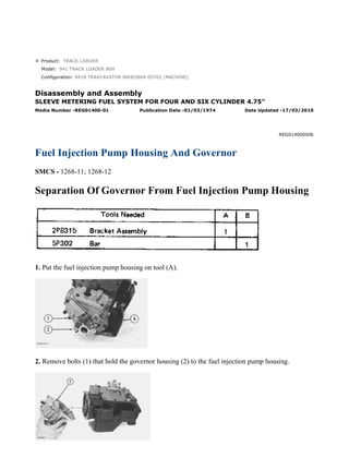
- 1. Product: TRACK LOADER Model: 941 TRACK LOADER 80H Configuration: 941B TRAXCAVATOR 80H03884-05702 (MACHINE) Disassembly and Assembly SLEEVE METERING FUEL SYSTEM FOR FOUR AND SIX CYLINDER 4.75" Media Number -REG01400-01 Publication Date -01/03/1974 Date Updated -17/03/2010 REG014000006 Fuel Injection Pump Housing And Governor SMCS - 1268-11; 1268-12 Separation Of Governor From Fuel Injection Pump Housing 1. Put the fuel injection pump housing on tool (A). 2. Remove bolts (1) that hold the governor housing (2) to the fuel injection pump housing. 1/6 941B TRAXCAVATOR 80H03884-05702 (MACHINE)(UEG0680S - 00) - Documen... 2022/1/17 https://127.0.0.1/sisweb/sisweb/techdoc/techdoc_print_page.jsp?returnurl=/sis...
- 2. 3. Remove governor housing (2) from pump housing. 4. Remove cover (5) over the torque spring. 5. Remove spring (8), (wave) washer (7) and guide (6) from governor housing. 6. Remove seat (3) and over fueling spring (4). 7. Pull shaft (9) up and remove shaft and lever from the housing. 8. Remove torque spring assembly (10) and pin. NOTE: Some fuel systems do not have a torque spring. They have only a stop. 9. Remove riser (follower) (11) from the shaft. 10. Remove ring and lever (12) from the dowel. 11. Remove cover (13) for the flyweights with tool (B). NOTE: Tool (B) can cause damage to the cover. Always inspect cover and install a new cover if needed. 2/6 941B TRAXCAVATOR 80H03884-05702 (MACHINE)(UEG0680S - 00) - Documen... 2022/1/17 https://127.0.0.1/sisweb/sisweb/techdoc/techdoc_print_page.jsp?returnurl=/sis...
- 3. 12. Install timing pin (14) to hold the camshaft from turning. 13. Remove bolts (15) that hold flyweight assembly to camshaft. 14. Remove the flyweight assembly (16) from the fuel injection pump housing. 15. Remove the timing pin from the housing. Connection Of Governor To Fuel Injection Pump Housing 1. Put the fuel injection pump housing on tool (A). 2. Install timing pin (1) to keep the camshaft from turning. 3. Put flyweight assembly (2) in position on the camshaft. 3/6 941B TRAXCAVATOR 80H03884-05702 (MACHINE)(UEG0680S - 00) - Documen... 2022/1/17 https://127.0.0.1/sisweb/sisweb/techdoc/techdoc_print_page.jsp?returnurl=/sis...
- 4. NOTICE Be sure pin (3) that holds shaft is in the correct position on back of the flyweight assembly. 4. Install new bolts for the flyweight assembly. NOTE: The bolts for the flyweight assembly have a locking material on the threads and must not be used more than one time. 5. Install cover over the flyweight assembly with tool (B). 6. Grind a taper on the bottom edge of a 1/8" screwdriver (4). Install the screwdriver through the bolt hole in the governor housing. The screwdriver must fit evenly against the flyweight assembly cover. Make a mark (stake) in four places around the cover in line with the groove in the camshaft. NOTICE Never install a used flyweight cover that is bent. 4/6 941B TRAXCAVATOR 80H03884-05702 (MACHINE)(UEG0680S - 00) - Documen... 2022/1/17 https://127.0.0.1/sisweb/sisweb/techdoc/techdoc_print_page.jsp?returnurl=/sis...
- 5. 7. Install lever (5) on the dowel. Install ring (6) that holds lever on dowel. 8. Install pin (7) in the housing with the round end down. 9. Put riser (follower) (10) in position between the flyweights. Lift the flyweight up with a piece of wire and push riser (follower) forward. 10. Put lever (9) into position in groove of riser (follower) (10) and ball end engaged in the sleeve shaft lever (8). Install shaft to hold lever in place. NOTICE If lever (9) is not installed correctly, the governor cannot operate and can cause the engine to over speed. 5/6 941B TRAXCAVATOR 80H03884-05702 (MACHINE)(UEG0680S - 00) - Documen... 2022/1/17 https://127.0.0.1/sisweb/sisweb/techdoc/techdoc_print_page.jsp?returnurl=/sis...
- 6. 11. Install over fueling spring (13) and seat (12) on shaft. 12. Install stud (14) and torque spring or stop bar (11) on the housing. NOTICE The screw that holds the torque spring must not go beyond the inner surface of the governor housing. 13. Install cover (15) over torque spring after adjustment has been made. 14. Install guide, (wave) washer and spring (16) in the governor housing. 15. Put the governor housing on the fuel injection pump housing and install the bolts. end by: a) make adjustment of fuel system setting (See Fuel System Setting in Testing and Adjusting) 6/6 941B TRAXCAVATOR 80H03884-05702 (MACHINE)(UEG0680S - 00) - Documen... 2022/1/17 https://127.0.0.1/sisweb/sisweb/techdoc/techdoc_print_page.jsp?returnurl=/sis...
- 7. Product: TRACK LOADER Model: 941 TRACK LOADER 80H Configuration: 941B TRAXCAVATOR 80H03884-05702 (MACHINE) Disassembly and Assembly SLEEVE METERING FUEL SYSTEM FOR FOUR AND SIX CYLINDER 4.75" Media Number -REG01400-01 Publication Date -01/03/1974 Date Updated -17/03/2010 REG014000007 Governor SMCS - 1264-15; 1264-16 Disassemble Governor start by: a) separation of governor from fuel injection pump housing 1. Remove shaft (2). Remove pin (1) from shaft. 2. Remove pins (3) from the flyweights. Remove flyweights (4). 3. Remove ring, races (6) and bearing from the riser (follower) (5). 1/6 941B TRAXCAVATOR 80H03884-05702 (MACHINE)(UEG0680S - 00) - Documen... 2022/1/17 https://127.0.0.1/sisweb/sisweb/techdoc/techdoc_print_page.jsp?returnurl=/sis...
- 8. 4. Remove cover (7) and spring (8) from governor housing. NOTE: There is force on the cover from the spring. 5. Remove seal (9) from cover. 6. Remove cover (10) for the low and high idle adjustment. 7. Remove locknut and screw (13) for the high idle adjustment. 8. Remove bolt (15) and washers for the low idle adjustment. 9. Remove spring (16) and guide. 10. Remove pin (14) and plate (11). 11. Remove shaft (12) from the housing. 12. Remove pin (18) and two spacers (17) from shaft. NOTE: Earlier fuel systems have a ball in place of spacers (17) and pin (18). 2/6 941B TRAXCAVATOR 80H03884-05702 (MACHINE)(UEG0680S - 00) - Documen... 2022/1/17 https://127.0.0.1/sisweb/sisweb/techdoc/techdoc_print_page.jsp?returnurl=/sis...
- 9. 13. Remove shaft (19) from the governor housing. 14. Remove washer (20) and levers (21) and (22) from governor housing. 15. Remove cover (23) from governor housing. 16. Remove seal (25) and bearing. 17. Remove seals (24) and (26) from governor housing. Assemble Governor 3/6 941B TRAXCAVATOR 80H03884-05702 (MACHINE)(UEG0680S - 00) - Documen... 2022/1/17 https://127.0.0.1/sisweb/sisweb/techdoc/techdoc_print_page.jsp?returnurl=/sis...
- 10. 1. Install bearing and seal in the housing with tool (A). The lip of the seal must be toward the bearing. 2. Install seal (1) in housing with tool (A). The lip of seal must be toward inside of housing. 3. Install seal (2) in housing with tooling (B). The lip of seal must be toward the inside of housing. 4. Install shaft (3) in the housing. 5. Install plates (4), spacers (8) and pin (7) on shaft. 6. Install shaft (5) in housing and through washer (9) and levers (6). 7. Install pin (11) in holes of the plates. 8. Install screw (10) and locknut for high idle adjustment. 4/6 941B TRAXCAVATOR 80H03884-05702 (MACHINE)(UEG0680S - 00) - Documen... 2022/1/17 https://127.0.0.1/sisweb/sisweb/techdoc/techdoc_print_page.jsp?returnurl=/sis...
- 11. 9. Install spring (13) and guide. 10. Install bolts (12) and washer for low idle adjustment. 11. Push plate and pin (11) over toward the bolt (12) and tighten the bolt. 12. Install seal in cover with tooling (B). The lip of seal must be toward the inside. 13. Install spring (15) in the cover. Install cover (14) on housing. NOTICE The spring (15) must be installed with the end of spring as shown. 14. Install cover (16) for the idle adjustment screws. 5/6 941B TRAXCAVATOR 80H03884-05702 (MACHINE)(UEG0680S - 00) - Documen... 2022/1/17 https://127.0.0.1/sisweb/sisweb/techdoc/techdoc_print_page.jsp?returnurl=/sis...
- 12. 15. Install bearing (19) between the races (18) on riser (follower) (17). Install ring (20) that holds the washers on the riser (follower). 16. Install pin in shaft (23). 17. Install flyweights (22) and pin (21). 18. Install shaft (23) in the flyweight assembly. end by: a) connection of governor to fuel injection pump housing 6/6 941B TRAXCAVATOR 80H03884-05702 (MACHINE)(UEG0680S - 00) - Documen... 2022/1/17 https://127.0.0.1/sisweb/sisweb/techdoc/techdoc_print_page.jsp?returnurl=/sis...
- 13. Product: TRACK LOADER Model: 941 TRACK LOADER 80H Configuration: 941B TRAXCAVATOR 80H03884-05702 (MACHINE) Disassembly and Assembly SLEEVE METERING FUEL SYSTEM FOR FOUR AND SIX CYLINDER 4.75" Media Number -REG01400-01 Publication Date -01/03/1974 Date Updated -17/03/2010 REG014000008 Fuel Check Valve And Bypass Valve SMCS - 1264-15; 1264-16 Remove Fuel Check Valve And Bypass Valve 1. Remove fuel from the pump housing and install on tool (A). 2. Remove cover (2) from top cover. 3. Remove fuel inlet and return housing (1) from top cover. 1/4 941B TRAXCAVATOR 80H03884-05702 (MACHINE)(UEG0680S - 00) - Documen... 2022/1/17 https://127.0.0.1/sisweb/sisweb/techdoc/techdoc_print_page.jsp?returnurl=/sis...
- 14. 4. Remove elbow (3) and disc (4) from fuel inlet and return housing. NOTE: The function of the disc (4) is to keep the fuel in the pump housing from returning to the tank when the engine is not in operation. If the fuel tank is higher than the fuel pump housing, disc and housing is not needed. 5. Remove cover (5) and fuel channel from pump housing. 6. Remove spring and bypass valve (6) from housing. 7. Remove check valve (7). 8. Remove fuel channel (8) and check valve from cover. 9. Remove check valve (9) and spring from fuel channel. NOTE: Earlier fuel systems have two check valves (7) and (9). Check valve (9) is not needed. Remove check valve (9) and fill the hole in fuel channel with weld or replace channel. Install Fuel Check Valve And Bypass Valve 1. Install fuel channel (1) on cover (2). 2/4 941B TRAXCAVATOR 80H03884-05702 (MACHINE)(UEG0680S - 00) - Documen... 2022/1/17 https://127.0.0.1/sisweb/sisweb/techdoc/techdoc_print_page.jsp?returnurl=/sis...
- 15. 2. Install spring and bypass valve (4) in housing with the rounded end up. 3. Install check valve (3) evenly in pump housing. NOTE: Do not install a check valve that is bent. 4. Install cover on pump housing. Be sure the bypass valve spring is in the groove in the cover. 5. Install disc (5) and elbow on fuel inlet and return housing. 6. Install fuel inlet and return housing (6) on cover (8). 7. Install cover (7) on cover (8). 8. Remove fuel injection pump housing and governor from tool (A). 3/4 941B TRAXCAVATOR 80H03884-05702 (MACHINE)(UEG0680S - 00) - Documen... 2022/1/17 https://127.0.0.1/sisweb/sisweb/techdoc/techdoc_print_page.jsp?returnurl=/sis...
- 16. Product: TRACK LOADER Model: 941 TRACK LOADER 80H Configuration: 941B TRAXCAVATOR 80H03884-05702 (MACHINE) Disassembly and Assembly SLEEVE METERING FUEL SYSTEM FOR FOUR AND SIX CYLINDER 4.75" Media Number -REG01400-01 Publication Date -01/03/1974 Date Updated -17/03/2010 REG014000009 Fuel Injection Pumps SMCS - 1251-12; 1251-15; 1251-16; 1251-11 Fuel Injection Pump And Housing 1/6 941B TRAXCAVATOR 80H03884-05702 (MACHINE)(UEG0680S - 00) - Documen... 2022/1/17 https://127.0.0.1/sisweb/sisweb/techdoc/techdoc_print_page.jsp?returnurl=/sis...
- 17. 2/6 941B TRAXCAVATOR 80H03884-05702 (MACHINE)(UEG0680S - 00) - Documen... 2022/1/17 https://127.0.0.1/sisweb/sisweb/techdoc/techdoc_print_page.jsp?returnurl=/sis...
- 18. Remove Fuel Injection Pumps NOTICE Before any service work is to be done on the fuel system the outer surface of injection pump housing must be clean. 1. Remove the cover assembly (1) from the pump housing. Remove spring for the bypass valve. 3/6 941B TRAXCAVATOR 80H03884-05702 (MACHINE)(UEG0680S - 00) - Documen... 2022/1/17 https://127.0.0.1/sisweb/sisweb/techdoc/techdoc_print_page.jsp?returnurl=/sis...
- 19. 2. Loosen the bushing (2) from the pump housing with tool (A). NOTE: Do not loosen the screws (3) that hold levers to shaft when removing or installing pumps. If levers are moved, fuel pump adjustment will be changed. 3. Remove the fuel injection pump from the pump housing. The sleeve on the plunger will slide off the lever as the pump is removed. Install Fuel Injection Pumps 1. Put the fuel injection pump (1) in the bore of pump housing. 2. The sleeve (2) will be engaged with lever when installed correctly. NOTICE If levers have been moved on the shaft, fuel pump adjustment must be made. (See TESTING AND ADJUSTING). 3. Tighten the bushing with wrench (A) to a torque of 70 ± 5 lb.ft. (9.7 ± 0.7 mkg). 4/6 941B TRAXCAVATOR 80H03884-05702 (MACHINE)(UEG0680S - 00) - Documen... 2022/1/17 https://127.0.0.1/sisweb/sisweb/techdoc/techdoc_print_page.jsp?returnurl=/sis...
- 20. 4. Put the spring on the bypass valve. Install the cover assembly on the pump housing. Be sure the spring (4) is in position in the cover. Disassemble Fuel Injection Pumps start by: a) remove fuel injection pumps 1. Remove the bushing (1) from the bonnet (2). 2. Remove the ring (3) from the bonnet and barrel (7). Remove the check valve (6) and spring (4) from the bonnet. 3. Remove the spring (8) and washer (5). Remove the plunger (9) and sleeve (10). NOTE: Keep the plunger and sleeve with their respective barrel for installation. Do not use plungers, sleeves, and barrels with other plungers, sleeves, and barrels. Assemble Fuel Injection Pumps 5/6 941B TRAXCAVATOR 80H03884-05702 (MACHINE)(UEG0680S - 00) - Documen... 2022/1/17 https://127.0.0.1/sisweb/sisweb/techdoc/techdoc_print_page.jsp?returnurl=/sis...
- 21. 1. Install the sleeve (4), plunger (5), spring (2), and washer (3) on the barrel (1). NOTE: Be sure sleeve and plunger are installed in original barrel, and large hole in plunger is up. 2. Install check valve and spring in bonnet. Connect the barrel and bonnet and install the ring. Install the bushing on the bonnet. end by: a) install fuel injection pumps 6/6 941B TRAXCAVATOR 80H03884-05702 (MACHINE)(UEG0680S - 00) - Documen... 2022/1/17 https://127.0.0.1/sisweb/sisweb/techdoc/techdoc_print_page.jsp?returnurl=/sis...
- 22. Product: TRACK LOADER Model: 941 TRACK LOADER 80H Configuration: 941B TRAXCAVATOR 80H03884-05702 (MACHINE) Disassembly and Assembly SLEEVE METERING FUEL SYSTEM FOR FOUR AND SIX CYLINDER 4.75" Media Number -REG01400-01 Publication Date -01/03/1974 Date Updated -17/03/2010 REG014000010 Fuel Transfer Pump SMCS - 1156-11; 1256-12 Remove Fuel Transfer Pump 1/7 941B TRAXCAVATOR 80H03884-05702 (MACHINE)(UEG0680S - 00) - Documen... 2022/1/17 https://127.0.0.1/sisweb/sisweb/techdoc/techdoc_print_page.jsp?returnurl=/sis...
- 23. Suggest: For more complete manuals. Please go to the home page. https://www.ebooklibonline.com If the above button click is invalid. Please download this document first, and then click the above link to download the complete manual. Thank you so much for reading
- 24. 2/7 941B TRAXCAVATOR 80H03884-05702 (MACHINE)(UEG0680S - 00) - Documen... 2022/1/17 https://127.0.0.1/sisweb/sisweb/techdoc/techdoc_print_page.jsp?returnurl=/sis...
- 25. 1. Install the fuel injection pump housing on tool (A). 2. Install timing pin (1) to keep the injection pump camshaft from turning during disassembly and assembly. 3. Install bolt (B) in the threads of sleeve (3). Tighten the bolt until sleeve can be removed. NOTICE Do not hit on bolt or sleeve. This will cause damage to the unit. 4. Remove bolts (4) that hold body to the housing. 5. Remove body (2) from the housing. 6. Remove idler gear (6) from body. 7. Remove O-ring seal (5) and the two lip-type seals from body. 3/7 941B TRAXCAVATOR 80H03884-05702 (MACHINE)(UEG0680S - 00) - Documen... 2022/1/17 https://127.0.0.1/sisweb/sisweb/techdoc/techdoc_print_page.jsp?returnurl=/sis...