
Recommended
Recommended
More Related Content
Similar to Caterpillar Cat 977K 977L TRACK LOADER (Prefix 48J) Service Repair Manual Instant Download (48J01059-02010).pdf
Similar to Caterpillar Cat 977K 977L TRACK LOADER (Prefix 48J) Service Repair Manual Instant Download (48J01059-02010).pdf (20)
More from gua6982552kun
More from gua6982552kun (20)
Recently uploaded
Recently uploaded (20)
Caterpillar Cat 977K 977L TRACK LOADER (Prefix 48J) Service Repair Manual Instant Download (48J01059-02010).pdf
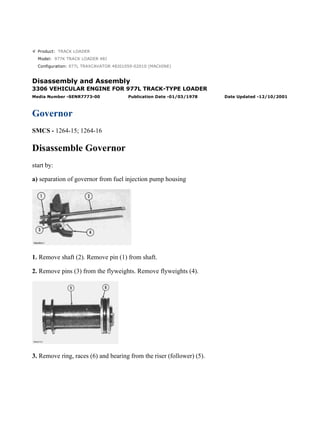
- 1. Product: TRACK LOADER Model: 977K TRACK LOADER 48J Configuration: 977L TRAXCAVATOR 48J01059-02010 (MACHINE) Disassembly and Assembly 3306 VEHICULAR ENGINE FOR 977L TRACK-TYPE LOADER Media Number -SENR7773-00 Publication Date -01/03/1978 Date Updated -12/10/2001 Governor SMCS - 1264-15; 1264-16 Disassemble Governor start by: a) separation of governor from fuel injection pump housing 1. Remove shaft (2). Remove pin (1) from shaft. 2. Remove pins (3) from the flyweights. Remove flyweights (4). 3. Remove ring, races (6) and bearing from the riser (follower) (5). 1/6 977L TRAXCAVATOR 48J01059-02010 (MACHINE)(UEH0794S - 00) - Document... 2021/10/19 https://127.0.0.1/sisweb/sisweb/techdoc/techdoc_print_page.jsp?returnurl=/sis...
- 2. 4. Remove cover (7) and spring (8) from governor housing. NOTE: There is force on the cover from the spring. 5. Remove seal (9) from cover. 6. Remove cover (10) for the low and high idle adjustment. 7. Remove locknut and screw (13) for the high idle adjustment. 8. Remove bolt (15) and washers for the low idle adjustment. 9. Remove spring (16) and guide. 10. Remove pin (14) and plate (11). 11. Remove shaft (12) from the housing. 12. Remove pin (18) and two spacers (17) from shaft. NOTE: Earlier fuel systems have a ball in place of spacers (17) and pin (18). 2/6 977L TRAXCAVATOR 48J01059-02010 (MACHINE)(UEH0794S - 00) - Document... 2021/10/19 https://127.0.0.1/sisweb/sisweb/techdoc/techdoc_print_page.jsp?returnurl=/sis...
- 3. 13. Remove shaft (19) from the governor housing. 14. Remove washer (20) and levers (21) and (22) from governor housing. 15. Remove cover (23) from governor housing. 16. Remove seal (25) and bearing. 17. Remove seals (24) and (26) from governor housing. Assemble Governor 3/6 977L TRAXCAVATOR 48J01059-02010 (MACHINE)(UEH0794S - 00) - Document... 2021/10/19 https://127.0.0.1/sisweb/sisweb/techdoc/techdoc_print_page.jsp?returnurl=/sis...
- 4. 1. Install bearing and seal in the housing with tool (A). The lip of the seal must be toward the bearing. 2. Install seal (1) in housing with tool (A). The lip of seal must be toward inside of housing. 3. Install seal (2) in housing with tooling (B). The lip of seal must be toward the inside of housing. 4. Install shaft (3) in the housing. 5. Install plates (4), spacers (8) and pin (7) on shaft. 6. Install shaft (5) in housing and through washer (9) and levers (6). 7. Install pin (11) in holes of the plates. 4/6 977L TRAXCAVATOR 48J01059-02010 (MACHINE)(UEH0794S - 00) - Document... 2021/10/19 https://127.0.0.1/sisweb/sisweb/techdoc/techdoc_print_page.jsp?returnurl=/sis...
- 5. 8. Install screw (10) and locknut for high idle adjustment. 9. Install spring (13) and guide. 10. Install bolts (12) and washer for low idle adjustment. NOTICE After the fuel injection pump housing and governor have been installed on the engine, make an adjustment for the high and low idle. See GOVERNOR ADJUSTMENT as shown in TESTING AND ADJUSTING. 11. Push plate and pin (11) over toward the bolt (12) and tighten the bolt. 12. Install seal in cover with tooling (B). The lip of seal must be toward the inside. 13. Install spring (15) in the cover. Install cover (14) on housing. NOTICE 5/6 977L TRAXCAVATOR 48J01059-02010 (MACHINE)(UEH0794S - 00) - Document... 2021/10/19 https://127.0.0.1/sisweb/sisweb/techdoc/techdoc_print_page.jsp?returnurl=/sis...
- 6. The spring (15) must be installed with the end of spring as shown. 14. Install cover (16) for the idle adjustment screws. 15. Install bearing (19) between the races (18) on riser (follower) (17). Install ring (20) that holds the washers on the riser (follower). 16. Install pin in shaft (23). 17. Install flyweights (22) and pin (21). 18. Install shaft (23) in the flyweight assembly. end by: a) connection of governor to fuel injection pump housing. 6/6 977L TRAXCAVATOR 48J01059-02010 (MACHINE)(UEH0794S - 00) - Document... 2021/10/19 https://127.0.0.1/sisweb/sisweb/techdoc/techdoc_print_page.jsp?returnurl=/sis...
- 7. Product: TRACK LOADER Model: 977K TRACK LOADER 48J Configuration: 977L TRAXCAVATOR 48J01059-02010 (MACHINE) Disassembly and Assembly 3306 VEHICULAR ENGINE FOR 977L TRACK-TYPE LOADER Media Number -SENR7773-00 Publication Date -01/03/1978 Date Updated -12/10/2001 Fuel Transfer Pump SMCS - 1256-11; 1256-12 Remove Fuel Transfer Pump start by: a) remove fuel injection pump housing and governor 1. Install the fuel injection pump housing on tool (A). NOTE: The fuel filter does not have to be removed to remove the fuel transfer pump. 2. Install timing pin (1) to keep the injection pump camshaft from turning during disassembly and assembly. 1/5 977L TRAXCAVATOR 48J01059-02010 (MACHINE)(UEH0794S - 00) - Document... 2021/10/19 https://127.0.0.1/sisweb/sisweb/techdoc/techdoc_print_page.jsp?returnurl=/sis...
- 8. 3. Install bolt (B) in the threads of sleeve (3). Tighten the bolt until the sleeve can be removed. NOTICE Do not hit on the bolt or sleeve. This will cause damage to the unit. 4. Remove four bolts (4) that hold the pump body to the housing. 5. Remove body (2) from the housing. 6. Remove idler gear (6) from the pump body. 7. Remove O-ring seal (5) and the two lip-type seals from the body. 8. Remove drive gear (8) from the shaft. 9. Remove key (7) from the shaft. Install Fuel Transfer Pump 2/5 977L TRAXCAVATOR 48J01059-02010 (MACHINE)(UEH0794S - 00) - Document... 2021/10/19 https://127.0.0.1/sisweb/sisweb/techdoc/techdoc_print_page.jsp?returnurl=/sis...
- 9. 1. Install the inner seal in the body with tool (A). The lip of the seal must be toward the pump gears. 2. Install the outer seal in the body with tool (B). The lip of the seal must be toward the outside. NOTICE Always be careful not to scratch or cause damage to the machined surface of the pump body. 3. Install O-ring seal (2) and idler gear (1) on the body. 3/5 977L TRAXCAVATOR 48J01059-02010 (MACHINE)(UEH0794S - 00) - Document... 2021/10/19 https://127.0.0.1/sisweb/sisweb/techdoc/techdoc_print_page.jsp?returnurl=/sis...
- 10. 4. Install the key and drive gear (3) on the shaft. 5. Install body (4) on the housing. 6. Install the bolts that hold the body to the housing. 7. Put sleeve (5) in position on the camshaft. NOTE: Timing pin (6) must be in position as shown to keep the camshaft from turning during assembly. 8. Install the sleeve on the camshaft with tool (C). NOTICE 4/5 977L TRAXCAVATOR 48J01059-02010 (MACHINE)(UEH0794S - 00) - Document... 2021/10/19 https://127.0.0.1/sisweb/sisweb/techdoc/techdoc_print_page.jsp?returnurl=/sis...
- 11. Do not hit the sleeve with a hammer to install it. This will put end force on the camshaft and cause damage to the other components in the pump housing. 9. The end clearance of the camshaft must be .023 ± .018 in. (0.58 ± 0.46 mm) after sleeve (5) is installed. end by: a) install fuel injection pump housing and governor. 5/5 977L TRAXCAVATOR 48J01059-02010 (MACHINE)(UEH0794S - 00) - Document... 2021/10/19 https://127.0.0.1/sisweb/sisweb/techdoc/techdoc_print_page.jsp?returnurl=/sis...
- 12. Product: TRACK LOADER Model: 977K TRACK LOADER 48J Configuration: 977L TRAXCAVATOR 48J01059-02010 (MACHINE) Disassembly and Assembly 3306 VEHICULAR ENGINE FOR 977L TRACK-TYPE LOADER Media Number -SENR7773-00 Publication Date -01/03/1978 Date Updated -12/10/2001 Fuel Check Valve And Bypass Valve SMCS - 1256-11; 1256-12 Remove Fuel Check Valve And Bypass Valve NOTICE Clean the outer surface of the fuel injection pump housing and governor before removal of the fuel check valve and bypass valve. 1. Remove fuel filter base (1). Remove the bolts that hold cover (2) in position. Remove the cover. 1/3 977L TRAXCAVATOR 48J01059-02010 (MACHINE)(UEH0794S - 00) - Document... 2021/10/19 https://127.0.0.1/sisweb/sisweb/techdoc/techdoc_print_page.jsp?returnurl=/sis...
- 13. 2. Remove check valve (3). 3. Remove spring (4) and the bypass valve. Install Fuel Check Valve And Bypass Valve 1. Install check valve (1) in the fuel injection pump housing. Make sure the check valve is installed evenly in the fuel injection pump housing. NOTE: Do not install a check valve that is bent. 2. Install bypass valve (3) and spring (2) in the fuel injection pump housing. 3. Put the cover in position on the fuel injection pump housing. Make sure the spring on the bypass valve is in the cover. Install the nine bolts that hold the cover in position. 4. Install the fuel filter base. 2/3 977L TRAXCAVATOR 48J01059-02010 (MACHINE)(UEH0794S - 00) - Document... 2021/10/19 https://127.0.0.1/sisweb/sisweb/techdoc/techdoc_print_page.jsp?returnurl=/sis...
- 14. Product: TRACK LOADER Model: 977K TRACK LOADER 48J Configuration: 977L TRAXCAVATOR 48J01059-02010 (MACHINE) Disassembly and Assembly 3306 VEHICULAR ENGINE FOR 977L TRACK-TYPE LOADER Media Number -SENR7773-00 Publication Date -01/03/1978 Date Updated -12/10/2001 Fuel Injection Pumps SMCS - 1251-12; 1251-15; 1251-16; 1251-11 Remove Fuel Injection Pumps NOTICE Before any service work is to be done on the fuel system the outer surface of the injection pump housing must be clean. 1. Remove cover assembly (1) from the pump housing. Remove the spring for the bypass valve. 1/4 977L TRAXCAVATOR 48J01059-02010 (MACHINE)(UEH0794S - 00) - Document... 2021/10/19 https://127.0.0.1/sisweb/sisweb/techdoc/techdoc_print_page.jsp?returnurl=/sis...
- 15. 2. Loosen bushing (2) from the pump housing with tool (A). NOTE: Do not loosen screws (3) when the pumps are removed or installed. If the levers are moved, the fuel pump adjustment will be changed. 3. Remove the fuel injection pump from the pump housing. The sleeve on the plunger will slide off the lever as the pump is removed. Install Fuel Injection Pumps 1. Put fuel injection pump (1) in the bore of the pump housing. 2. Sleeve (2) must be engaged with lever (3) when installed correctly. NOTICE If the levers (3) have been moved on the shaft, fuel pump adjustment must be made. See TESTING AND ADJUSTING. 3. Tighten the bushing with tool (A) to a torque of 70 ± 5 lb.ft. (95 ± 7 N·m). 4. Put the spring and bypass valve in place. Install the cover assembly on the pump housing. Be sure spring (4) is in position in the cover. 2/4 977L TRAXCAVATOR 48J01059-02010 (MACHINE)(UEH0794S - 00) - Document... 2021/10/19 https://127.0.0.1/sisweb/sisweb/techdoc/techdoc_print_page.jsp?returnurl=/sis...
- 16. Disassemble Fuel Injection Pumps start by: a) remove fuel injection pumps 1. Remove bushing (1) and seal (7) from bonnet (2). 2. Remove ring (4) from the bonnet and barrel (9). Remove check valve (3) and spring (8) from the bonnet. 3. Remove spring (10) and washer (5). Remove plunger (11) and sleeve (6). NOTE: Keep the plunger and sleeve with their respective barrel for installation. Do not use plungers, sleeves or barrels with other plungers, sleeves or barrels. Assemble Fuel Injection Pumps 3/4 977L TRAXCAVATOR 48J01059-02010 (MACHINE)(UEH0794S - 00) - Document... 2021/10/19 https://127.0.0.1/sisweb/sisweb/techdoc/techdoc_print_page.jsp?returnurl=/sis...
- 17. 1. Install sleeve (4), plunger (5), spring (2) and washer (3) on barrel (1). NOTICE Make sure the sleeve is installed with the thin edge up. NOTE: Be sure the sleeve and plunger are installed in their original barrel. Make sure the large hole in the plunger is up. 2. Install the check valve and spring in the bonnet. Connect the barrel and bonnet and install the ring. Install the seal and bushing on the bonnet. end by: a) install fuel injection pumps 4/4 977L TRAXCAVATOR 48J01059-02010 (MACHINE)(UEH0794S - 00) - Document... 2021/10/19 https://127.0.0.1/sisweb/sisweb/techdoc/techdoc_print_page.jsp?returnurl=/sis...
- 18. Product: TRACK LOADER Model: 977K TRACK LOADER 48J Configuration: 977L TRAXCAVATOR 48J01059-02010 (MACHINE) Disassembly and Assembly 3306 VEHICULAR ENGINE FOR 977L TRACK-TYPE LOADER Media Number -SENR7773-00 Publication Date -01/03/1978 Date Updated -12/10/2001 Hood, Muffler And Precleaner Assembly SMCS - 1055-12; 1055-11; 1062; 7251 Remove Hood, Muffler And Precleaner Assembly 1. Remove the right side guard (3). Remove the left side guard. 2. Loosen the clamp on muffler (2) under the hood. Remove muffler (2). 3. Remove precleaner (1). 4. Fasten a hoist to hood (4). Remove twelve bolts and washers and remove hood (4). Weight of the hood is 140 lb. (63 kg). Install Hood, Muffler And Precleaner Assembly 1/2 977L TRAXCAVATOR 48J01059-02010 (MACHINE)(UEH0794S - 00) - Document... 2021/10/19 https://127.0.0.1/sisweb/sisweb/techdoc/techdoc_print_page.jsp?returnurl=/sis...
- 19. 1. Fasten a hoist to hood (1) and put it in position on the machine. Install the twelve bolts and washers that hold the hood in place. 2. Put the muffler (2) in position and tighten the clamp that holds it. 3. Install precleaner (3). 4. Install the right side guard (4) and the left side guard. 2/2 977L TRAXCAVATOR 48J01059-02010 (MACHINE)(UEH0794S - 00) - Document... 2021/10/19 https://127.0.0.1/sisweb/sisweb/techdoc/techdoc_print_page.jsp?returnurl=/sis...
- 20. Suggest: For more complete manuals. Please go to the home page. https://www.ebooklibonline.com If the above button click is invalid. Please download this document first, and then click the above link to download the complete manual. Thank you so much for reading
- 21. Product: TRACK LOADER Model: 977K TRACK LOADER 48J Configuration: 977L TRAXCAVATOR 48J01059-02010 (MACHINE) Disassembly and Assembly 3306 VEHICULAR ENGINE FOR 977L TRACK-TYPE LOADER Media Number -SENR7773-00 Publication Date -01/03/1978 Date Updated -12/10/2001 Alternator SMCS - 1405-12; 1405-11 Remove Alternator NOTE: The radiator guard is removed from the machine for better photo illustration for the removal of the alternator. 1. Remove the two right side engine guards. 2. Put identification on wires (3) and disconnect the wires from the alternator. 3. Loosen bolt (1) and bolt (4) to release the tension on the vee belts (2). Remove the vee belts from the pulley on the alternator. 4. Remove bolt (1) and bolt (4) and remove the alternator (5). 5. Remove the nut that holds the pulley (6) to the alternator. Remove the pulley. 1/2 977L TRAXCAVATOR 48J01059-02010 (MACHINE)(UEH0794S - 00) - Document... 2021/10/19 https://127.0.0.1/sisweb/sisweb/techdoc/techdoc_print_page.jsp?returnurl=/sis...
- 22. Install Alternator 1. Put pulley (1) in position on the alternator. Install the nut that holds it. Tighten the nut to a torque of 75 ± 5 lb.ft. (100 ± 7 N·m). 2. Put alternator (5) in position on the bracket. Install bolt (2) and bolt (3) to hold it. Put the vee belts (4) in position on the pulley. 3. Connect the wires (6) to the alternator. Make sure the wires are in correct positions. 4. Install the two right side engine guards. 5. Make an adjustment to the tension on the vee belts. See FAN AND ALTERNATOR BELTS in LUBRICATION AND MAINTENANCE GUIDE. 2/2 977L TRAXCAVATOR 48J01059-02010 (MACHINE)(UEH0794S - 00) - Document... 2021/10/19 https://127.0.0.1/sisweb/sisweb/techdoc/techdoc_print_page.jsp?returnurl=/sis...