electrical load calculation, solar plant fault detection techniques, diesel generator set study, study of 11KV pole mounted substation,
study of underground cables,
electrical control room,
electricity bill calculation for residential consumer, Thumper test to detect fault location of underground cables.
1. 1
Sanjivani Rural Education Society’s
Sanjivani College of Engineering, Kopargaon-423 603
(An Autonomous Institute, Affiliated to Savitribai Phule Pune University, Pune)
NAAC ‘A’ Grade Accredited
Name Wattage
Ceiling fan 75W
Projector 296W-300W
Computer 240W-300W
Printer 340W-350W
Exhaust Fan 40W-50W
Tubelight 20W
LED Porch Light 15W
Photo Copier Machine 800W-1.5KW
Name Wattage
Elevator 10KW
Central AC 4KW
1 Ton AC 2KW
2 Ton AC 1KW-2KW
1.5 Ton AC 1.1KW-2KW
Water Cooler 750KW
Network Switch 20W
Router 20W
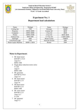
Experiment No.: 1
Department load calculations
Motor in Department:
1. DC shunt motor
KW/HP=1.5/2.0
Amp=8.3
RPM=1500
2. Single phase induction motor series
V=220
Amp=4
RPM=1400
3. DC generator
KW/HP=0.37/0.5
Amp=1.8
4. DC shunt motor
KW/HP=3.7/5
Amp=19
5. DCshunt motor
KW/HP=2.2/3
RPM=1500
6. DC series motor
KW/HP=2.2/3
Amp=12.1
V=220
7. DC generator
Amp=7.1
2. 2
Sanjivani Rural Education Society’s
Sanjivani College of Engineering, Kopargaon-423 603
(An Autonomous Institute, Affiliated to Savitribai Phule Pune University, Pune)
NAAC ‘A’ Grade Accredited
KW/HP=1.6/3
8. DC shut motor
KW/HP=2.2/3.0
V=415
9. Three phase induction motor
KW/HP=2.2/3.0
Amp=4.8
Rpm=1420
10. Three phase slip ring motor (star connected)
KW/HP=3.7/5.0
RPM=1420
Amp=8
V=415
RV=320
11. Three phase induction motor
KW/HP=2.20/3.00
V=415
Amp=4.84
Rpm=1445
12. Three phase induction motor
KW/HP=2.2/3.0
Amp=4.8
Calculations:
No of fan = 65
Wattage(W) = 75
Total Wattage = 65*75 = 4875W = 4.875KW
No of projector = 6
Wattage(W) = 300
Total Wattage = 300*6 = 1800W = 1.8KW
No of computers = 41
Wattage(W) =300
Total Wattage = 41*300 = 12300W = 12.3KW
No of printers = 5
Wattage(W) = 350
Total Wattage = 5*350 = 1750W = 1.75KW
No of exhaust fan = 4
Wattage(W) = 50
3. 3
Sanjivani Rural Education Society’s
Sanjivani College of Engineering, Kopargaon-423 603
(An Autonomous Institute, Affiliated to Savitribai Phule Pune University, Pune)
NAAC ‘A’ Grade Accredited
Total Wattage = 4*50 = 200W = 0.2KW
No of tubelights = 105
Wattage(W) = 20
Total Wattage = 105*20 = 2100W = 2.1KW
No of LED porch light = 34
Wattage(W) = 15
Total Wattage = 34*15 = 510W = 0.51KW
No of Network switch = 1
Wattage(W) = 20
Total Wattage =20W = 0.02KW
Synchronous motor = 5HP*746 = 3.7KW
DC generator = 3KW
Alternator = 2 KVA*0.8 = 1.6KW
DC motor = 3HP*9 = 27KW
Induction motor = 3*6 = 18KW
Capacitor motor = 0.37KW
AC series motor = 0.37KW
DC series motor = 2.2KW
DC shunt motor = 1.5*3 = 4.5KW
Total load = 85KW
Hence Department load = 85KW
4. Sanjivani Rural Education Society’s
Sanjivani College of Engineering, Kopargaon-423 603
(An Autonomous Institute, Affiliated to Savitribai Phule Pune University, Pune)
NAAC ‘A’ Grade Accredited
Experiment No.: 2
Study of Solar Plant Fault Detection Techniques
Abstract
The efficient and uninterrupted operation of solar power plants is vital for maximizing energy
generation. This report explores the fault detection techniquesand strategies employed in solar
plants to identify and address faults promptly, minimizing downtime and optimizing
performance. It begins by outlining common faults in solar plants, including shading, panel
degradation, inverter faults, and wiring issues. The report then delves into various fault
detection techniques such as visual inspections, performance monitoring, data analytics,
thermography, and remote sensing.
Additionally, the report highlights the benefits of implementing automated fault detection
systems in solar plants. These systems integrate data from multiple sources and employ
machine learning algorithms to detect and classify faults in real-time. The ability to
categorize and prioritize faults based on severity facilitates effective maintenance and repairs.
Furthermore, remote monitoring allows for prompt fault detection, reducing downtime and
enhancing safety.
Keywords: Solar Photovoltaic (SPV) Energy, Energy Audit, Grid-Connected SPV system.
1.Introduction:
Solar power plants play a significant role in renewable energy generation, and ensuring their
efficient and uninterrupted operation is crucial. One of the key challenges in solar plant
management is the detection and diagnosis of faults that can hamper the plant's performance.
This report outlines the fault detection techniques and strategies employed in solar plants to
identify and address faults promptly, minimizing downtime and maximizing energy
production.
2. Common Faults in Solar Plants:
Solar plants are susceptible to various types of faults, including but not limited to:
a) Partial or complete shading of solar panels
b) Dust, debris, or soiling on panels
5. Sanjivani Rural Education Society’s
Sanjivani College of Engineering, Kopargaon-423 603
(An Autonomous Institute, Affiliated to Savitribai Phule Pune University, Pune)
NAAC ‘A’ Grade Accredited
c) Panel degradation or damage
d) Inverter faults
e) Wiring or connection issues
f) Sensor or monitoring equipment failures
2.Fault Detection Techniques:
Several techniques are employed in solar plants for fault detection, ranging from manual
inspections to advanced automated monitoring systems. Here are some commonly used
techniques:
a) Visual Inspections: Regular visual inspections by trained personnel can identify obvious
faults such as panel damage, shading, or soiling. However, this method may not be sufficient
for detecting subtle or intermittent faults.
b) Performance Monitoring: Monitoring the performance of individual panels or the entire
plant can provide insights into potential faults. Deviations in power output or efficiency can
indicate the presence of faults.
c) Data Analytics: Advanced data analytics techniques can be applied to the monitoring
data collected from the plant. Machine learning algorithms can analyze large datasets to
identify patterns and anomalies associated with specificfaults.
d) Thermography: Infrared thermography can be used to detect overheating or hotspots in
solar panels, which may indicate electrical faults or degradedcells.
e) Remote Sensing: Satellite imagery or aerial surveys can be used to identify shading
issues, vegetation encroachment, or large-scale panel damage across thesolar plant.
3. Automated Fault Detection Systems:
To enhance fault detection efficiency, automated systems are increasingly being implemented
in solar plants. These systems combine various data sources and employ advanced algorithms
to detect and classify faults in real-time. Key features of automated fault detection systems
include:
6. Sanjivani Rural Education Society’s
Sanjivani College of Engineering, Kopargaon-423 603
(An Autonomous Institute, Affiliated to Savitribai Phule Pune University, Pune)
NAAC ‘A’ Grade Accredited
a) Data Integration: Integration of data from multiple sources such as weather sensors,
power meters, and monitoring equipment to provide a comprehensive view of the plant's
performance.
b) Machine Learning Algorithms: Machine learning algorithms can analyze historical data
to learn normal plant behavior and detect deviations associated with faults. These algorithms
can be trained to identify specific fault patterns andprovide early warnings.
c) Fault Classification: Automated systems can categorize and prioritize faults based on
their severity, enabling maintenance teams to respond effectively.
d) Remote Monitoring: Real-time monitoring of the solar plant allows prompt detection of
faults and minimizes downtime. Remote access to monitoring data enables quick analysis and
decision-making.
4. Benefits of Fault Detection in Solar Plants:
Implementing effective fault detection systems in solar plants offers several benefits,
including:
a) Improved Performance: Timely detection and resolution of faults optimize energy
generation, maximizing the plant's performance and profitability.
b) Reduced Downtime: Early fault detection minimizes downtime by allowing proactive
maintenance and repair, preventing further damage or systemfailures.
c) Cost Savings: By identifying faults early, repair costs can be minimized, and potential
warranty claims can be filed promptly.
d) Enhanced Safety: Fault detection systems contribute to the overall safety of the solar
plant by identifying potential electrical or system issues that could lead to hazardous
situations.
5. Conclusion:
Fault detection in solar plants is essential for ensuring optimal performance, reducing
downtime, and maximizing energy generation. By employing a combination of manual
inspections, performance monitoring, data analytics, and automated fault detection systems,
solar plant operators can promptly identify and address faults, enhancing the plant's reliability
and efficiency. Continuous advancements in monitoring technologies and machine learning
algorithms
7. Sanjivani Rural Education Society’s
Sanjivani College of Engineering, Kopargaon-423 603
(An Autonomous Institute, Affiliated to Savitribai Phule Pune University, Pune)
NAAC ‘A’ Grade Accredited
further improve the accuracy and effectiveness of fault detection systems,contributing to the
growth and sustainability of solar energy.
8. Sanjivani Rural Education Society’s
Sanjivani College of Engineering, Kopargaon-423 603
(An Autonomous Institute,
Affiliated to Savitribai Phule Pune University, Pune)
NAAC ‘A’ Grade Accredited
1
Experiment No.: 3
250 kva Diesel Generator Set
A diesel generator (DG) (also known as a diesel genset) is the
combination of a diesel engine with an electric generator (often an alternator) to
generate electrical energy. This is a specific case of engine generator. A diesel
compression-ignition engine is usually designed to run on diesel fuel, but some
types are adapted for other liquid fuels or natural gas.
Diesel generating sets are used in places without connection to a power
grid, or as an emergency power supply if the grid fails, as well as for more
complex applications such as peak-lopping, grid support, and export to the
power grid.
Diesel generator size is crucial to minimize low load or power shortages.
Sizing is complicated by the characteristics of modern electronics, specifically
non-linear loads. In size ranges around 50 MW and above, an open cycle gas
turbine is more efficient at full load than an array of diesel engines, and far
more compact, with comparable capital costs; but for regular part-loading, even
at these power levels, diesel arrays are sometimes preferred to open cycle gas
turbines, due to their superior efficiencies.
Heavy duty, durable and emission compliant
9. Sanjivani Rural Education Society’s
Sanjivani College of Engineering, Kopargaon-423 603
(An Autonomous Institute,
Affiliated to Savitribai Phule Pune University, Pune)
NAAC ‘A’ Grade Accredited
2
Diesel engine comes with heavy duty features, bigger size camshaft,
optimized turbo-matching and is yet compact in size with optimum power to
weight ratio making it the obvious choice for your long-term power needs.
This genset powered by the reliable diesel engine meets stringent exhaust
emission tests as per CPCB norms without sacrificing fuel efficiency at normal
operating loads.
Standard Scops
Engine
Direct injection, water cooled engine, 6 cylinders, in-line, 4 stroke, rated
at 1500 RPM, conforming to ISO 3046 / BS 5514 has the following
specifications:
- In-line fuel pump with mechanical governor for
180-200 kVA
- In-line fuel pump with electronic governor for 250 kVA
- Optimised turbocharger
- Stainless steel exhaust flexible coupling
- Silencer (Hospital Grade)
- Radiator
- Coolant inhibitor
- Plate-type lube oil cooler
- Spin-on filters - coolant, fuel & lube oil
- Dry-type, heavy duty, replaceable paper element air cleaner with restriction
indicator
- Flywheel housing and flywheel to suit single bearing alternator
- Electrical starter motor
- Battery charging alternator
- First fill lube oil
Alternator
Stamford brushless alternator
10. Sanjivani Rural Education Society’s
Sanjivani College of Engineering, Kopargaon-423 603
(An Autonomous Institute,
Affiliated to Savitribai Phule Pune University, Pune)
NAAC ‘A’ Grade Accredited
3
- Self-excited, self-regulated
- Class ‘H’ insulation
- Salient pole revolving field
- Single bearing
Genset controller PC 1.1
Basic stand-alone Genset control system
Feature laden modular Genset control system
Part of our modular and interchangeable control product line
PMG compatibility and extra inputs and communication capability
(Modbus & CAN), are the major advantages.
Features:
Digital Full Wave SCR AVR for shunt or PMG excitation with torque matching.
Digital Electronic Governing with temperature compensation and Smart Starting.
SAE J1939 Interface to Full Authority Electronic (FAE) engines.
(For future products considering CPCB-II)
Engine Metering: Oil Pressure, Coolant Temperature, Battery
Voltage, Engine Speed
AC Alternator Metering: L-L Voltage and N voltage (phase and average), Current (phase
and total), Volt-Amperes (phase and total), and Frequency.
Engine Protection: Low Lube Oil Pressure, High Coolant Temperature, Over speed, DC
Over/Under/Weak Volts, Fail to Crank/Start, Sensor Failure.
AC Alternator Protection: Over/Under Voltage, Over/Under Frequency, Over Current,
Short Circuit, and Loss of AC Sensing.
Fault Codes and Description on HMI
Data Logging: Engine Hours, Control Hours, Engine Starts and
10 Fault Codes
11. Sanjivani Rural Education Society’s
Sanjivani College of Engineering, Kopargaon-423 603
(An Autonomous Institute,
Affiliated to Savitribai Phule Pune University, Pune)
NAAC ‘A’ Grade Accredited
4
Control Set-Up without PC-based tool (In Power)
Battle Short fault bypass function
Configurable Glow Plug Control
Configurable Cycle Cranking
12- and 24-Volt DC Operation
Easy Wiring connectors for factory connections, terminal blocks for field connections
Configurable Time Delay Start/Stop
Sleep Mode Low power in Off and/or Auto
Rating
Generators must provide the anticipated power required reliably and without damage and
this is achieved by the manufacturer giving one or more ratings to a specific generator
set model. A specific model of a generator operated as a standby generator may only
need to operate for a few hours per year, but the same model operated as a prime power
generator must operate continuously. When running, the standby generator may be
operated with a specified - e.g. 10% overload that can be tolerated for the expected short
running time. The same model generator will carry a higher rating for standby service
than it will for continuous duty. Manufacturers give each set a rating based on
internationally agreed definitions.
These standard rating definitions are designed to allow valid comparisons among
manufacturers, prevent manufacturers from misrating their machines, and guide
designers.
Generator Rating Definitions
Standby Rating based on Applicable for supplying emergency power for the duration
of normal power interruption. No sustained overload capability is available for this
rating. (Equivalent to Fuel Stop Power in accordance with ISO3046, AS2789, DIN6271
and BS5514). Nominally rated.
Typical application - emergency power plant in hospitals, offices, factories etc. Not
connected to grid.
Prime (Unlimited Running Time) Rating: Should not be used for Construction
Power applications. Output available with varying load for an unlimited time. Typical
12. Sanjivani Rural Education Society’s
Sanjivani College of Engineering, Kopargaon-423 603
(An Autonomous Institute,
Affiliated to Savitribai Phule Pune University, Pune)
NAAC ‘A’ Grade Accredited
5
peak demand 100% of prime-rated ekW with 10% of overload capability for emergency
use for a maximum of 1 hour in 12. A 10% overload capability is available for limited
time. (Equivalent to Prime Power in accordance with ISO8528 and Overload Power in
accordance with ISO3046, AS2789, DIN6271, and BS5514). This rating is not
applicable to all generator set models.
Typical application - where the generator is the sole source of power for say a remote
mining or construction site, fairground, festival etc.
Base Load (Continuous) Rating based on applicable for supplying power
continuously to a constant load up to the full output rating for unlimited hours. No
sustained overload capability is available for this rating. Consult an authorized
distributor for rating. (Equivalent to Continuous Power in accordance with ISO8528,
ISO3046, AS2789, DIN6271, and BS5514). This rating does not apply to all generator
set models
Typical application - a generator running a continuous unvarying load, or paralleled with
the mains and continuously feeding power at the maximum permissible level of
8,760 hours per year. This also applies to sets used for peak shaving /grid support even
though this may only occur for say 200 hours per year.
As an example, if in a particular set the Standby Rating was 1000 kW, then a Prime
Power rating might be 850 kW, and the Continuous Rating 800 kW. However, these
ratings vary according to the manufacturer and should be taken from the manufacturer's
datasheet.
Often a set might be given all three ratings stamped on the data plate, but sometimes it
may have only a standby rating or only a prime rating.
Sizing
Typically, however it is the size of the maximum load that has to be connected and the
acceptable maximum voltage drop which determines the set size, not the ratings
themselves. If the set is required to start motors, then the set will have to be at least three
times the largest motor, which is normally started first. This means it will be unlikely to
operate anywhere near the ratings of the chosen set.
Many gen-set manufacturers have software programs that enable the correct choice of a
set for any given load combination. Sizing is based on site conditions and the type of
appliances, equipment, and devices that will be powered by the generator set.
Digital automatic voltage regulator
13. Sanjivani Rural Education Society’s
Sanjivani College of Engineering, Kopargaon-423 603
(An Autonomous Institute,
Affiliated to Savitribai Phule Pune University, Pune)
NAAC ‘A’ Grade Accredited
6
Control Panel: The control panel is manufactured with 14/16-gauge CRCA sheet and is
powder coated for weather-proof and long-lasting finish.
14. Sanjivani Rural Education Society’s
Sanjivani College of Engineering, Kopargaon-423 603
(An Autonomous Institute,
Affiliated to Savitribai Phule Pune University, Pune)
NAAC ‘A’ Grade Accredited
Experiment No. : 04
Study of 11Kv/400 V Pole Mounted Transformer
Abstract
The 11KV/400 v pole mounted transformer offers several advantages in electrical distribution
systems. It is space-efficient, cost-effective, and ensures reliable power distribution with
enhanced voltage regulation. The transformer's flexibility in system layout, easy maintenance,
scalability, and compatibility with smart grid technologies further enhance its value. Overall,
the 11KV/400 v pole mounted transformer provides efficient and sustainable energy
distribution with minimal infrastructure requirements.
1. Introduction:
This report provides an overview of an 11KV/400 v pole mounted transformer, highlighting its
key features, working principles, and applications. The 11KV/400 v pole mounted transformer
is a critical component of electrical distribution systems, enabling the efficient transmission
and distribution of electrical power from high-voltage transmission lines to lower voltage
distribution networks.
2. Transformer Specifications:
The 11KV/400 v pole mounted transformer typically possesses the following specifications:
a) Voltage Ratings: The transformer is designed to handle a primary voltage of 11
kilovolts (kV) and step it down to a secondary voltage of 400 volts (V). These voltage ratings
make it suitable for distribution systems where higher voltage power needs to be stepped down
for local consumption.
b) Power Rating: The power rating of the transformer determines its capacity to deliver
electrical power. It can vary based on specific requirements and applications.
c) Insulation System: The transformer is equipped with an insulation system to
withstand the high voltage levels and ensure safe and reliable operation.
d) Cooling Method: Pole mounted transformers often utilize natural air or oil cooling
methods to dissipate heat generated during operation, ensuring optimal performance and
temperature regulation.
e) Tap Changer: Some transformers may include a tap changer mechanism, allowing
15. Sanjivani Rural Education Society’s
Sanjivani College of Engineering, Kopargaon-423 603
(An Autonomous Institute,
Affiliated to Savitribai Phule Pune University, Pune)
NAAC ‘A’ Grade Accredited
for adjustments in the secondary voltage to compensate for voltage fluctuations or load
variations.
16. Sanjivani Rural Education Society’s
Sanjivani College of Engineering, Kopargaon-423 603
(An Autonomous Institute,
Affiliated to Savitribai Phule Pune University, Pune)
NAAC ‘A’ Grade Accredited
f) Mounting Configuration: The transformer is designed to be mounted on utility
poles, enabling easy installation and integration into overhead distribution systems.
3. Working Principle:
The 11KV/400 v pole mounted transformer operates based on the principles of electromagnetic
induction and voltage transformation. It consists of primary and secondary windings wound
around a magnetic core, which serves as a path for the magnetic flux.
When electrical power is supplied to the primary winding at 11 kV, it creates a varying magnetic
field within the core. This varying magnetic field induces an electromotive force (EMF) in the
secondary winding, resulting in the transformation of voltage from 11 kV to400V.
The transformation ratio between the primary and secondary windings determines the voltage
conversion. The transformer's core and windings are carefully designed to ensure efficient
coupling of magnetic flux and minimize losses during the voltage transformation process.
4. Applications:
The 11KV/400 v pole mounted transformer finds applications in various electrical distribution
systems, including:
a) Residential Areas: The transformer is essential for stepping down high-voltage
power from transmission lines to a lower voltage suitable for residential consumption. It
enables the safe and efficient distribution of electricity to homes, providing power for lighting,
appliances, and other electrical loads.
b) Commercial and Industrial Zones: Commercial complexes, industrial
facilities, and business districts rely on the 11KV/400 v pole mounted transformer for the
distribution of electrical power to meet the demands of commercial and industrial operations.
c) Rural Electrification: The transformer plays a crucial role in rural electrification
projects, where power from higher voltage transmission lines is stepped down to a lower
voltage for rural communities, enabling access to electricity for basic necessities, agriculture,
and rural development.
d) Public Infrastructure: The transformer is used to power public infrastructure such
as street lighting, public transportation systems, and municipal buildings, ensuring reliable
power supply for essential services.
e) Renewable Energy Integration: With the growing adoption of renewable energy
sources such as solar and wind, the 11KV/400 v pole mounted transformer facilitates the
17. Sanjivani Rural Education Society’s
Sanjivani College of Engineering, Kopargaon-423 603
(An Autonomous Institute,
Affiliated to Savitribai Phule Pune University, Pune)
NAAC ‘A’ Grade Accredited
integration of renewable energy into the existing distribution grid, enabling the efficient
distribution of clean power.
5. Advantages:
The 11kv/400 V pole mounted transformer offers several advantages, including:
a) Compact Design: The pole-mounted configuration allows for space-saving
installation on utility poles, making it ideal for distribution systems with limited space
availability.
b) Space-Efficient Design: The pole-mounted configuration of the transformer
allows for installation on utility poles, minimizing the need for additional land or
dedicated structures. This makes it a space-efficient solution for distribution systems
with limited space availability.
c) Cost-Effective Solution: Pole mounted transformers offer cost advantages
compared to other types of transformers. Their compact design, simplified installation
process, and reduced infrastructure requirements contribute to cost savings during
deployment and maintenance.
d) The 11KV/400 v pole mounted transformer offers several advantages in electrical
distribution systems. It is space-efficient, cost-effective, and ensures reliable power
distribution with enhanced voltage regulation. The transformer's flexibility in system
layout, easy maintenance, scalability, and compatibility with smart grid technologies
further enhance its value. Overall, the 11KV/400 v pole mounted transformer provides
efficient and sustainable energy distribution with minimal infrastructurerequirements.
6. Conclusion
The 11KV/400 v pole mounted transformer is a highly advantageous component in electrical
distribution systems. Its space-efficiency, cost-effectiveness, and reliable power distribution
capabilities make it an ideal choice. The transformer's flexibility, easy maintenance, scalability,
and compatibility with smart grid technologies further enhance its value. Overall, it plays a
crucial role in optimizing energy distribution, ensuring reliability, and supporting sustainable
power supply.
18. 1
Sanjivani Rural Education Society’s
Sanjivani College of Engineering, Kopargaon -423 603
(An Autonomous Institute, Affiliated to Savitribai Phule Pune University, Pune)
NAAC ‘A’ Grade Accredited, ISO9001:2015 Certified
Experiment No.: 05
Study of Electrical Control Panel room
Abstract:
This comprehensive report explores the topic of powerhouse electricity in colleges, focusing on
the vital role of reliable and sustainable power supply in campus facilities. The report delves into
the infrastructure of college powerhouses, including generators, transformers, and distribution
systems. It examines various power generation methods, such as fossil fuels, renewable energy
sources, and combined heat and power systems, while highlighting the growing trend towards
renewable energy adoption.
Introduction:
Provide an overview of the importance of electricity in colleges and universities.
Explain the significance of a reliable and sustainable power supply.
Introduce the concept of a college powerhouse and its role in supplying electricity to
campus facilities.
Powerhouse Infrastructure:
Describe the physical infrastructure of a college powerhouse.
Discuss the main components, such as generators, transformers, switchgear, and
distribution systems.
Explain the interconnection between the powerhouse and the main power grid.
Power Generation:
Explore different methods of power generation commonly used in college powerhouses,
such as fossil fuels, renewable energy sources, and combined heat and power (CHP)
systems.
Discuss the advantages and disadvantages of each method.
Highlight the growing trend toward renewable energy adoption in college campuses.
Power Management and Distribution:
Explain the process of power management and distribution within a college powerhouse.
Discuss the importance of load balancing, voltage regulation, and backup power systems.
Explore the use of smart grids and advanced technologies for efficient energy management.
Energy Conservation and Efficiency:
19. Emphasize the importance of energy conservation and efficiency in college campuses.
Discuss various strategies and initiatives for reducing energy consumption, such as energy-
efficient lighting, HVAC systems, and smart building technologies.
Highlight the benefits of energy-saving practices, including cost savings and environmental
sustainability.
Sustainability Initiatives:
Explore sustainability initiatives undertaken by colleges to reduce their carbon footprint.
Discuss the integration of renewable energy sources, such as solar panels and wind
turbines, into the powerhouse infrastructure.
Highlight case studies of colleges implementing successful sustainability projects.
Challenges and Solutions:
Identify common challenges faced by college powerhouses, such as aging infrastructure,
rising energy costs, and regulatory compliance.
Discuss potential solutions to overcome these challenges, such as infrastructure upgrades,
energy audits, and collaboration with utility companies.
Address the role of research and innovation in developing sustainable energy solutions for
college campuses.
Case Studies:
Present case studies of colleges or universities known for their innovative approaches to
powerhouse electricity management.
Discuss their strategies, outcomes, and lessons learned.
Future Trends:
Explore emerging trends and technologies that could shape the future of powerhouse
electricity in colleges.
Discuss advancements in energy storage, microgrids, and demand response systems.
Address the potential impact of electric vehicles and their integration into college power
systems.
Conclusion:
This report underscores the importance of reliable and sustainable electricity in college campuses
and advocates for ongoing efforts to improve energy efficiency and promote renewable energy
adoption in college powerhouses. The findings highlight the significance of college powerhouses
as key components in supporting the educational mission while contributing to environmental
sustainability.
20. 1
Sanjivani Rural Education Society’s
Sanjivani College of Engineering, Kopargaon-423 603
(An Autonomous Institute, Affiliated to Savitribai Phule Pune University, Pune)
NAAC ‘A’ Grade Accredited
Experiment No.: 06
Electricity bill calculation for one month
21. 2
Sanjivani Rural Education Society’s
Sanjivani College of Engineering, Kopargaon-423 603
(An Autonomous Institute, Affiliated to Savitribai Phule Pune University, Pune)
NAAC ‘A’ Grade Accredited
Calculation of electricity bill for 1 month assume following data:
I. Fixed charges – 105
II. Transmission charges – 1.35 per/unit
III. Fuel adjustment charges
For 100 – 0.65 paise
For above 100 to 300 – 1.42 paise
IV. Electricity charges – 16%
Solution- Consider electricity bill to be calculated for 98 units.
1 unit is considered as 3.32
Electricity charges (0 to 100 = 3.36 & 100 to 300 = 7.34)
Power size = Total unit * Per unit cost
= 98*3.36
= 329.28
Electricity transmission = Total unit * 1.35
= 98*1.35
= 132.30
Fuel adjustment = 98*0.65
= 63.70
Electricity charges @ 16% = (329.28+ 105.00+132.30+63.70) * 0.16
= 630.28 * 0.16
= 100.84
Total Electricity Bill = 630.28 + 100.84
= 731.12
22. Sanjivani Rural Education Society’s
Sanjivani College of Engineering, Kopargaon-423603
(An Autonomous Institute, Affiliated to Savitribai Phule Pune University, Pune)
NACC ‘A’ Grade Accredited, ISO 9001:2015 Certified
1
Experiment No.: 07
Study of Cables
Introduction
The study on cables in power systems aims to explore the various aspects of cables used in
transmitting electrical power. Cables play a critical role in the reliable and efficient delivery of
electricity from power generation sources to end consumers. This report provides an overview
of the study conducted on power system cables, including their types, characteristics,
applications, challenges, and advancements.
Types of Cables
There are several types of cables used in power systems, each designed for specific
applications. The commonly used cable types include:
1. Power Cables
These cables are used for high-voltage transmission and distribution of electrical power over
long distances.
2. Control Cables
23. Sanjivani Rural Education Society’s
Sanjivani College of Engineering, Kopargaon-423603
(An Autonomous Institute, Affiliated to Savitribai Phule Pune University, Pune)
NACC ‘A’ Grade Accredited, ISO 9001:2015 Certified
2
They are used for transmitting signals for controlling and monitoring electrical equipment.
24. Sanjivani Rural Education Society’s
Sanjivani College of Engineering, Kopargaon-423603
(An Autonomous Institute, Affiliated to Savitribai Phule Pune University, Pune)
NACC ‘A’ Grade Accredited, ISO 9001:2015 Certified
3
3. Instrumental Cables
These cables carry low voltage signals from instruments and sensors for measurement and
control purposes.
4. Fiber optic Cables
Fiber optic cables transmit data using light signals, enabling high-speed communication and
control in power systems.
Cable Characteristics
Cables in power systems possess specific characteristics that make them suitable for their
intended applications.
Some important characteristics include:
a. Voltage rating: Cables are designed to handle specific voltage levels, ranging from low
voltage to extra-high voltage.
b. Current carrying capacity: Cables should be capable of carrying the expected electrical
current without overheating or exceeding their ampacity.
25. Sanjivani Rural Education Society’s
Sanjivani College of Engineering, Kopargaon-423603
(An Autonomous Institute, Affiliated to Savitribai Phule Pune University, Pune)
NACC ‘A’ Grade Accredited, ISO 9001:2015 Certified
4
c. Insulation and shielding: Cables are insulated to prevent current leakage and protect against
electrical hazards. Shielding minimizes electromagnetic interference.
d. Temperature rating: Cables should withstand the operating temperatures without
degradation or insulation failure.
e. Environmental resistance: Cables should be resistant to moisture, chemicals, and other
environmental factors to ensure long-term reliability.
Applications of Cables
Cables find extensive applications in power systems, including:
a. Overhead transmission lines: Power cables are used to transmit electricity over long
distances from power plants to distribution substations.
b. Underground distribution networks: Cables are employed to distribute power within
urban areas, underground or in tunnels.
c. Interconnecting grids: Cables are used to connect different power grids or regions,
facilitating power exchange and enhancing grid stability.
d. Renewable energy integration: Cables enable the connection of renewable energysources
such as wind farms and solar parks to the main power grid.
e. Industrial applications: Cables are used in industrial settings for power distribution,
machinery control, and instrumentation.
Challenges and Advancements
The study on power system cables has identified several challenges and advancements in the
field.
Some key points include:
a. Aging infrastructure: Many power grids have aging cable infrastructure, requiring
maintenance and replacement to ensure reliable power delivery.
b. Fault detection and monitoring: Advanced techniques such as online monitoring and
diagnostic systems are being developed to detect cable faults and predict failures.
c. High-temperature superconducting cables: Research is ongoing to develop high-
temperature superconducting cables that can transmit electricity with minimal resistance,
improving efficiency.
d. Enhanced insulation materials: Novel insulation materials with improved thermal and
electrical properties are being explored to enhance cable performance and reduce losses.
e. Smart grid integration: Cables equipped with sensing and communication capabilities
enable the integration of power systems into smart grids, enabling better control and
monitoring.
26. Sanjivani Rural Education Society’s
Sanjivani College of Engineering, Kopargaon-423603
(An Autonomous Institute, Affiliated to Savitribai Phule Pune University, Pune)
NACC ‘A’ Grade Accredited, ISO 9001:2015 Certified
5
Conclusion
The study on cables in power systems highlights their crucial role in the reliable and efficient
transmission of electrical power. Understanding the various cable types, characteristics,
applications, challenges, and advancements is essential for ensuring the optimal operation and
maintenance of power systems. Further research and development efforts are required to
address the challenges and harness the potential advancements in power system cables for a
sustainable and resilient energy future.
27. Sanjivani Rural Education Society’s
Sanjivani College of Engineering, Kopargaon-423 603
(An Autonomous Institute, Affiliated to Savitribai Phule Pune University, Pune)
NAAC ‘A’ Grade Accredited
1
Experiment No. : 08
Study of Underground Fault Detection System Using Thumper
Test
Abstract:
The Underground Fault Detection System (UFDS) plays a critical role in maintaining the
reliability and safety of underground electrical distribution networks. This report explores the
application of the Thumper Test, a widely used technique in UFDS, for detecting faults in
underground cables. The Thumper Test involves injecting a high-voltage pulse into the cable
and analyzing the reflections to determine the fault location. This abstract provides a brief
overview of the UFDS and highlights the key steps involved in the Thumper Test. The
advantages and limitations of this technique are also discussed. The Thumper Test offers non-
destructive fault detection, fast and accurate results, and efficient repair processes. However,it
may have limitations in detecting certain fault types and requires skilled operators for
interpretation. Overall, the UFDS utilizing the Thumper Test proves to be a valuable solution
for effective fault detection and localization in underground electrical networks.
1. Introduction
The Underground Fault Detection System (UFDS) plays a vital role in the efficient operation
and maintenance of underground electrical distribution networks. Identifying faults accurately
and quickly is crucial to minimize downtime, prevent damage, and ensure the safety of
personnel. One effective technique used in fault detection is the Thumper Test. This report
aims to provide an overview of the UFDS and discuss the application of the Thumper Test for
underground fault detection.
2. Underground Fault Detection System (UFDS)
The UFDS is a comprehensive system that combines various technologies and methods to
detect and locate faults in underground electrical cables. It comprises both hardware and
software components that work together to monitor, analyze, and diagnose faults. The main
objectives of a UFDS include:
a. Fault detection: Detecting the presence of a fault in the underground cable system.
b. Fault location: Determining the precise location of the fault within the cable network.
c. Fault classification: Identifying the type of fault, such as a short circuit, open circuit, or
insulation fault.
d. Fault diagnosis: Analyzing the fault characteristics to assess the severity and potential
causes.
28. Sanjivani Rural Education Society’s
Sanjivani College of Engineering, Kopargaon-423 603
(An Autonomous Institute, Affiliated to Savitribai Phule Pune University, Pune)
NAAC ‘A’ Grade Accredited
2
e. Alarm generation: Alerting the system operators or maintenance personnel about the fault
occurrence.
29. Sanjivani Rural Education Society’s
Sanjivani College of Engineering, Kopargaon-423 603
(An Autonomous Institute, Affiliated to Savitribai Phule Pune University, Pune)
NAAC ‘A’ Grade Accredited
3
3. Thumper Test for Underground Fault Detection
The Thumper Test, also known as cable fault location or cable fault prelocation, is a widely
used technique in UFDS for locating faults in underground electrical cables. It involves
inducing a high-voltage pulse into the cable and monitoring the response to identify the fault
location. The key steps involved in the Thumper Test are as follows:
a. Cable Preparation: Prior to conducting the Thumper Test, the cable section under test is
prepared by ensuring it is properly isolated from the rest of the system.
b. Pulse Generation: A high-energy pulse, typically in the kilovolt range, is generated using
specialized thumper equipment. The pulse is then injected into the cable under test.
c. Reflection Measurement: Sensors or detectors placed at various points along the cable
capture the reflections caused by impedance changes due to the fault. The time and amplitude
of these reflections provide valuable information about the fault location.
d. Analysis and Interpretation: The captured reflection data is analyzed using signal
processing techniques to determine the fault location. Time-domain reflectometry (TDR) and
frequency-domain reflectometry (FDR) are commonly employed for data analysis.
e. Fault Location Estimation: By analyzing the reflection data, the distance to the fault from
the test point can be estimated. Additional measurements and calculations may be required to
pinpoint the fault location more precisely.
4. Advantages and Limitations of Thumper Test
The Thumper Test offers several advantages in underground fault detection:
a. Non-Destructive: The Thumper Test is a non-destructive technique, meaning it does not
cause any damage to the cable or surrounding infrastructure during fault detection.
b. Fast and Efficient: The Thumper Test can quickly locate faults, allowing for prompt repairs
and reduced downtime.
c. High Accuracy: The reflection data captured during the Thumper Test provides accurate
information about the fault location, helping technicians focus their efforts efficiently.
However, the Thumper Test has certain limitations:
a. Limited to Certain Fault Types: The Thumper Test is most effective for detecting resistive
faults, such as short circuits and open circuits, but may not be as effective for detecting
insulation faults.
b. Requires Skilled Operators: Interpreting the reflection data and accurately locating faults
require trained personnel familiar with the Thumper Test technique.
30. Sanjivani Rural Education Society’s
Sanjivani College of Engineering, Kopargaon-423 603
(An Autonomous Institute, Affiliated to Savitribai Phule Pune University, Pune)
NAAC ‘A’ Grade Accredited
4
5. Conclusion
The Underground Fault Detection System, utilizing the Thumper Test, is a valuable tool for
efficient fault detection and localization in underground electrical distribution networks. The
Thumper Test's ability to accurately identify faults.