
Recommended
More Related Content
What's hot
What's hot (20)
Similar to Automobile Engineering Unit 3 - Anna University
Similar to Automobile Engineering Unit 3 - Anna University (20)
Recently uploaded
Recently uploaded (20)
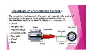
Automobile Engineering Unit 3 - Anna University
- 3. CLUTCH • A clutch is a mechanical device that engages and disengages the power transmission, especially from driving shaft to driven shaft.
- 4. • When clutch engaged, the engine will be connected to the transmission and power flows from engine to rear. • When clutch is disengaged by pedal the engine will be disengaged from the transmission. Power does not flow to rear wheels while the engine is still running.
- 5. Principles of operation of friction clutch: Clutch working on the principle of friction. Shaft 1 engaged with flange A is rotated at N rpm, and shaft 2 with the flange B is keyed with driven shaft.
- 6. Requirements of clutch: a) Transmission of torque. b) Gradual engagement. c) Dissipation of heat. d) Dynamic balancing. e) Size of the clutch. f) Vibration damping.
- 8. Single plate clutch consists of a Flywheel Pilot bearing Clutch plate or disc plate Pressure plate Clutch cover assembly Release mechanism Clutch shaft
- 9. I) Flywheel: Is the mounting surface for the clutch. Pressure plates bolts to the flywheel face. Clutch disc is clamped and held against the flywheel by the spring action of the pressure plate. Face of the flywheel is made of iron for better heat dissipates.
- 10. II) Pilot bearing: Is pressed into the end of the crankshaft to support the end of the transmission input shaft. Pilot bearing is a solid bronze bushing, but is also may be a roller or ball bearing. End of the transmission input shaft has a small journal, this journal slides inside the pilot bearing. It prevents the transmission shaft and clutch disc from up and down movement.
- 11. III) Clutch plate: Important driving member of a single plate clutch. B/w flywheel and pressure plate. It consists of a central hub machined with internal splines. Cushion drive clutch plate provide a damping action against the torsional vibrations and the variation of the driving torque between engine and transmission. Damping action achieved by coupling the splined center hub to the driven plate with the help of flexible mounting. Torsion spring – cushion the clutch engagement.
- 12. IV) Pressure plate. Made of special cast iron, heaviest part of the clutch assembly. Main function- establish even contact with the driven plate facing through which the pressure springs can exert a sufficient force to transmit the full torque of the engine. Pressure plate presses the clutch plate on to the flywheel from its machined surface.
- 13. V) Clutch cover assembly: Is bolted to the flywheel. it consist of pressure plate, release lever mechanism, clutch cover, and pressure springs. Clutch plate revolves with the flywheel, when the clutch is disengaged, the flywheel as well as the pressure plates will be forced to rotate independently. Release mechanism used to release the clutch.
- 14. • Release mechanism. • Clutch shaft. • Working. • Advantages: Easy to change gears than a cone type. It is reliable than a cone clutch. • Disadvantages: More force to release. Space required is more
- 15. Multi-Plate clutch • Mostly used in heavy and racing cars for transmitting high torque. • No of clutch plates is on increased, the friction surface will be also increased. • Increase in friction surface, increases the capacity of clutch to transmit more torque. • Wet or dry type; when clutch operated in oil bath is called as wet. Mostly wet clutches used in automatic transmission system. • Construction is similar to single plate clutch type. • One set of plates are slides in grooves on the flywheel and other one set of plates are slides on splines on the pressure plate hub. • Working same as single plate clutch.
- 17. Cone clutch • Contact surface are in the form of cone. • Its contain outer and inner cone leather facings. • Outer cone is fixed with driving shaft and inner cone is splined on the driven shaft. • When clutch engaged inner cone is fully inside the outer cone, it will make the friction surfaces are in perfect contact. It is done by the pressure springs. • Now the torque transmitted. • Clutch pedal pressed, inner cone slides against the spring force and the clutch is disengaged.
- 18. Advantages: 1. Normal force acting on the contact surface is larger than the axial force, which reduces the effort required to operate the clutch. Disadvantages: 1. Need heavy force to disengage the clutch. 2. Possibility for more wear
- 19. Centrifugal Clutch • This clutch controlled by the engine speed. • When the engine speed falls down, the clutch will automatically disengage. • When speed rises above the predetermined value the clutch is engaged. If the speed increases, centrifugal force will increase. • have two members; driving and driven • Driven member is just a drum which enclose the driving member. • The driving member consists of a spider, shoes having friction lining at outer end and springs. • Shoes are attached to the spider by means of springs.
- 20. •The driving member rotates with the engine shaft. •As engine speed increases the shoes inside the driving member drum will fly outward due to centrifugal force and come into contact with the inner surface of the driven member. •The increase in centrifugal force due to higher engine speed binds the driving member with the driven member.
- 21. Diaphragm clutch • Similar to a single plate clutch except the diaphragm springs. • No release lever required and the spring itself acts as a series of levers. • Pressure of the spring increases till the spring reaches to its flat position. • No need for heavy pedal pressure to hold the clutch out. Advantages: • Require lower operating effort. • Constant and uniform plate on the driven plate. • It provide accurate balancing at all times. • Compact design, clutch housing required is quite short
- 23. Positive clutch • It is generally used to lock two shafts together. • It consists of a sliding sleeve fitted with the driving member.
- 24. Hydraulic Clutch Operated under the following situations. 1. When the difficulty to run rods and or able from the foot pedal to clutch. 2. The fore required by the driver to release the clutch becomes more excessive.
- 25. • Consists of a master cylinder, slave cylinder and an oil reservoir. • Clutch pedal is pressed – the fluid under pressure from the master cylinder reaches the slave cylinder. • Slave cylinder mounted on the clutch itself. • The fluid actuates the slave cylinder push rod which further operates the clutch release fork.
- 27. Vacuum clutch
- 28. Vacuum clutch • The vacuum clutch is operated by the vacuum existing in the engine manifold. • It consists of a vacuum cylinder with piston, solenoid operated valve, reservoir and a non-return valve. • The reservoir is connected to the engine manifold through a non return valve. Vacuum cylinder is connected to the reservoir through solenoid operated valve. • The solenoid is operated from the battery and the circuit incorporates a switch which is placed in the gear lever. The switch is operated when the driver holds the lever to change gears. • When the throttle is wide opened, the pressure in the inlet manifold increases due to which the non-return valve closes, isolating the reservoir from the manifold. Thus a vacuum exists in the reservoir all the time.
- 29. • In the normal operation, the switch in the gear lever remains off, the solenoid operated valve remains in its bottom position. • In this positions the atmospheric pressure acts on both the side of the vacuum cylinder, because the vacuum cylinder is open, so also atmosphere though a vent. • When the driver holds the lever to change the gear, the switch is closed; energizing the solenoid which pulls the valve up. This connects one side of vacuum cylinder to the reservoir. • Due to the difference of pressure on the vacuum cylinder piston, it moves. This movement of the piston is transmitted by a linkage to the clutch, causing it to disengage. • When the driver is not operating the gear lever, the switch is open and the clutch remains engaged due to the force of springs.
- 30. Fluid Flywheel • Known as fluid coupling which couples the driving member with driven member through fluid. • Driving member connected with flywheel and driven member connected with transmission shaft. • Driven member is free to slide on the transmission shaft. Two rotors are filled with fluid of required viscosity.
- 31. • When engine started, driving member ‘impeller’ starts to move inside the housing containing oil. • Pockets of moving driving member are completely filled with oil. Due to this, the centrifugal force forces the oil outward radially. • Splashed oil will strike the pockets of the driven member. Hence it is forced to move in the same direction. • When engine speed increases, the oil coming from the pocket of the driving member strikes the pockets of the driven member with greater force.
- 33. Advantages: • It gives smoother power take up. • Fluid in the coupling behaves as a cushioning agent between engine and gearbox to absorb shocks during breaking. • No wear on moving parts. • No maintenance, except oil level • Simple in design. • No skill is required for operating.
- 34. Torque converter gearbox • Construction is same as fluid coupling, additional stationary member called ‘stator’ is attached. • Torque converter increases the torque in the ratio of 2:1 to 3:1. Main parts are 1. Impeller or driven member 2. Turbine or driving 3. Stator
- 36. • Due to the rotation of driving member oil is pushed in the outward direction by centrifugal force. • Turbine started to rotate when the engine starts. • First, the oil from turbine is pushed into the impeller due to high centrifugal force at the turbine. • At that time the impeller is held stationary. • By this, the oil gets high kinetic energy from the engine through the turbine. • Flow of high energy oil creates enough force that tends to rotate the impeller.
- 37. • Impeller blade angle changes the direction of the oil flow to come out of the impeller at centre. • Now the direction of oil is entirely backward. • If it will enter the turbine directly it will push the turbine in opposite direction. • Oil from the impeller is made to strike a stationary member to avoid this dragging action on the turbine. • Stator changes the oil direction suitably to leave the oil from the stator striking the turbine in the same direction of turbine turning. • Oil is thrown back by the turbine into the impeller edges. • This continuous process makes the torque on the impeller to increase which is called torque multiplication.
- 38. • The maximum torque multiplication is possible when the impeller is stationary and turbine is running fast with the engine speed. • When the vehicle starts to move, the impeller speed will start to increase. But the torque multiplication will gradually reduce due to decrease of the difference in both impeller and turbine speed. • When the turbine speed becomes equal to the impeller speed, the torque multiplication will become unity. ( Direct gear)
- 39. Propeller shaft • Propeller shaft is connected between transmission shaft and input shaft of the differential. • Called as driveline shaft or drive shaft. • Length and short shaft. • Transmission output shaft and the input shaft to the rear axle housing are in different planes.
- 40. • Whenever the rear wheels absorb irregulations in the road, the rear axle housing will move up and down by compressing and expanding the suspension system. • Then the angle b/w transmission output shaft and propeller shaft is changed. • Length occupied by the propeller shaft will change. • Defined as the distance between transmission shaft and pinion shaft of the differential.
- 41. Functions of the propeller shaft: • It transmits rotary motion of the gearbox output shaft to the differential. • It transmits motion at an angle which frequently varies. • It allows some changes in length between gearbox and rear axle. Propeller shaft construction: a. Variation of angle and length are considered. b. Propeller shaft is made of two shafts and two types of flexible joints such as slip joint and two universal joints. c. Shafts are thin walled steel tubes. Dia--50mm to 70mm. Thickness varies from 1.5mm to 7.5mm. Tubular section…
- 42. d. Universal joints are fitted at the end of the shaft. e. If any variation in the inclination of the propeller shaft, the universal joint will take care. f. If the distance between transmission shaft and pinion shaft is more, one or more intermediate propeller shafts are used. g. Intermediate shaft is always supported by bearing unit. The bearing unit is consists of runner pad and ball bearing
- 43. Types: 1. Open type: • Used in heavy commercial vehicle, has tubular cross section but it is not enclosed. • Two universal joints are connected with each end. One with gearbox main shaft another one with pinion of differential. • Longer, so it is made up of two portions. • Propeller shaft connected to the frame member with the help of bearings.
- 44. 2. Enclosed type: • This type propeller shaft is of a solid cross-section. • This propeller shaft is supported by roller bearings inside torque tubes. • Diameter is small when compare to open type. • The torque and twisting motion of rear axle casing are resisted by this shaft when the brake is applied.
- 45. Slip joints • Propeller shaft is inclined towards down from the transmission shaft. • Propeller shaft will also be shortened and lengthened again when the axle rises as the rear springs are compressed and at the time the axle returns to its original position. • Slip joint is always used between propeller shaft and universal joints.
- 46. • Slip joints compensate the change in length and it helps to transmit power from engine to rear axle at the same time. • In torque tube drive, no need for a slip joints. • The joint consists of a male splined end of the main shaft to slide in corresponding grooves with the female member of the joint. • The female part is integral with the universal joint hub.
- 47. Universal joints • Transmission of power under varying condition is impossible without using a flexible device. • Universal joints are mainly used to make a flexible connection between two rigid shafts at an angle. • It used to connect propeller shaft with the gear box shaft to transmit rotary motion. Universal joint consists of two yokes. These two yokes are connected to each end of the shaft.
- 48. Types of universal joints Variable velocity joints: • Both the driven and driving shafts do not turn at the same speed. • The driven and driving shafts should be placed in a straight line to turn at the same speed through each part of a revolution. • Practically is not possible in any automobile. The drive shaft is always inclined. • If there is an angle b/w driven and driving shaft, the driven shaft will turn lower than driving shaft through half a revolution and it is faster than driving shaft through the other half revolution. • Speed variation in the driven shaft increase in flex angle of the universal joint.
- 49. Types of variable joints are,: i) Cross or spider type: Two yokes in which one is connected to the driving shaft and the other one is connected to the driven shaft at right angle to each other by a cross or spider. Needle type bearings are mounted b/w yokes and cross ends.
- 50. ii) Ring type: This type of joint uses a flexible ring, is made of one or more rings of rubber to provide enough strength. It smoothens the torque fluctuations and it needs no lubrication.
- 51. iii) Ball and trunion type: • A combination of both universal and slip joint. • A pin is connected in the end of universal joint shaft. • Each end of the pin has a ball mounted on needle bearings. • Heavy spring resists excessive longitudinal movement of shaft. • Power transmitted through the trunion, balls and cross shaft. • Bending moment occurs in one direction by rolling action of balls and other direction by moving balls lengthwise in grooves. • Open end of the shaft is covered by leather or rubber boot cover.
- 52. Needle Bearing
- 54. Constant velocity joints: • The driven shaft is turned at the same speed as the driving shaft turns through each part of revolution at any degree of flex. • Mainly used in front drive axle for transmitting power through a large angle required. Types,: i) Rzeppa:
- 55. • It consists of spherical inner and outer ball races having grooves cut parallel to shafts. • Steel balls are placed in grooves on the spherical races. • The torque transmission is done from one race to another ball. • The circular pattern of balls causes both shafts to turn at the same velocity. ii) Bendix weiss:
- 56. • The principle of driving through balls held in a circle around a sphere is used here. • Four number of driving balls are used. • A fifth ball is placed b/w two yokes as an inner race. • Driving balls are arranged in the same manner to rzeppa joint. iii) Tracta:
- 57. The Tracta joint works on the principle of the double tongue and groove joint. It consist only four individual parts: the two forks (yokes, one driving and one driven) and the two semi- spherical sliding pieces which interlock in a floating (movable) connection. Both circular segment and floating action of two yokes provide a constant velocity joint.
- 58. Why the Differential gear is used? Wheels receive power from the engine via a drive shaft. The wheels that receive power and make the vehicle move forward are called the drive wheels. The main function of the differential gear is to allow the drive wheels to turn at different rpms while both receiving power from the engine.
- 59. Consider these wheels, It is clear that the left wheel has to travel a greater distance compared to the right wheel. This means that the left wheel has to rotate at a higher speed compared to the right wheel. If these wheels were connected using a solid shaft, the wheels would have to slip to achieve the turn. This is exactly where a differential comes in handy. The ingenious mechanism in a differential allows the left and right wheels to turn at different rpms, while transferring power to both wheels.
- 60. Parts of a Differential Power from the engine is transferred to the ring gear through a pinion gear. The ring gear is connected to a spider gear.
- 62. The spider gear lies at the heart of the differential, and special mention should be made about its rotation. The spider gear is free to make 2 kinds of rotations: one along with the ring gear (rotation) and the second on its own axis (spin).
- 63. •The spider gear is meshed with 2 side gears. both the spider and side gears are bevel gears. •From the drive shaft power is transferred to the pinion gear first, and since the pinion and ring gear are meshed, power flows to the ring gear. •As the spider gear is connected with the ring gear, power flows to it. •Finally from the spider gear, power gets transferred to both the side gears.
- 64. Differential Operation The vehicle moves straight In this case, the spider gear rotates along with the ring gear but does not rotate on its own axis. So the spider gear will push and make both the side gears turn, and both will turn at the same speed. In short, when the vehicle moves straight, the spider-side gear assembly will move as a single solid unit. Fig.6 While the vehicle moves straight, the spider gear does not spin; it pushes and rotate the side gears
- 65. The vehicle takes a right turn Now consider the case when the vehicle is taking a right turn. The spider gear plays a pivotal role in this case. Along with the rotation of the ring gear it rotates on its own axis. So, the spider gear is has a combined rotation.
- 66. •When properly meshed, the side gear has to have the same peripheral velocity as the spider gear. •Both gears should have the same pitch line velocity. •When the spider gear is spinning as well as rotating, peripheral velocity on the left side of spider gear is the sum of the spinning and rotational velocities. •But on the right side, it is the difference of the two, since the spin velocity is in the opposite direction on this side. •This means the left side gear will have higher speed compared to the right side gear. •This is the way the differential manages to turn left and right wheels at different speeds.
- 67. The vehicle takes a left turn While taking a left turn, the right wheel should rotate at a higher speed. By comparing with the previous case, it is clear that, if the spider gear spins in the opposite direction, the right side gear will have a higher speed.
- 68. Drawback of a Standard Differential The differential we have gone through so far is known as open or standard differential. It is capable of turning the wheels at different rpm, but it has got one major drawback. Consider a situation where one wheel of the vehicle is on a surface with good traction and the other wheel on a slippery track. In this case a standard differential will send the majority of the power to the slippery wheel, so the vehicle won’t be able to move. To overcome this problem, Limited Slip Differentials are introduced.
- 69. One way to overcome this problem is to limit the independency or relative motion between the left and right axles.Limited slip differentials are introduced for this purpose. One of the most commonly used LSD technology is clutch-pack based.
- 70. Constructional Features of LSD The basic components of a standard differential are shown below. It has got pinion gear, ring gear, case, spider gears and side gears. •Apart from its basic components a Limited slip differential has got a series of friction and steel plates packed between the side gear and the casing. •Friction discs are having internal teeth and they are locked with the splines of the side gear. •So the friction discs and the side gear will always move together.
- 71. •Steels plates are having external tabs and are made to fit in the case groove. So they can rotate with the case. •If any of the clutch pack assembly is well pressed, the frictional force within them will make it move as a single solid unit. •Since steel plates are locked with the case and friction discs with the side gear, in a well pressed clutch pack casing and the clutch pack will move together. •Space between the side gears is fitted with a pre-load spring. Pre load spring will always give a thrust force and will press clutch pack together.
- 72. Separating action of Bevel gears You can note that spider and side gear are bevel gears. It has got one specialty. When torque is transmitted through a bevel gear system axial forces are also induced apart from the tangential force. The axial force tries to separate out the gears.
- 73. You can note that side gear and axle are 2 separate units. The side gear has got a small allowance for axial movement. So during high torque transmission through spider-side gear arrangement, a high separating thrust force is also transmitted to the clutch pack. This force presses and locks the clutch pack assembly against wall of the casing.
- 74. Working of Limited Slip Differential Now back to the initial problem. Since one wheel is on a high traction surface, the torque transmitted to it will be higher. So the thrust force developed due to the bevel gear separation action also will be high at that side. Thus clutch pack at high traction wheel side will be pressed firmly and clutch pack will be locked. So power from the differential casing will flow directly to high traction axle via clutch pack assembly.
- 75. On the other hand clutch pack on the low traction wheel side is not engaged yet, so power flow will be limited to that side. So the vehicle will be able to overcome the traction difference problem. •However while taking a turn the LSD can act like a normal differential. •In this case thrust force developed due to bevel gear separation action won’t be that high. •So the plates in clutch pack will easily overcome frictional resistance and will be able to slip against each other. •Thus the right and left wheel can have different speed just like an open differential.
- 76. Cone clutch differential: •In place of clutch packs, the friction lined cones are used. •The operation is similar to clutch plate differential. •Preload spring and side gear pressures force the cone into a depression in the differential case. •Therefore, the side gear sends power to the wheel with the most traction.
- 77. Rear axle Dead axles: A dead axle, also called lazy axle, is not part of the drivetrain but is instead free-rotating. The rear axle of a front- wheel drive car is usually a dead axle. Many trucks and trailers use dead axles for strictly load- bearing purposes. Live axles: A live axle is a type of beam axle in which the shaft transmits power to the wheels.
- 78. Rear axle casing Split type axle casing: In this type of axle split shaft are used with the central housing contain the differential gear and it is fitted with a tube on each side to carry the half axles and bearing.
- 79. Banjo type axle casing •This type of axle is a single shaft and final drive assembly is carried in a separate casing which is bolted to the axle housing. •The banjo construction is often used for smaller and lighter vehicle.
- 80. Carrier type axle casing: This type of casing is more rigid than a banjo type and is often employed to support a hypoid gear. The final drive assembly is installed in a rigid malleable cast iron carrier, into which the axle tubes are pressed and welding.
- 81. Types of loads acting on rear axles • Weight of the body • Side thrust • Driving thrust
- 82. Types of rear axles 1. Semi floating axle: • An axle in which the shaft has to take the entire load. • Wheel hub directly connected to the axle • In this type all the loads are taken by the axle shaft. • The whole load acts on the shaft and shaft has a tendency to shear at a particular point. • Semi floating axle is simplest and cheapest but for a given torque they have to be of larger dia.
- 83. 2. Full floating axle: • Used for heavy vehicle. • The axle shafts have flanges at the outer end which are connected to flanged sleeve by means of bolts. • Two tapper roller bearing supporting for take up any side load. • The axle shaft carry only the driving torque. So their failure does not affect the wheels.
- 84. 3. Three quarter floating axle: •Combination of full and semi floating bearing. •Axle shaft maintain the alignment of the wheel. •Construction of the inner end axle shaft is similar to a semi- floating axle. •It has only one bearing at the outer end and it will carry some bending stresses.
- 86. Rear axle drives 1. Hotchkiss drive: • It consists of a propeller shaft, two longitudinal leaf springs. • Propeller shaft has a slip joint. • Front end of leaf spring is connected to hinged to the frame and the rear end is connected with the frame by swinging shackles. • The rear end torque is borne by springs. It gets deflected while driving and also braking. • The deflection helps to improve flexibility and damp shocks.
- 88. 2) Torque tube drive: • A hollow tube encloses the propeller shaft. • The tube is rigidly connected to the differential housing at one end. The other end of the tube is connected to the gearbox by flexible ball and socket. • The driving thrust and rear end torque are carried by a hollow tube. • The tube is used in bearings to support the propeller shaft. • One universal joint and no sliding joint. • Helical springs are used. • If leaf springs are used, shackles will also be placed at both ends.
- 90. Rear axle Dead axles: A dead axle, also called lazy axle, is not part of the drive train but is instead free-rotating. The rear axle of a front-wheel drive car is usually a dead axle. Many trucks and trailers use dead axles for strictly load- bearing purposes. Live axles: A live axle is a type of beam axle in which the shaft transmits power to the wheels.
- 91. Rear axle casing Split type axle casing: In this type of axle split shaft are used with the central housing contain the differential gear and it is fitted with a tube on each side to carry the half axles and bearing.
- 92. Banjo type axle casing •This type of axle is a single shaft and final drive assembly is carried in a separate casing which is bolted to the axle housing. •The banjo construction is often used for smaller and lighter vehicle.
- 93. Carrier type axle casing: •This type of casing is more rigid than a banjo type and is often employed to support a hypoid gear. •The final drive assembly is installed in a rigid malleable cast iron carrier, into which the axle tubes are pressed and welding.
- 94. Types of loads acting on rear axles • Weight of the body • Side thrust • Driving thrust
- 95. Types of rear axles 1. Semi floating axle: • An axle in which the shaft has to take the entire load. • Wheel hub directly connected to the axle • In this type all the loads are taken by the axle shaft. • The whole load acts on the shaft and shaft has a tendency to shear at a particular point. • Semi floating axle is simplest and cheapest but for a given torque they have to be of larger dia.
- 96. 2. Full floating axle: • Used for heavy vehicle. • The axle shafts have flanges at the outer end which are connected to flanged sleeve by means of bolts. • Two tapper roller bearing supporting for take up any side load. • The axle shaft carry only the driving torque. So their failure does not affect the wheels.
- 97. 3. Three quarter floating axle: Combination of full and semi floating bearing. Axle shaft maintain the alignment of the wheel. Construction of the inner end axle shaft is similar to a semi- floating axle. It has only one bearing at the outer end and it will carry some bending stresses.
- 100. Introduction and Purpose • Provides speed and torque conversions because of the limitations of internal combustion engines. • Also facilitates change of direction of output shaft for reversing • Automotive gearboxes are used to reduce load on the engine by manipulating torque and speed. They have the option to select one of several different gear ratios. • Once the engine has reached a number of revolutions per minute, it is advisable to increase the gear to reduce the engine rpm to reduce wear on the engine, allow more control, and greater speeds, better acceleration, and better fuel economy.• Most gearboxes are used to increase torque & reduce the speed of a output shaft. This produces a mechanical advantage • Automotive gearbox also have the provision to do the opposite ie provide an increase in output shaft speed with a reduction of torque (overdrive).
- 101. Basic Principle • The most basic type of gear is a spur gear, and it has straight-cut teeth, where the teeth are cut parallel to the axis of the gear. • Wider gears and those that are cut for smoother meshing are cut with the teeth at an angle. These are called helical gears.
- 102. Basic Principle • Because of the angle of cut, helical gear teeth have a much more gradual engagement with each other, and they operate more smoothly and quietly than spur gears. • Helical gears can transmit more torque because at any time, more number of teeth are in mesh • Gearboxes for cars and motorbikes almost always use helical gears. • However, helical gears also exert undesirable axial thrust • To prevent axial thrust, double helical gears are used which cancel out the thrust. Double Helical gears are called Herringbone gears.
- 103. Types of gear box: 1.Manual transmission. a) Sliding mesh gearbox b) Constant mesh gearbox c) Synchromesh gearbox 2. Epicyclic gearbox. 3. Automatic transmission. a) Hydramatic gearbox b) Torque converter gearbox
- 104. Sliding Mesh Gearbox • In this type of gear box, gears are changed by sliding one gear on the other. • This gear box consists of three shafts; main shaft, clutch shaft and a counter shaft. • In a four speed gear box (which includes one reverse gear), the counter shaft has four gears which are rigidly connected to it. • Clutch shaft has one gear and main shaft has two gears.
- 105. • These gears can be meshed with corresponding gears on the countershaft with the help of shifter yoke and shift lever. • Shift lever is operated by hand in four wheelers for changing the gears. • A reverse idler gear is mounted on another (third) shaft and is always in mesh with reverse gear on countershaft
- 106. Sliding Mesh Gearbox
- 107. First gear position
- 108. Second gear position
- 109. Third gear position
- 111. 1. First gear: 1-2-5-6 2. Second gear: 1-2-3-4 3. Third or top gear: Both input and output shafts are coupled. 4. Reverse gear: 1-2-7-8-6
- 112. Constant Mesh Gearbox • All the gears are always in mesh • Gears on counter shaft are fixed to it • Gears on main shaft are free to rotate • Dog clutches can slide on the main shaft and rotate with it • Dog clutches engage with gears on the main shaft to obtain desired speed Advantages over Sliding mesh Gearbox: • Helical and herringbone gear can be used in these gearboxes and therefore, constant mesh gearboxes are quieter. • Since the gears are engaged by dog clutches, if any damage occurs while engaging the gears, the dog unit members get damaged and not the gear wheels.
- 114. 1. First gear: 1-2-4-7 2. Second gear: 1-2-3-8 3. Third or top gear: D2 engaged with gear 1. 4. Reverse gear: 1-2-5- Idler gear-6
- 115. Synchromesh Gearbox • Sliding sunchronizing units are provided to equalize the speeds of gear and dog before meshing • The device works like a friction clutch • Equal speeds ensure smooth meshing • Normally not used in 1st and reverse gear Working • Output shaft is always rotating (because it is positively connected to the wheels) • Layshaft is connected to the engine, but it rotates freely when the clutch is disengaged • Because the gears are meshed all the time, the synchro brings the layshaft to the right speed for the dog gear to mesh. • The layshaft is now rotating at a different speed to the engine. Now, the clutch gradually equalizes the speed of the engine and lay shaft, either bringing the engine to the same speed as the lay shaft or vice versa depending
- 118. Synchromesh Gearbox
- 119. Synchromesh Gearbox
- 120. Gear Selector Rod
- 121. Explanation about the synchromesh gearbox • This type of gearbox is similar to the constant mesh type gearbox. • Instead of using dog clutches here synchronizers are used. • The modern cars use helical gears and synchromesh devices in gearboxes, that synchronize the rotation of gears that are about to be meshed SYNCHRONIZERS • This type of gearbox is similar to the constant mesh type in that all the gears on the main shaft are in constant mesh with the corresponding gears on the lay shaft. • The gears on the lay shaft are fixed to it while those on the main shaft are free to rotate on the same.
- 122. Contd͙... • Its working is also similar to the constant mesh type, but in the former there is one definite improvement over the latter. • This is the provision of synchromesh device which avoids the necessity of double-declutching. • The parts that ultimately are to be engaged are first brought into frictional contact, which equalizes their speed, after which these may be engaged smoothly. • They are fitted only on the high gears and on the low and reverse gears ordinary dog clutches are only provided. • This is done to reduce the cost.
- 123. Contd͙. • In figure A is the engine shaft, Gears B, C, D, E are free on the main shaft and are always in mesh with corresponding gears on the lay shaft. • Thus all the gears on main shaft as well as on lay shaft continue to rotate so long as shaft A is rotating. • Members F1 and F2 are free to slide on splines on the main shaft. • G1 and G2 are ring shaped members having internal teeth fit onto the external teeth members F1 and F2 respectively. • K1 and K2 are dogteeth on B and D respectively and these also fit onto the teeth of G1 and G2. S1 and S2 are the forks. • T1 and T2 are the balls supported by spring.
- 124. Contd͙ • These tend to prevent the sliding of members G1 (G2) on F1 (F2). • However when the force applied on G1 (G2) slides over F1 (F2). • These are usually six of these balls symmetrically placed circumferentially in one synchromesh device. M1, M2, N1, N2, P1, P2, R1, R2 are the frictional surfaces. • To understand the working of this gearbox, consider figure which shows in steps how the gears are engaged. • For direct gear, member G1 and hence member F1 (through spring- loaded balls) is slide towards left till cones M1 and M2 rub and friction makes their speed equal.
- 125. Contd͙. • Further pushing the member G1 to left causes it to overdrive the balls and get engaged with dogs K1. • Now the drive to the main shaft is direct from B via F1 and the splines. • However, if member G1 is pushed too quickly so that there is not sufficient time for synchronization of speeds, a clash may result. • Likewise defect will arise in case springs supporting the balls T1 have become weak.
- 126. Contd͙ • Similarly for second gear the members F1 and G1 are slide to the right so that finally the internal teeth on G1 are engaged with L1. • Then the drive to main shaft will be from B via U1, U2, C, F1 and splines. • For first gear, G2 and F2 are moved towards left. The drive will be from B via U1, U2, D, F2 and splines to the main shaft. For reverse gear, G2 and F2 are slid towards right. • In this case the drive will be from B via U1, U2, U5, E, F2 and splines to the main shaft.