Beginners Guide to TikTok for Search - Rachel Pearson - We are Tilt __ Bright...
Musings on 3D Object Scanning
1. Alpheus Madsen
387 West 300 North BSMT
Logan, UT 84321
(435)752-2829
alpheus.madsen@juno.com
Musings on 3D Object Scanning
Preamble
As I became more interested in CNC machining, I also learned about techniques to create models that
could then be machined by a computer. One well-known technique is laser scanning; this method, however,
is currently too expensive to be used for the hobby machinist. Since there isn’t a practical, inexpensive
scanning technique available, I decided that I would like to make my own.
It should be observed that inexpensive scanning techniques do exist; one such technique uses Legos and
varying levels of milk. Among the disadvantages of this technique, however, is that it is rather invasive,
especially if you do not want to immerse a part in milk; I would like a method that is either passive (using
ambient light) or active (using laser or other “rays”), rather than some mechanical means. This would be
especially advantageous if it is necessary to scan multiple images to get a complete part.
The Flash of Insight
As I tried to understand this problem, I had difficulty imagining how you could use a laser, or even two
pictures, to scan an image. While preparing for bed one night, it occurred to me that I should work on
the problem backward : I should draw a picture of two “cameras” and a cube being projected onto the two
screens those cameras represented, as though I was rendering a picture of a wireframe stored in computer
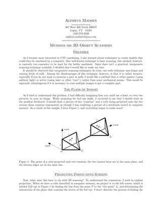
memory. As a result of this insight, I drew Figure 1, and everything began to make sense!
Figure 1: The point of a cube projected onto two cameras; the two camera faces are in the same plane, and
the bottom edges are in the same line.
Projecting Points onto Screens
Now, what does this have to do with 3D scanning? To understand the connection, I need to explain
projection. When we have a cube described in computer memory, we project it to the left screen, which is
labeled Left eye in Figure 1 by finding the line from the point P to the “eye point” Il , and determining the
intersection of the plane that contains the screen of the left eye. I won’t describe the process of finding the
2. intersection here, but finding the equation of a line in 3D space (which I’ll affectionately call R3 )is very
similar to finding the equation of a line in a plane, as you would do in high school algebra: you need to find
a slope and a starting point.
The slope is relatively easy to find, except that in R3 we have a vector direction rather than a single
number. This slope is given by
P − Il ,
since the subtraction of two points in R3 gives us the direction vector from Il to P . If we were to reverse
the subtraction, we would get a vector in the opposite direction; since this vector would be on the same line
anyway, it doesn’t really matter which order we choose.
Since we’re doing a projection, the natural choice for a starting point would be the eye point Il . Thus,
the line we would use for projection onto the left eye screen would be
Xl = (P − Il )t + Il ;
where t is any real number1 . The point where this line intersects the left eye screen would be Pl .
In a similar way, we could find another line to project P to Pr for the other eye point Ir .
If we wanted to scan a picture using binocular vision, we would repeat this process. Instead of using P
to find Pl and Pr
Reversing the Projection
When I first attempted to understand laser scanning, and later binocular vision, I had difficulty under-
standing how knowing the laser-beam line L and Pl , or alternately, knowing Pl and Pr , would be useful for
finding the point P . The answer turns out to be surprisingly simple: we reverse the process of projection!
The point P is simply the intersection of two lines. In laser scanning, the first line would be given by
Xl = (Pl − Il ) + Il ;
and the second line would be L if we are using laser scanning, or
Xr = (Pr − Ir ) + Ir
if we are using a pair of cameras.
Why didn’t I understand this initially? It turns out that the descriptions I saw, first for laser scanning,
and later for binocular vision, left out an important piece of information: the “eye point” of the camera! For
computer graphics, the eye point represents where you, as the computer programmer, expect the viewer to
be, when looking at the computer screen2 . For a literal camera, however, the eye point is the focal point of
the lens that projects the real-world image onto its film mechanism.
In other words, it isn’t enough to just know L and Pl , or Pl and Pr . We need more information to
determine where a point is in R3 !
A Few Observations on Camera Calculations
Once we identify Pl and Pr , deciding where they are in R3 is pleasantly simple. We simply identify the
lower left-hand corner of the left eye as the origin O, the x-axis to be in the direction of the left-hand side of
the left eye screen, the y-axis to be in the direction of the bottom edge of the left eye screen, and the z-axis
to be perpendicular to these other two axes. See Figure 2 to see what this R3 coordinate frame would look
like. Note that, in this figure, n represents the distance between the two camera systems.
In this system, points Pl and Pr would be vectors of the form
Pl = (xl , yl , 0)
and
Pr = (xr , y + n + yr , 0),
1 If we choose t to be between 0 and 1, then this would even represent the line segment from Il to P shown in the picture.
2I have attempted to experiment with various eye points, but the mathematics of non-centered eye points get rather com-
plicated, and I haven’t yet had the time to get the projections right.
3. Figure 2: A convenient coordinate frame for two cameras used in binocular vision. Note that the right eye
camera could be replaced with a laser, a laser-generated line, or even a laser-generated grid.
where y is the length of the bottom of each camera. If we move the camera to a different position, we can
then transform this local coordinate system to the “fixed” system of the part we are attempting to scan; this
will be necessary for objects that require more than one scanning position to get the complete information
of the object. All but the simplest objects will require this!
Of course, all this seems simple until we ask ourselves: how do we identify Pr with Pl ? If we are using
a laser, we simply find the dot, or line, or grid, of the right color. For binocular vision, however, the answer
isn’t so straightforward, especially since projection distorts figures somewhat! Points farther away from the
camera are closer to each other than points close up. I am not aware of any algorithms used to answer this
question, but personally, I would attempt to use the following procedure:
1. I would consider using a precision “coordinate frame” in each picture to create a frame of reference (a
precision-made cube of known size would be sufficient).
2. Then, I would use color to determine the “border structure” of the two pictures. I would assume that
any place where the color changes “continuously” would be a flat, or at least a “smooth”, surface, and
that any sudden “jumps” would indicate a sharp edge of some sort. “continuous” and color “jumps”
would be somewhat subjective, since computer pixels are discrete units rather than strictly continuous.
3. Next, I would then try to match the two border structures to each other using algebraic topology and
other topological techniques. Topology is a “primitive” geometry where distortions don’t matter; thus,
it would be ideal for this technique.
4. Finally, I would match the points in the “interior” of the border structure, and reverse the projection
on each point; alternately, I would simply reverse the projection of the border structure itself, and
attempt to use the rate of change of colors and shading to obtain even more depth information.
It should also be observed also that certain aspects of the hardware used should also need to be taken
into consideration, to achieve the level of precision required. For example:
1. Camera pixel size needs to be taken into consideration; additionally, the finer the resolution of the
camera, the more accurate the information will be.
2. To simplify things, the two cameras should be as identical to each other as possible. It would be nice if
the two cameras could be controlled by software! It would also be nice if the cameras could be removed
from the system for day-to-day use.
3. The two cameras (or the camera and laser) would need to be placed with high precision; tests would
have to be devised to determine the precision.
4. The focal points of the cameras would also have to be determined with high precision. If the two
cameras are made specifically for this purpose, then it would be up to me to accurately place the lens;
if I chose to use two commercial cameras, then it might be more challenging to get this information.
4. 5. Since I am interested in making a system that is affordable for hobbyists, I would probably make the
software available for this “open-source”, and I would want to use commercial cameras; thus, I would
also have to develop routines for calibration.
6. The cameras should be mounted to a computer controlled arm-system that could move the cameras
into all sorts of positions. The blueprints of this should be made available to anyone who would like
to duplicate it; I would imagine that, if I had the shop to produce this, that I could sell kits (or even
complete systems) to those who didn’t have a shop to produce this, but wanted to scan things.