1. 2/19/2014
application_architecture3.html
Welcome venkateswarlu
Account Sign Out Help Country
Products
Oracle Technology Network
Articles
Solutions
Communities
Downloads
I am a...
Store
I want to...
Support
Training
Search
Partners
About
OTN
Enterprise Architecture
Application Development
Framew ork
Application Architecture for Applications Built on BEA WebLogic Platform 8.1
Pages: 1, 2, 3
Application Express
Physical View
Big Data
Business Intelligence
Cloud Computing
Communications
The Physical View (aka Deployment View) shows the hardware upon which the application will be deployed. It also describes which parts of the
application are deployed to which physical pieces of hardware.
The hardware and software deployment described in this section is an example of how an application built on the WebLogic Platform can be
deployed and represents the "most common" or "best practice" architecture. However, there are many possible alternate configurations; the
actual hardware architecture will depend on the actual application and balances a multitude of often conflicting constraints including budget,
reliability, availability, scalability, security, and preexisting network and computing resources.
Database Performance &
Availability
Hardware Deployment
Data Warehousing
Figure 2 illustrates a typical hardware environment onto which an application built on the WebLogic Platform could be deployed.
.NET
Dynamic Scripting Languages
Embedded
Digital Experience
Enterprise Architecture
Enterprise Management
Identity & Security
Java
Linux
Service-Oriented Architecture
Solaris
SQL & PL/SQL
Systems - All Articles
Virtualization
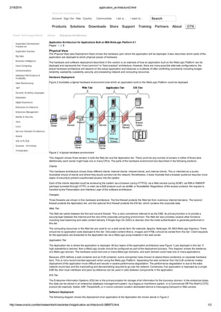
Figure 2. A typical hardware environment
This diagram shows three servers in both the Web tier and the Application tier. There could be any number of servers in either of those tiers.
Additionally, each server might have one or many CPUs. The parts of the hardware environment are described in the following sections.
Clients
This hardware architecture shows three different clients: Internet clients, intranet clients, and internal clients. This is intended as a purely
illustrative choice of clients and where they would connect into the network. Nonetheless, it does illustrate that a broader audience requires more
layers of security to prevent unauthorized access into the system.
Each of the clients depicted could be accessing the system via a browser (using HTTP(S), via a Web service (using SOAP), via RMI or RMI/IIOP
(perhaps tunneled through HTTP), or even via a B2B protocol such as ebXML or RosettaNet. Regardless of the access protocol, the request is
handled by the Presentation and Interface Layer of the software architecture.
Firewalls
Three firewalls are shown in this hardware architecture. The first firewall protects the Web tier from malicious Internet denizens. The second
firewall protects the Application tier, and the optional third firewall protects the EIS tier, which contains the corporate data.
Web Tier
The Web tier exists between the first and second firewall. This is also sometimes referred to as the DMZ. Its primary function is to provide a
security layer between the Internet and the rest of the corporate computing environment. The Web tier also provides several other functions
including load balancing and static content delivery. If Single-Sign-On (SSO) is desired, then the initial authentication is generally performed in
this tier.
The computing resources in the Web tier are used to run a web server farm (for example, Apache, Netscape, IIS, BEA WebLogic Express). There
should be no application code deployed to this tier. Only static content (that is, images and HTML) should be served from this tier. Client requests
for the application are forwarded to the Application tier via a WebLogic proxy installed in the web server.
Application Tier
The Application tier is where the application is deployed. All four layers of the application architecture (see Figure 1) are deployed in this tier. If
high availability is desired, then a WebLogic cluster should be configured as part of the deployment process. This diagram shows the existence
of a WebLogic domain. The hardware could host one or many WebLogic domains, and each domain could have one or many applications.
Because J2EE defines a web container and an EJB container, some companies have chosen to deploy these containers on separate hardware
tiers. This is not a recommended approach when using the WebLogic Platform. Separating the web container from the EJB container makes
deployment of the application more difficult and results in severe performance degradation. The performance degradation is due to the extra
network round trips and the marshalling and demarshalling required to go over the network. Conversely, if an application is deployed as a single
EAR file, then local interfaces and pass by reference can be used in calls between components in the application.
EIS Tier
The Enterprise Information Systems (EIS) tier is the primary location for storage of all information for the business domain. In the enterprise today,
this data can be stored in an enterprise database management system, by a legacy or mainframe system, in a Commercial-Off-The-Shelf (COTS)
product (for example, Siebel, SAP, PeopleSoft), or in some unknown location abstracted behind a messaging transport or Web service.
Software Deployment
The following diagram shows the deployment of an application to the Application tier shown above in Figure 2.
http://www.oracle.com/technetwork/articles/entarch/application-architecture3-086973.html
1/3
2. 2/19/2014
application_architecture3.html
Figure 3. Deployment of an application to the Application tier
This shows a single, clustered application deployed to all three servers in the Application tier. This is the simplest way to deploy an application
build on the WebLogic Platform, but there are many other possibilities. The next diagram illustrates another type of deployment:
Figure 4. Portal application and BPM
This figure shows a portal application on two servers in a cluster and a separate application for Business Process Management (BPM) deployed
to a single server. In this deployment the portal application provides high availability while the BPM application does not. Such a deployment might
be appropriate if the portal application is critical and uses a non-critical BPM application.
These examples show three servers with one WebLogic instance on each. However, there could be any number of servers and one or multiple
WebLogic instances per server. In fact, there is a tremendous amount of flexibility in the way that applications can be deployed on the BEA
WebLogic Platform. Some deployment "rules of thumb" are:
One instance of WebLogic for every two or three CPUs
Applications that are to be administered together should be in a common WebLogic domain
Applications that are unrelated should go in separate WebLogic domains even if they are sharing hardware resources
WebLogic instances should be clustered if high availability or fault tolerance is a requirement
If the application needs N servers to provide the necessary performance and throughput, then the application should be deployed on N+1 servers
to allow for server outages (either planned or unplanned).
This section concludes the discussion of hardware and software deployment in the Physical View. The next section will examine the Process
View of the 4+1 View Model.
Process View
The Process View (aka Concurrency View) shows the various processes and the communication that occurs between the processes. The
following diagram illustrates the processes that are involved in servicing a web browser request for data that resides in a relational database.
Figure 5. Process View
This simple example of a process diagram shows that multiple processes and threads are involved in servicing a single browser request. The
process diagram could be much more complex especially if asynchrony and multiple back end systems are involved in servicing a single request.
The next diagram illustrates the processes and threads of the WebLogic Platform.
Figure 6. Processes and threads of the Web Logic Platform
As illustrated in the above diagram, a single instance of WebLogic Server corresponds to a single process with multiple threads. By default,
WebLogic Server is configured with a single request queue. Additional request queues can be configured to separate different types of requests.
For example, it might be desirable to separate higher priority requests from low priority computationally expensive requests.
http://www.oracle.com/technetwork/articles/entarch/application-architecture3-086973.html
2/3
3. 2/19/2014
application_architecture3.html
When using the pure-Java socket reader implementation, the Socket Reader threads and Worker threads both come from the same thread pool.
When native IO is configured, the native socket reader multiplexor threads have their own execute queue and do not borrow threads from the
request queue thread pool.
Communication
By and large, the communication within an application built on the WebLogic Platform is handled transparently by the platform. However, there are
some communication constructs supported by the platform that may have important architectural impacts.
Conversations
The Web services provided by the WebLogic Platform provide a mechanism to easily create a conversation between the client and the application.
The state of the conversation is stored persistently so the conversation can be long lived and can survive even a complete system shutdown.
(Conversation timeouts can also be set so that abandoned conversations are cleaned up automatically.)
Asynchronous Support
The WebLogic Platform provides several mechanisms for asynchronous communication.
The control architecture provides a simple mechanism to create and register for callbacks.
An asynchronous web service can be easily constructed with a Java Web Service (JWS) file.
The platform includes a reliable SOAP messaging framework whereby an application running in one WebLogic instance can asynchronously and
reliably invoke a web service running on another WebLogic instance.
The platform includes a message broker that allows asynchronous communication to and from Process Definitions.
The platform includes JMS and MDB support, which are the J2EE standard mechanisms for asynchronous communication.
Security
Security is not generally thought of as part of the communication between components within an application. However, WebLogic Platform
includes an industry-leading security infrastructure that is transparently intercepting and taking action on communications within the application.
This security infrastructure is part of WebLogic Server and is leveraged by the rest of the platform to create consistent, declarative, policy-based
security for all aspects of the application. The need to write custom code to enforce security within the application should be very rare.
The WebLogic Platform also supports WS-Security. This not only provides encryption of web services messages but also ties the web services
stack into the underlying security infrastructure.
WebLogic Enterprise Security (WLES) is another BEA product that can be incorporated into a solution built on the WebLogic Platform. WLES
provides enhanced application security that includes: policy-based delegated administration, authentication with single sign-on, consolidated
auditing, and dynamic-role and policy-based authorization with delegation.
Conclusion
The goal of this article is to present the extensive functionality provided by the BEA WebLogic Platform in a high-level view easily digestible by
application architects and designers. To accomplish this, the 4+1 View Model was used to describe the architecture of applications built on the
WebLogic Platform. The Developer View provides a unified view of the components provided by WebLogic Server, WebLogic Portal, WebLogic
Integration, WebLogic Workshop, and Liquid Data for WebLogic. This view also shows the architectural layers in a well-designed application and
identifies the components used in each of the layers. The Physical View provides a simple example of a deployment of an application built on the
WebLogic Platform. Both the software deployment and the physical hardware deployment are depicted. The Process View describes the threads
and processes involved in servicing a user request. It also touches on application communication issues such as conversations, asynchrony,
and security.
We hope that this furnishes a better understanding of the WebLogic Platform and the robust foundation that it provides for application
development and that this understanding can be used to help build and design applications that leverage the capabilities provided by the
WebLogic Platform.
Additional Reading
Introduction to OMG's Unified Modeling Language (UML)
Object Oriented Analysis
Architectural Blueprints - The "4+1" View Model of Software Architecture (PDF)
Bob Hensle has over 20 years of industry experience including more than eight years with BEA Consulting.
E-mail this page
ORACLE CLOUD
Learn About Oracle Cloud
Get a Free Trial
Learn About PaaS
Learn About SaaS
Learn About IaaS
JAVA
Learn About Java
Download Java for
Consumers
CUSTOMERS AND EVENTS
Explore and Read Customer
Stories
All Oracle Events
Download Java for Developers
Java Resources for
Developers
Java Cloud Service
Java Magazine
Oracle OpenWorld
JavaOne
COMMUNITIES
Blogs
Discussion Forums
SERVICES AND STORE
Log In to My Oracle Support
Training and Certification
Wikis
Oracle ACEs
User Groups
Social Media Channels
Printer View
Become a Partner
Find a Partner Solution
Purchase from the Oracle
Store
CONTACT AND CHAT
Phone: +1.800.633.0738
Global Contacts
Oracle Support
Partner Support
Subscribe Careers Contact Us Site Maps Legal Notices Terms of Use Privacy Cookie Preferences Oracle Mobile
http://www.oracle.com/technetwork/articles/entarch/application-architecture3-086973.html
3/3