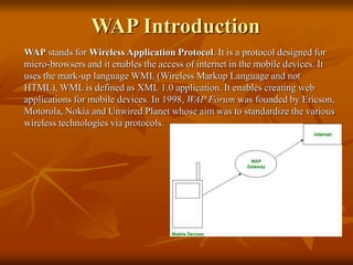
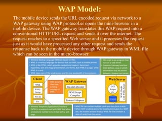
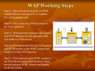
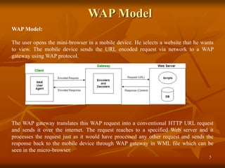
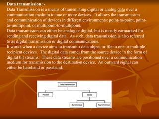
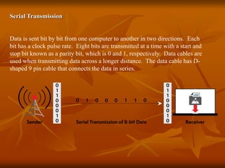
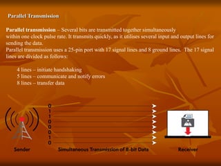
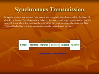
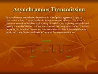
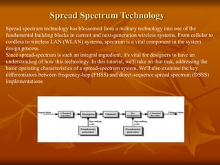
1. WAP (Wireless Application
Protocol)
Prof. Neeraj Bhargava
Shweta Sharma
Department of Computer Science
School of Engineering and System
Sciences,
MDS University, Ajmer
2. WAP Introduction
WAP stands for Wireless Application Protocol. It is a protocol designed for
micro-browsers and it enables the access of internet in the mobile devices. It
uses the mark-up language WML (Wireless Markup Language and not
HTML), WML is defined as XML 1.0 application. It enables creating web
applications for mobile devices. In 1998, WAP Forum was founded by Ericson,
Motorola, Nokia and Unwired Planet whose aim was to standardize the various
wireless technologies via protocols.
3. WAP Model:
The mobile device sends the URL encoded request via network to a
WAP gateway using WAP protocol.er opens the mini-browser in a
mobile device. The WAP gateway translates this WAP request into a
conventional HTTP URL request and sends it over the internet. The
request reaches to a specified Web server and it processes the request
just as it would have processed any other request and sends the
response back to the mobile device through WAP gateway in WML file
which can be seen in the micro-browser.
4. WAP Working Steps
4
Step 1:- Open the micro browser on WAP
enabled devices and type Url of website.
Ex:- www.google.com
Step 2:- Url is sent using WAP protocol to
the WAP gateway.
Step 3:- WAP gateway translates this request
into HTTP Request for the specified URL
and sends it to Web server.
Step 4:- Web Server process the Url Request,
add HTTP header to the WML content and
returns in to the WAP gateway.
Step 5:- WAP gateway send WML content to
the WAP device using WAP protocol, micro
browser process WML content and display
on device screen.
5. WAP Model
5
WAP Model:
The user opens the mini-browser in a mobile device. He selects a website that he wants
to view. The mobile device sends the URL encoded request via network to a WAP
gateway using WAP protocol.
The WAP gateway translates this WAP request into a conventional HTTP URL request
and sends it over the internet. The request reaches to a specified Web server and it
processes the request just as it would have processed any other request and sends the
response back to the mobile device through WAP gateway in WML file which can be
seen in the micro-browser.
7. WAP Protocol Stack
Application Layer:
This layer contains the Wireless Application Environment (WAE). It contains
mobile device specifications and content development programming languages
like WML.
Session Layer:
This layer contains Wireless Session Protocol (WSP). It provides fast
connection suspension and reconnection.
Transaction Layer:
This layer contains Wireless Transaction Protocol (WTP). It runs on top of
UDP (User Datagram Protocol) and is a part of TCP/IP and offers transaction
support.
Security Layer:
This layer contains Wireless Transaction Layer Security (WTLS). It offers data
integrity, privacy and authentication.
Transport Layer:
This layer contains Wireless Datagram Protocol. It presents consistent data
format to higher layers of WAP protocol stack.
8. Data transmission :-
Data Transmission is a means of transmitting digital or analog data over a
communication medium to one or more devices. It allows the transmission
and communication of devices in different environments: point-to-point, point-
to-multipoint, or multipoint-to-multipoint.
Data transmission can either be analog or digital, but is mostly earmarked for
sending and receiving digital data. As such, data transmission is also referred
to as digital transmission or digital communications.
It works when a device aims to transmit a data object or file to one or multiple
recipient devices. The digital data comes from the source device in the form of
digital bit streams. These data streams are positioned over a communication
medium for transmission to the destination device. An outward signal can
either be baseband or passband.
9. Serial Transmission
Data is sent bit by bit from one computer to another in two directions. Each
bit has a clock pulse rate. Eight bits are transmitted at a time with a start and
stop bit known as a parity bit, which is 0 and 1, respectively. Data cables are
used when transmitting data across a longer distance. The data cable has D-
shaped 9 pin cable that connects the data in series.
10. Parallel Transmission
Parallel transmission – Several bits are transmitted together simultaneously
within one clock pulse rate. It transmits quickly, as it utilises several input and output lines for
sending the data.
Parallel transmission uses a 25-pin port with 17 signal lines and 8 ground lines. The 17 signal
lines are divided as follows:
4 lines – initiate handshaking
5 lines – communicate and notify errors
8 lines – transfer data
11. Synchronous Transmission
In synchronous transmission, data moves in a complete paired approach in the form of
chunks or frames. Synchronisation between the source and target is required so that the
source knows where the new byte begins, since there are no spaces between the data.
This method offers real-time communication between linked devices.
12. Asynchronous Transmission
In asynchronous transmission data moves in a half-paired approach, 1 byte or 1
character at a time. It sends the data in a constant current of bytes. The size of a
character transmitted is 8 bits, with a parity bit added at the beginning and at the end,
making it a total of 10 bits. It doesn’t need a clock for integration—rather, it utilises
the parity bits to inform the receiver how to translate the data. It is straightforward,
quick, and cost-effective, and it doesn’t require 2-way communication.
13. Difference B/W Synchronous and
Asynchronous
Synchronous Asynchronous
1. Synchronous transmission is fast.
2. Synchronous transmission is costly
3. In Synchronous transmission, time
interval of transmission is constant.
4. In Synchronous transmission, There
is no gap present between data.
5. Efficient use of transmission line is
done in synchronous transmission.
6. Synchronous transmission needs
precisely synchronized clocks for
the information of new bytes
1. Asynchronous transmission is slow.
2. Asynchronous transmission is economical.
3. In asynchronous transmission, time interval
of transmission is not constant, it is random.
4. In asynchronous transmission, There is
present gap between data.
5. While in asynchronous transmission,
transmission line remains empty during gap
in character transmission.
6. Asynchronous transmission have no need of
synchronized clocks as parity bit is used in
this transmission for information of new
bytes.
14. Multiplexing
Multiplexing is a technique used to combine and send the multiple data streams over a
single medium. The process of combining the data streams is known as multiplexing and
hardware used for multiplexing is known as a multiplexer.
Multiplexing is achieved by using a device called Multiplexer (MUX) that combines n
input lines to generate a single output line. Multiplexing follows many-to-one, i.e., n input
lines and one output line.
16. FDMA (Frequency Division Multiple Access
Frequency Division Multiplexing (FDM) is a networking technique in which multiple data
signals are combined for simultaneous transmission via a shared communication medium.
FDM uses a carrier signal at a discrete frequency for each data stream and then combines
many modulated signals.
When FDM is used to allow multiple users to share a single physical communications
medium (i.e. not broadcast through the air), the technology is called frequency-division
multiple access (FDMA).
F1 F2 F3
User1 User 2 User 3
17. TDMA (Time Division Multiple Access)
Time Division Multiple Access (TDMA) : a digital wireless telephony transmission
technique. TDMA allocates each user a different time slot on a given frequency. TDMA
divides each cellular channel into three time slots in order to increase the amount of data that
can be carried.
Time Division Multiple Access (TDMA) is a complex technology, because it requires an
accurate synchronization between the transmitter and the receiver. TDMA is used in digital
mobile radio systems. The individual mobile stations cyclically assign a frequency for the
exclusive use of a time interval.
In most of the cases, the entire system bandwidth for an interval of time is not assigned to a
station. However, the frequency of the system is divided into sub-bands, and TDMA is used
for the multiple access in each sub-band. Sub-bands are known as carrier frequencies. The
mobile system that uses this technique is referred as the multi-carrier systems.
18. Spread Spectrum Technology
Spread spectrum technology has blossomed from a military technology into one of the
fundamental building blocks in current and next-generation wireless systems. From cellular to
cordless to wireless LAN (WLAN) systems, spectrum is a vital component in the system
design process.
Since spread-spectrum is such an integral ingredient, it's vital for designers to have an
understanding of how this technology. In this tutorial, we'll take on that task, addressing the
basic operating characteristics of a spread-spectrum system. We'll also examine the key
differentiators between frequency-hop (FHSS) and direct-sequence spread spectrum (DSSS)
implementations.
20. FHSS (Frequency Hopping Spread Spectrum)
Frequency Hopping Spread Spectrum (FHSS)
Why to use :-
• Interference
• Spying
The Frequency Hopping Spread Spectrum or FHSS allows us to utilize bandwidth properly
and maximum. In this technique, the whole available bandwidth is divided into many
channels and spread between channels, arranged continuously.
The frequency slots are selected randomly, and frequency signals are transmitted according
to their occupancy.
The transmitters and receivers keep on hopping on channels available for a particular
amount of time in milliseconds.
21. Types Of FHSS
Slow Hopping: In slow hopping, multiple bits are transmitted on a specific frequency or
same frequency.
Fast Hopping: In fast hopping, individual bits are split and then transmitted on different
frequencies.
22. DSSS (Direct Sequence Spread Spectrum)
The Direct Sequence Spread Spectrum (DSSS) is a spread-spectrum modulation technique
primarily used to reduce overall signal interference in telecommunication. The Direct
Sequence Spread Spectrum modulation makes the transmitted signal wider in bandwidth than
the information bandwidth. In DSSS, the message bits are modulated by a bit sequencing
process known as a spreading sequence. This spreading-sequence bit is known as a chip. It
has a much shorter duration (larger bandwidth) than the original message bits. Following are
the features of Direct Sequence Spread Spectrum or DSSS.
• In Direct Sequence Spread Spectrum or DSSS technique, the data that needs to be
transmitted is split into smaller blocks.
• After that, each data block is attached with a high data rate bit sequence and is transmitted
from the sender end to the receiver end.
• Data blocks are recombined again to generate the original data at the receiver's end, which
was sent by the sender, with the help of the data rate bit sequence.
• If somehow data is lost, then data blocks can also be recovered with those data rate bits.
• The main advantage of splitting the data into smaller blocks is that it reduces the noise and
unintentional inference.
23. DSSS (Direct Sequence Spread Spectrum)
• Spreading code:- 100001
• 0 is always written = -1
0 = -1
• After modification your code is :- (1,-1,-1,-1,-1,1)
• Data code is :1, -1, 1, -1 , 1, -1