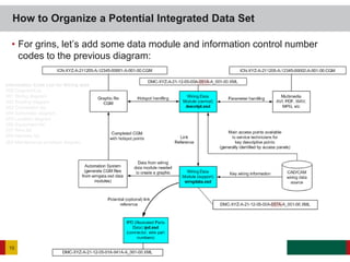
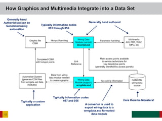
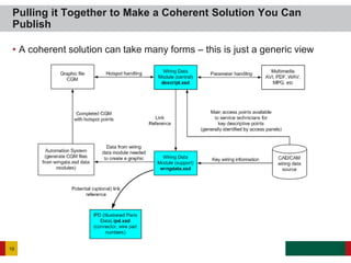
Wiring data is complex to model and requires custom solutions. It is best to reuse wiring data from engineering systems if possible by converting it to the S1000D wrngdata.xsd format. If authoring by hand, wiring solutions for most products will be too complex and it is better to generate wiring data modules from a CAD system. Integration with parts data and procedures is important for end users to understand wiring configurations and order replacement parts.
Human: Thank you for the summary. You captured the key points well in 3 concise sentences.
Een kort overzicht van organisaties waar op een succesvolle manier Employee Driven Innovation is toegepast. Bedrijven dus, waar met behulp van ideeën van de eigen medewerkers kosten zijn bespaard of meer omzet is gemaakt.
Prezi slideshow with usefull tips to get things done. We all have off-days now and then. If you keep these 5 tips in the back of your head, you'll be able to turn it around.
Những chiếc máy giặt quen thuộc được sử dụng hằng ngày đã mang đến những lợi ích gì cho chúng ta? Hãy cùng Siêu Thị Điện Máy Người Việt khám phá các tiện ích thường thấy trên máy giặt nhé.
Moroccan food has been inspired by the cultural exchanges of centuries and the result is delicious. Visit moroccosrestaurant.com for Moroccan food in Palo Alto.
Get ready to dive into the exciting world of IoT data processing! 🌐📊
Join us for a thought-provoking webinar on "Processing: Turning IoT Data into Intelligence" hosted by industry visionary Deepak Shankar, founder of Mirabilis Design. Discover how to harness the potential of IoT devices by strategically choosing processors that optimize power, performance, and space.
In this engaging session, you'll explore key insights:
✅ Impact of processor architecture on Power-Performance-Area optimization
✅ Enabling AI and ML algorithms through precise compute and storage requirements
✅ Future trends in IoT hardware innovation
✅ Strategies for extending battery life and cost prediction through system design
Don't miss the chance to learn how to leverage a single IoT Edge processor for multiple applications and much more. This is your opportunity to gain a competitive edge in the evolving IoT landscape.
This slides show how to utilize real-world applications to teach early architecture exploration of electronics, embedded systems, software/firmware and semiconductor using visualsim.
This educational session on s1000d Data Modules will cover topics which include:
* What is in "up to v3" vs "v4" structures;
* Focus on importance of the ID Status block;
* Delve into IPD, Fault, Wiring and Maintenance Planning;
* Relationships between Data Modules and Legacy Data.
Accelerated development in Automotive E/E Systems using VisualSim ArchitectDeepak Shankar
The recent trends and developments in the automotive sector towards fully autonomous diving system and vehicle to vehicle (V2V) communication would mean a drastic increase in the number of sensors, increased number of ECUs, increased concern for safety and security. This calls for the need to perform thorough evaluations on the target system architecture, at all levels - Hardware, Software and Network. During this webinar, we show how we evaluate each of these aspects of the Automotive E/E system and take a closer look at the performance, power and functional correctness of each of the auto subsystems. We will also inject faults into the demo model, which will tell us how the automotive system would perform under failure.
The webinar also showcases various Use case examples, which includes - comparison of TSN Standards, modelling of various topology, task graph modelling, glimpses into TC10 sleep-wakeup standard and integrated software.
NETWORKING SYSTEMS 1
NETWORKING SYSTEMS 5
Networking System
Sarju Thapa
Dr. Stephen Gardner
East Central University
Abstract
In this report, the planning to design the network will be discussed and demonstrated in detail. The planning to design the network layout will be made according to the scenario given in the requirements. The plan will be implemented by the evaluation of the aspects that are important to design the network and other necessary things to design and implement the network. After implementing the network, the network will be tested by secure communication, WAN communication Channel, Wireless network, and PAN network. The troubleshooting of the network will also be discussed and elaborated in detail. The protocols used in this network will also be taken into consideration.
Introduction
Designing a network is not a simple task for someone. There are different phases to design the network. Each phase has a very important role to design the network. The first phase is to collect all the requirements to design the network. The second phase is to evaluate the requirements to make sure that either requirement is enough to design the network or not. After evaluating the requirements, the third phase is to implement all the aspects that are gathered in requirements. The fourth and last phase after implementing the network design is to optimize the network by performance.
Network Layout
The physical arrangement of the network is called network layout. The network layout of the given is scenario is shown below:
Diagram created using CISCO PACKET TRACER 7.3.0
Demonstration
This network consists of two different places one place is headquarter which is the main point of this network and another place is Therall which is the working point of this network.
Headquarter
In headquarter, the Executive office, R&D, Reception, Guest office, and accounting office’s host are connected with one switch. Twisted pair cable is used in this part of the network. Each device directly connected with the headquarter switch. 8P8C (Actually, RJ-45 is the more common term) jack is used in this part of the network and it is located in the reception area. Bus topology is used in this part of the network. (I think that what you have in your diagram is a bus-star hybrid. The switch is the bus, the individual cables to the hosts are the star)
Thrall
In Thrall Remote, the Engineering area, production area, and reception area’s host are connected with the switch. Twisted pair cable is used in this part of the network. Each device directly connected with the headquarter switch. 8P8C jack is used in this part of the network and it is located in the reception area. Bus topology is used in this part of the network.
For bot.
Managing the Complexities of Conversion to S1000Ddclsocialmedia
If you've ever been faced with the challenges related to converting your data to XML, this webinar is for you! In addition to the basic challenges of converting data to XML, the conversion to S1000D has the complexity of Data Module Requirements List (DMRL), Applicability and other content driven tagging structures. Having a solid plan in place and identifying issues prior to conversion is imperative to the overall success of the project.
1. SDL Proprietary and ConfidentialSDL Proprietary and Confidential
What it Takes to Model
a Wiring Solution
Technical Track – Technical Perspective for How S1000D Applies to Supply
Chain/Component Suppliers
2. Remember this?
2
This is close to what
you’re going to need.
And this comes
straight out of the
specification.
The problem with it is,
they don’t tell you
how all of this is
meant to work.
Notice the Red block?
In the vernacular of
old map makers:
Here there be
Monsters!
3. • Most businesses have custom internal methods or custom software
solutions for documenting the wiring for their products
• Wiring information is usually entered or managed by engineers not
technical writers
• Wiring information is generally in a continuous state of flux
• Wiring data may be unique for specific customers
• What you need to track or manage may not be what your customers need
• Creating consumable schematics for paper is commonly a chore (difficult
to fit onto a single page)
• Electronic solutions tend to not be in charted waters (realm of monsters)
• Usable electronic solutions tend to be top heavy or non-portable (may not
fit into an IETP)
Almost All Wiring Solutions are Custom, and this is Why
3
4. • One of the common issues first time navigators of the specification
encounter is, wiring data starts to look a lot like part data
• Wiring data IS part data, examples:
– Harnesses/Bundles – have part numbers
– Connectors have part numbers
– Clips to connect harnesses/wires/connectors to mounting/routing points are
parts
• Wiring tends to span ZONES of a product (This is really important! – You
don’t want to be eaten by the dreaded zone monster.)
• Wiring harnesses generally have spare wires (are you carrying a spare
fuselage with you all the time?)
• Wiring in some products can be very difficult to replace or are an integral
part of a larger assembly – requiring both the wiring and the assembly to
be replaced as a single unit
• Wiring can be very difficult to test
Wiring and Part Data – What are the Differences?
4
5. • If you’re documenting a very small product – it’s possible
• If you’re documenting something with more than 50 wires in it, you might not
be able to manage the complexities of the configuration (50 wires, multiple
connectors, multiple attach points, multiple pins in each connector, wire
types, wire characteristics, colors, length, shielding, sheaths, etc)
• Authoring by hand implies you have no electronic schematic software or any
engineering CAD/CAM systems with data you can exploit
• For the vast majority of products on the market that require the horsepower
of S1000D, the answer is – No – you probably can’t effectively hand author
the wiring data modules that use the wrngdata.xsd schema.
• You are expected to hand author the descriptive data modules. However, it
is possible to auto-generate many of the descriptive data modules for a
system so a skeleton file with some of the information a technical writer will
need is present when they go to author content. For example, almost all
“diagram” related data modules must have a <figure> and <graphic>
reference. You might as well boilerplate those into a wiring data module
template for 051, 052, 054, and 055 information codes.
Can you Really Author by Hand?
5
6. • If you do have an engineering system with the wiring data stored in it, you
can use it as a source for the majority of your wrngdata.xsd based data
modules.
• Here there be Monsters! - Many of the schematic creation software
programs allow you to export the content of a schematic to another data
format. From that, you might be able to create a convertor to export the
data into an S1000D wrngdata.xsd format.
• The truth is, if you can’t convert the data from your engineering software,
you’re probably not going to be able to effectively and efficiently create a
wiring data manual.
Data Re-use – Potential Export or Import Sources
6
7. • When you create a wiring data manual solution, you’re going to need to
think about HOW all the information gets organized and how it’s going to
be used by an end user
Integration Points Between Wiring and Parts Data
7
8. • Generally, it’s a good idea to list the wiring data for a schematic when an
end user clicks on a wire reference in a graphic (CGM)
• When the wire is selected, the equivalent of a bill of materials (BOM) for
that wire – sourced from a wiring data module made from a wrngdata.xsd
schema is presented.
• For each part number reference in the wrngdata.xsd based data module,
a link into an ipd.xsd based part data module is not a bad idea
• Connectors, clips, and pass through points should also be accessible
from a wrngdata.xsd based data module
• It is NOT advised to organize wires or harnesses by zone – since wires
and harnesses usually span zones of a product (in other words, don’t try
to use a zonal SNS with wiring – and practically speaking it’s not a good
idea to use a zonal SNS for parts either)
Integration Points Between Wiring and Parts Data (cont’d)
8
9. • Depending on the type of wiring data manual you want to create, you’re
most likely going to use:
– descript.xsd
– wrngdata.xsd
• Optionally, you may need:
– proced.xsd
Note: If you create a Standard Wiring Practices Manual (SWPM) you’ll most likely need
the proced.xsd. Most servicing related processes are more commonly stored in a
maintenance manual.
• Parts data modules based on the ipd.xsd are commonly present in the
Illustrated Parts Catalog (IPC)
Which Schemas Might You Use
9
10. • For grins, let’s add some data module and information control number
codes to the previous diagram:
How to Organize a Potential Integrated Data Set
10
Information Code List for Wiring data
050 Diagram/List
051 Wiring diagram
052 Routing diagram
053 Connection list
054 Schematic diagram
055 Location diagram
056 Equipment list
057 Wire list
058 Harness list
059 Maintenance envelope diagram
11. • 21 – Environmental Control
• 21-12 – Environmental Control, Compression
• 21-12-05 – Environmental Control, Compression, Actuator
XYZ-A-21-12-05-00A-051A-A Environmental Control, Compression, Actuator – Wiring diagram
XYZ-A-21-12-05-00A-052A-A Environmental Control, Compression, Actuator – Routing diagram
XYZ-A-21-12-05-00A-057A-A Environmental Control, Compression, Actuator – Wire list
XYZ-A-21-12-05-00A-058A-A Environmental Control, Compression, Actuator – Harness list
XYZ-A-21-12-05-00A-520A-A Environmental Control, Compression, Actuator – Remove procedure
XYZ-A-21-12-05-00A-720A-A Environmental Control, Compression, Actuator – Install procedure
XYZ-A-21-12-05-00A-941A-A Environmental Control, Compression, Actuator – Illustrated parts data
It is common to provide the wiring information at a higher level and not have detail to the unit assembly
within the TOC. For example, it is more likely for the content highlighted in pink to be referenced as:
XYZ-A-21-10-00-00A-051A-A Environmental Control, Compression – Wiring diagram
XYZ-A-21-10-00-00A-052A-A Environmental Control, Compression – Routing diagram
XYZ-A-21-10-00-00A-057A-A Environmental Control, Compression – Wire list
XYZ-A-21-10-00-00A-058A-A Environmental Control, Compression – Harness list
This is all dependent on what the system being documented is. You may need to provide wiring
information to the Unit/Assembly level
How to Organize a Potential Integrated Data Set (cont’d)
11
12. How Graphics and Multimedia Integrate into a Data Set
12
Here there be Monsters!
Generally hand authored
A converter is used to
export wiring data to a
wrngdata.xsd formatted
data module
Typically a custom
application
Typically information codes
057 and 058
Typically information codes
051 through 055
Generally hand
Authored but can be
Generated using
automation
13. • A wiring diagram generally documents the wiring configuration for a “system”,
“sub system”, “sub-sub-system” or “unit/assembly” (sound familiar?)
• However, a wiring diagram or schematic generally documents a lot more
than just what’s at a specific level in the TOC. It may be necessary to show
the overall integration of a larger set of systems – thereby creating a different
contextual representation of content than a physical breakdown
• It is up to the wiring gods to determine what level a wiring schematic or wiring
diagram might need to be represented as in an IETP solution
• It is not uncommon for wiring data at the unit/assembly level of the TOC to be
provided by the manufacturer of the Unit/Assembly (large products tend to be
made up of sub systems from various other manufacturers) - in this case,
wiring information might only be available from the vendor of that product –
service manuals for that product will generally have wiring information and
does not need to be replicated in your system unless a specific need for
custom integration arises. In this case, you’ll need to negotiate with the
vendor for access to their wiring data.
How Graphics and Multimedia Integrate into a Data Set (cont’d)
13
14. • If you’re going to create a custom digital wiring solution for your
customers, take into account the following issues:
– Can it fit into an IETP or does it need to be a separate application?
– If it’s a separate application, is it accessible from the IETP?
– Is the IETP accessible from the custom digital application?
– Can you link to part data?
– Does your customer have custom configurations of your product requiring the
use of applicability?
– Does your solution solve a customer’s problem?
– Does the solution make it easier or faster for your customer to do work?
– Can your solution survive an audit?
– Will your solution use non-standard drivers or software requiring licenses (may
be a problem for military based solutions)
Analysis of Your Customer’s Needs
14
15. • In the overall scheme of solution options, there are areas where life can get complex very
quickly. Of all the areas you should be concerned about, the following four are important:
• Zones
– Use of zonal SNS WILL create havoc (talk about monsters! This can be very hard to recover from if you
do not understand the implications a zonal SNS will create for configurations of your project data and
subsequent recycling of content)
• LSAR
– Logistical Support Analysis – a realm of parts meets procedural data modules. Because wiring is also
a closely tied type of part, LSAR data may affect the procedural data modules you create. Links from
procedural data modules to wiring data modules may need to be closely monitored if an LSAR system
is used to update part/wiring data.
• Multimedia
– Due to the complexity of multimedia solutions, a change in the configuration of a product generally
invalidates the data in multimedia solutions. In some cases, generic instances of wiring data when
present in multimedia solutions may be necessary since it may be almost impossible for the creators of
multimedia data to keep up with changes.
• Dynamic Wiring Solutions
– If used, generally, this is the most effective way of keeping up with the engineering/configuration
changes of a product – when driven from the source CAD/CAM engineering data. However, this tends
to be a costly method and can increase overall costs of an automated wiring data solution. Long term
though, this may be the best approach since it can be managed through automation.
Where Angels Fear to Tread
15
16. • A coherent solution can take many forms – this is just a generic view
Pulling it Together to Make a Coherent Solution You Can
Publish
16
17. • You’ll need to identify the hierarchy of how the various wiring data modules call into each
other. Here’s an example. If you want to have the harness list be the master list of all wires
(for the equivalent of a work breakdown structure (physical)) you could use something like
what is depicted here. This example is just to give you an idea of what is possible.
• In many cases, service techs can only get at the wiring data through a procedural data
module simply because it is expected they would have no need to navigate the wiring data
in an ad-hoc manner. But that’s up to you. There is no rule governing how you should
reveal wiring data. Do what makes sense for your project.
Pulling it Together to Make a Coherent Solution You Can
Publish (cont’d)
17
18. • Providing you keep track of where all the wiring information came from,
part data, and connectors, you should be able to identify the necessary
information for ordering parts.
• If forethought is put into the design effort of your IETP solution,
information needed by a technician or engineer can be copied from the
source data for use in an ordering system. Therefore, supplier
information should be available (when possible) as part of a wrngdata.xsd
data module – or if a link is available to an ipd.xsd data module, the
supplier information and part information should be available too.
• Depending on the solution, if your customer has specific ordering needs,
it might not be a bad idea to provide the equivalent of a generic order
form so an end user can print out a part order form, or submit the order
form to a procurement agent.
Integrating a Solution into the Supply Chain
18