Network of Excellencein Training
Dominique Bourdet
Introduction to Well
Testing
and Interpretation
WCP1 Course
2.
2
Network of Excellencein Training
• Introduction
• Well Testing Procedures and Hardware
• Examples of Typical Flow regimes
• Conclusions
Well Testing and Interpretation
3.
3
Network of Excellencein Training
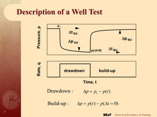
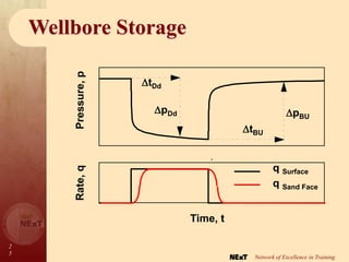
Description of a Well Test
Time, t
Rate,
q
Pressure,
p
t BU
t Dd
p Dd
p BU
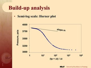
p i
p(t=0)
drawdown build-up
Drawdown :
Build-up :
p p t p t
( ) ( )
0
p p p t
i
( )
4.
4
Network of Excellencein Training
Well Test Objectives
• EXPLORATION WELL
• APPRAISAL WELL
• DEVELOPMENT WELL
5.
5
Network of Excellencein Training
Well Test Objectives
• EXPLORATION
– Nature and rate of produced fluid
– Initial pressure
– Reservoir properties
6.
6
Network of Excellencein Training
Well Test Objectives
– Reservoir properties
• permeability
• heterogeneity
• reservoir boundaries
– Well productivity
– Fluid properties (sampling)
• APPRAISAL
7.
7
Network of Excellencein Training
Well Test Objectives
– Reservoir properties
• drainage mechanism (permanent gauges)
• communication between wells
– Well productivity
– Average pressure
• DEVELOPMENT
8.
8
Network of Excellencein Training
Information obtained from Well Testing
– Reservoir responses
• Reservoir in dynamic condition (flow lines are
established)
• Large volume investigated (averaging)
p
– Results
• Permeability (horizontal k and vertical kv)
• Reservoir heterogeneities
– natural fractures,
– layering,
– change of characteristics.
• Pressure (initial pi and average )
• Boundaries (distance and shape)
• RESERVOIR DESCRIPTION
9.
9
Network of Excellencein Training
Information obtained from Well Testing
• WELL DESCRIPTION
– Results
• Production potential
– productivity index PI,
– skin factor S
• Well geometry
10.
1
0
Network of Excellencein Training
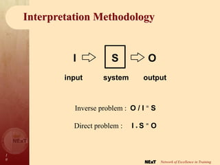
I S O
input system output
Inverse problem : O / I = S
Direct problem : I * S = O
Interpretation Methodology
11.
1
1
Network of Excellencein Training
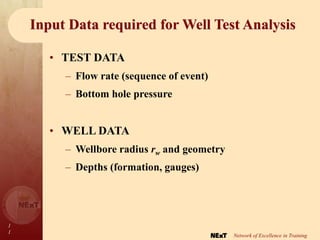
Input Data required for Well Test Analysis
• TEST DATA
– Flow rate (sequence of event)
– Bottom hole pressure
• WELL DATA
– Wellbore radius rw and geometry
– Depths (formation, gauges)
12.
1
2
Network of Excellencein Training
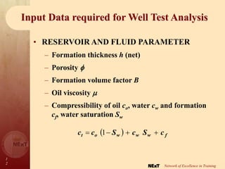
Input Data required for Well Test Analysis
• RESERVOIR AND FLUID PARAMETER
– Formation thickness h (net)
– Porosity
– Formation volume factor B
– Oil viscosity
– Compressibility of oil co, water cw and formation
cf, water saturation Sw
f
w
w
w
o
t c
S
c
S
c
c
1
13.
1
3
Network of Excellencein Training
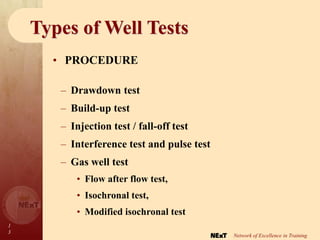
Types of Well Tests
– Drawdown test
– Build-up test
– Injection test / fall-off test
– Interference test and pulse test
– Gas well test
• Flow after flow test,
• Isochronal test,
• Modified isochronal test
• PROCEDURE
14.
1
4
Network of Excellencein Training
Types of Well Tests
• COMPLETION
– Production test
– Drill stem test (DST)
15.
1
5
Network of Excellencein Training
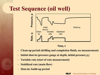
Test Sequence (oil well)
– Clean-up period (drilling and completion fluids, no measurement)
– Initial shut-in (pressure gauge at depth, initial pressure pi)
– Variable rate (start of rate measurement)
– Stabilized rate (main flow)
– Shut-in: build-up period
Time, t
Clean
up
Initial
shut-in
Variable
rate
Stabilized
rate
Build-up
Time, t
Rate,
q
Pressure,
p Clean
up
Initial
shut-in
Variable
rate
Stabilized
rate
Build-up
16.
1
6
Network of Excellencein Training
Drill Stem Test
Flowhead
BOP Stack
Casing
Tubing
Test tool
Packer
Flowhead
BOP Stack
Casing
Tubing
Test tool
Packer
• ONSHORE
TESTING
17.
1
7
Network of Excellencein Training
Drill Stem Test
• OFFSHORE TESTING
Fixed Rig (100 m maximum)
Fixed point at
Packer
Fixed Rig (100 m maximum)
Fixed point at
Packer
18.
1
8
Network of Excellencein Training
Drill Stem Test
• Cased hole
DST STRINGS
– Open hole
packer
– Barefoot
– Zonal Isolation
• Open hole
19.
1
9
Network of Excellencein Training
Surface Equipment
• FLOW HEAD: flowing, killing, wireline
• CHOKE MANIFOLD: positive & adjustable
• HEATER: hydrates, high viscosity
• SEPARATOR: metering of three phases
• TANK: oil rate
• BURNER
20.
2
0
Network of Excellencein Training
Surface Equipment
SURFACE SETUP
Burner
Burner
Heater
Separator
Surge
tank
Air
compressor
Water
pump
Rig HP
pump
Gas
Oil
Water
Choke
maniflod
Flowhead
Transfer pump
Oil
manifold
Gas
manifold
21.
2
1
Network of Excellencein Training
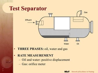
Test Separator
• RATE MEASUREMENT
– Oil and water: positive displacement
– Gas: orifice meter
Effluent
Water Oil
Gas
Effluent
Water Oil
Water Oil
Gas
• THREE PHASES: oil, water and gas
22.
2
2
Network of Excellencein Training
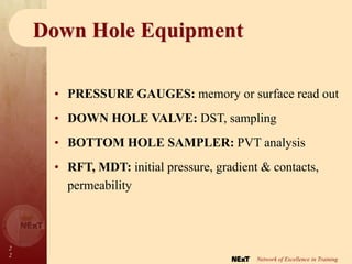
Down Hole Equipment
• PRESSURE GAUGES: memory or surface read out
• DOWN HOLE VALVE: DST, sampling
• BOTTOM HOLE SAMPLER: PVT analysis
• RFT, MDT: initial pressure, gradient & contacts,
permeability
23.
2
3
Network of Excellencein Training
Safety
• EQUIPMENT: pressure, temperature, sour gas
• PROCEDURE: pressure test, emergency shut-
down, day / night, safe area
• ENVIRONMENT: burning, oil drop out
2
5
Network of Excellencein Training
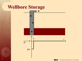
Wellbore Storage
•
Time, t
Rate,
q
Pressure,
p
q Surface
q Sand Face
tDd
pDd
tBU
pBU
26.
2
6
Network of Excellencein Training
Wellbore Storage
g
V
C u
non-eruptive well:
w
oV
c
p
V
C
C : wellbore storage coefficient
(Bbl/psi)
with
co : fluid compressibility
Vw : wellbore volume
27.
2
7
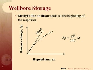
Network of Excellencein Training
Wellbore Storage
t
C
qB
p
24
• Straight line on linear scale (at the beginning of
the response)
Elapsed time, t
Pressure
change,
p
m
W
B
S
Elapsed time, t
Pressure
change,
p
m
W
B
S
28.
2
8
Network of Excellencein Training
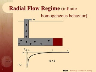
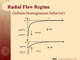
Radial Flow Regime (infinite
homogeneous behavior)
pwf
rw r
ri
p
pi
S = 0
pwf
rw r
ri
p
pi
S = 0
29.
2
9
Network of Excellencein Training
Radial Flow Regime
(infinite homogeneous behavior)
rw r
pwf(S=0)
pwf(S>0)
ri
p skin
p
pi
S > 0
rw r
pwf(S=0)
pwf(S>0)
ri
p skin
p
pi
rw r
pwf(S=0)
pwf(S>0)
ri
p skin
p
pi
S > 0
Pwf(S<0)
p skin
pi
Pwf(S=0)
S < 0
30.
3
0
Network of Excellencein Training
Radial Flow Regime
(infinite homogeneous behavior)
Skin
p
qB
kh
S
2
.
141
• SKIN:
• DAMAGED WELL (S > 0): poor contact between
the well and the reservoir (mud-cake, insufficient
perforation density, partial penetration) or invaded zone
• STIMULATED WELL (S < 0): surface of
contact between the well and the reservoir increased
(fracture, horizontal well) or stimulated zone
31.
3
1
Network of Excellencein Training
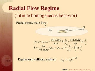
Radial Flow Regime
(infinite homogeneous behavior)
Equivalent wellbore radius: S
e
r
r w
we
w
S
w
S
S
S
w
S
w
r
r
kh
qB
r
r
h
k
qB
p
p ln
2
.
141
ln
2
.
141
0
,
,
w
S
S
S
w
S
w
r
r
k
k
p
p
qB
kh
S ln
1
2
.
141
0
,
,
Radial steady state flow:
rw
rs
ks
k
32.
3
2
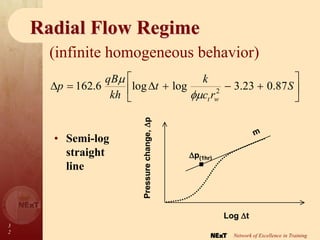
Network of Excellencein Training
Radial Flow Regime
(infinite homogeneous behavior)
S
r
c
k
t
kh
qB
p
w
t
87
.
0
23
.
3
log
log
6
.
162 2
• Semi-log
straight
line
Log t
Pressure
change,
p
m
p(1hr)
Log t
Pressure
change,
p
m
p(1hr)
33.
3
3
Network of Excellencein Training
Radial Flow Regime
(infinite homogeneous behavior)
• RESULTS:
1. the semi-log straight line slope m : the permeability k
m
qB
kh
6
.
162
23
.
3
log
151
.
1 2
hr
1
w
tr
c
k
m
p
S
2. the straight line intercept: the skin factor S
34.
3
4
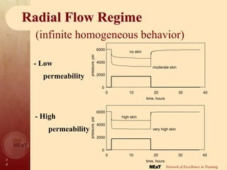
Network of Excellencein Training
Radial Flow Regime
(infinite homogeneous behavior)
- Low
permeability
- High
permeability
0
2000
4000
6000
0 10 20 30 40
time, hours
pressure,
psi
no skin
moderate skin
0
2000
4000
6000
0 10 20 30 40
time, hours
pressure,
psi
high skin
very high skin
35.
3
5
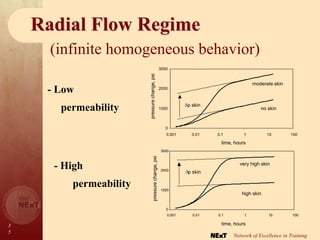
Network of Excellencein Training
Radial Flow Regime
(infinite homogeneous behavior)
- Low
permeability
0
1000
2000
3000
0.001 0.01 0.1 1 10 100
time, hours
pressure
change,
psi
no skin
moderate skin
p skin
- High
permeability
0
1000
2000
3000
0.001 0.01 0.1 1 10 100
time, hours
pressure
change,
psi
high skin
very high skin
p skin
36.
3
6
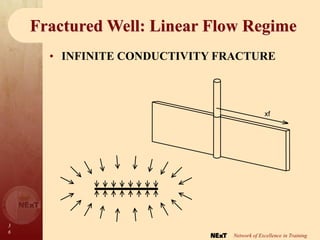
Network of Excellencein Training
Fractured Well: Linear Flow Regime
• INFINITE CONDUCTIVITY FRACTURE
xf
37.
3
7
Network of Excellencein Training
Fractured Well: Linear Flow Regime
t
k
c
hx
qB
p
t
f
06
.
4
Pressure
change,
p
m LF
t
Pressure
change,
p
m LF
t
• Straight line
with the
pressure versus
the square root
of time
38.
3
8
Network of Excellencein Training
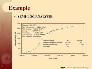
Example
• SEMI-LOG ANALYSIS
0
500
1000
1500
2000
2500
3000
1.00E-03 1.00E-02 1.00E-01 1.00E+00 1.00E+01 1.00E+02
time, hours
pressure
change,
psi
Flow rate : 1000 BOPD
Fluid Volume-Factor : 1.2000 vol/vol
Fluid Viscosity :0.500E+00 CP
porosity : 25.0000 %
net thickness : 30.000 FEET
well-bore radius :0.300E+00 FEET
Total Compres:0.185E-04 1/psi
Straight line slope : m = psi/cycle
Straight line pressure at 1 hour : Dp(1hr)= psi
Permeability thickness : kh = md.ft
Skin factor S =
39.
3
9
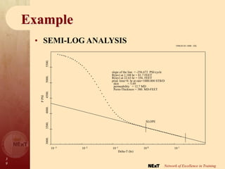
Network of Excellencein Training
• SEMI-LOG ANALYSIS
10 -3 10 -2 10 -1 10 0 10 1
3000.
3500.
4000.
4500.
5000.
5500.
Delta-T (hr)
P
PSI
SLOPE
Perm-Thickness = 380. MD-FEET
permeability = 12.7 MD
skin = 5.69
prod. time=0. hr at rate=1000.000 STB/D
R(inv) at 22.63 hr = 356. FEET
R(inv) at 1.188 hr = 81.7 FEET
slope of the line = -256.673 PSI/cycle
1996/01/01-1000 : OIL
Example
4
3
Network of Excellencein Training
Time, t
Pressure,
p
pi
p-
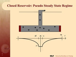
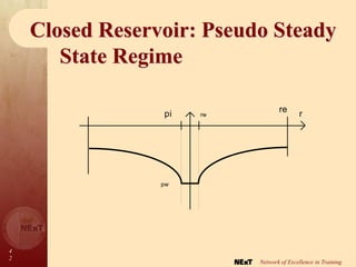
Closed Reservoir: Pseudo Steady
State Regime
• Straight line on linear scale
44.
4
4
Network of Excellencein Training
Closed Reservoir: Pseudo Steady State Regime
– At late time,
S
C
r
A
kh
qB
t
hA
c
qB
p
A
w
t
87
.
0
351
.
0
log
log
6
.
162
234
.
0 2
*
234
.
0
m
c
qB
hA
t
– Result: the reservoir pore volume
45.
4
5
Network of Excellencein Training
Well Responses
• FLOW REGIMES
– Geometry of the flow lines :
radial, linear, spherical, etc.
– Pressure : (t) =
etc.
t
t
t
1
,
,
log
– Straight line on a specialized pressure versus time plot.
46.
4
6
Network of Excellencein Training
Well Responses
• WELL RESPONSES
– Fractured well:
– Well in a channel:
1. Linear
2. Radial
1. Radial
2. Linear
4
8
Network of Excellencein Training
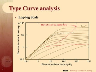
Type Curve analysis
• Log-log Scale
Dim ensionless tim e,tDCD
10-1 1 10 102 103 104
D
im
e
n
s
io
n
le
s
s
P
re
s
s
u
re
,
p
D
102
10
1
10-1
CDe2S
Start of sem i-log radial flow
49.
4
9
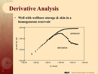
Network of Excellencein Training
Derivative Analysis
1.0E+00
1.0E+01
1.0E+02
1.0E+03
1.0E-03 1.0E-02 1.0E-01 1.0E+00 1.0E+01 1.0E+02
t, hours
p
and
p',
psi
derivative
pressure
• Well with wellbore storage & skin in a
homogeneous reservoir
50.
5
0
Network of Excellencein Training
Derivative Analysis
Dimensionless
pressure,
p
D
102
10
1
10-1
10-1
1 10 103
104
105
CD e 2S
103
3
1030
1020
1015
1010
106
104
0.3
102
Approximate
end of
wellbore
storage
DAMAGED
NORMAL
ACIDIZED
1040
1050
1060
108
10
1
10
3
10
4
10
6
10
8
10
10
10
15
10
20
10
30
10
40
10
50
10
60
1030
1020
1015
10
10
106
104
102
10
60
10
40
10
3
108
10
3
1
0.3
CD e 2S
1050
2
10
1
10-1
10-1
1 10 10 103
104
105
Dimensionless time, tD/CD
CD e 2S
103
3
1030
1020
1015
1010
106
104
0.3
102
Approximate
end of
wellbore
storage
DAMAGED
NORMAL
ACIDIZED
1040
1050
1060
108
10
1
10
3
10
4
10
6
10
8
10
10
10
15
10
20
10
30
10
40
10
50
10
60
1030
1020
1015
10
10
106
104
102
10
60
10
40
10
3
108
10
3
1
0.3
CD e 2S
1050
10
1
10-1
10-1
1 10 2
103
104
105
CD e 2S
103
3
1030
1020
1015
1010
106
104
0.3
102
Approximate
end of
wellbore
storage
DAMAGED
NORMAL
ACIDIZED
1040
1050
1060
108
10
1
10
3
10
4
10
6
10
8
10
10
10
15
10
20
10
30
10
40
10
50
10
60
CD e 2S
103
3
1030
1020
1015
1010
106
104
0.3
102
Approximate
end of
wellbore
storage
DAMAGED
NORMAL
ACIDIZED
1040
1050
1060
108
10
1
10
3
10
4
10
6
10
8
10
10
10
15
10
20
10
30
10
40
10
50
10
60
10
3
10
4
10
6
10
8
10
10
10
15
10
20
10
30
10
40
10
50
10
60
1030
1020
1015
10
10
106
104
102
10
60
10
40
10
3
108
10
3
1
0.3
CD e 2S
1050
• Well with wellbore storage & skin in a
homogeneous reservoir


![well_test_lectures__Lo4[1].ppt well testing](https://cdn.slidesharecdn.com/ss_thumbnails/welltestlectureslo41-250203120844-25dfcd18-thumbnail.jpg?width=640&height=640&fit=bounds)


