1. An Introduction to the Four Basic Machine Types
When a producer of roll formed products buys a machine, there are several considerations
that go into the purchasing process. First, the type of machine used to form and cut the
final product to length must be chosen. In order to select the type of machine required for
the process, the factors for throughput (speed), accuracy and cost must be balanced.
Simple methods of length control for roll forming have been around for decades. From
very manual setups, where an operator jogs material while watching for the end of the
part to match a mark on a tape measure, to gauge bars and flag switches for non-stop
cutting processes, a roll forming machine does not “require” a great deal of automation to
accomplish its aim.
Taking the human element out of the equation, and increasing production capacity
requires more automation of the process. The type and level of automation required by
the user determines the final machine application.
Most roll forming machines can be categorized into one of four general application types.
Anything beyond these four basic machine types is usually just a variation on a theme, or
it’s a compilation of a few basic applications rolled into one. Understanding the
individual “basic application” allows easy understanding of the more complicated
combinations.
This presentation covers the four basic machine application types very generally,
describing functionality from a high level. The pros and cons of the application types are
balanced against speed, accuracy and cost.
Lexicon of Roll Forming Terms
The roll forming process is used across a range of industries. As a result, there are a
number of different terms used to describe similar equipment and processes.
To simplify explanations and facilitate a common understanding of the process, AMS
Controls has created a list of roll forming terms and their meanings:
die Typically, the die is whatever tooling assembly sits inside the press that
will perform the punching or cutting operation on the material. This could
be a punch, blade, slug-die, shear, saw cut, gagged die set, etc.
flying die Press operations occur while the material is in motion, or “on-the-fly”.
Usually, the die sits on a set of rollers, slides, or rails that allow it to move
with the material. Some refer to this application as non-stop.
feed-to-
stop
The material moves to a position and stops for press operations. It doesn’t
matter what moves the material, or whether it’s actually pushed or pulled
through the die. Some refer to this application as stop-to-cut or stop/start.
2. closed loop The application incorporates a servo system. Either the material is
positioned by the servo, or the die is moved by the servo to follow the
material. This application is often referred to as “servo”.
open loop AMS Controls uses this term for any roll forming application that doesn’t
use a servo system. In these applications, the only feedback to the length
controller comes from an encoder riding on the material.
boost Used on open loop flying die applications. The boost is a pneumatic or
hydraulic cylinder that pushes the die up to material speed.
kicker Similar to a boost - a kicker is a kind of mechanical boost, where the
boosting operation is physically tied to the press operation (ie. The die is
forced to move forward as the press comes down).
die
accelerator
Specifically relating to a closed loop flying die application. The
accelerator is the combination of servo and actuation equipment needed to
move the die up to material speed.
actuator The mechanical equipment needed to connect a closed loop servo system
to the die. The actuator might be a ball screw, belt and pulley system, or
rack & pinion.
Older Length Control Technology
For decades, automated length control for roll formed processes consisted of a method for
mechanically tying part length to the press fire operation. This technology is still in use
throughout the industry today.
Gauge bars and flag switches are often used for length control on roll forming lines. This
technology works well for cut-only applications where consistency is critical. In these
processes, the roll former runs at a constant speed until the end of the part physically
contacts a device that either fires the cutoff press, or drags the die forward into a switch
that fires the press.
Gauge bars are pre-cut to a specific length that corresponds to the desired part length.
They have an end stop mounted on them and they are then mounted to the exit side of the
die. The material contacts the end stop and then through the action of the roll former
driving the material forward, the die is pushed into a limit switch that fires the cutoff
press.
3. Gauge Bar Length Control
The cousin to the gauge bar is the flag switch. In this setup, the end stop is replaced by a
metal flag that is physically mounted to a switch. The switch fires the cutoff press, and
the entire assembly is mounted to a graduated bar.
Flag Switch Length Control
The benefit of mechanically tying length to the press operation is a very consistent part
length. The negative aspects of this type of length control are:
• Slower running speeds
o If the part shape is rigid, running too fast could damage the flag or end
stop.
o If the part shape is weak, running too fast could damage the part.
• Length changes require downtime.
4. • In the case of the flag switch, scrap might be produced by the operator while he
“dials in” the exact position of the flag switch.
• Punching must be handled by another process.
Due to the limitations of this older technology, most modern roll forming processes are
controlled by a PLC or microprocessor-based control system. In most cases, length
consistency is still achievable, and the benefits that come with in-line punching, higher
line speeds, reduced scrap and changing lengths on-the-fly outweigh slight length
variances.
The Four Basic Machine Application Types
Machine applications are primarily classified by the presence of a servo system for either
material or press tool positioning, and based upon whether the material stops for press
operations, or if press operations occur on-the-fly. The four application types are:
1. OpenLoopFeed-to-Stop
2. OpenLoopFlyingDie
3. ClosedLoopFeed-to-Stop
4. ClosedLoopFlyingDie
Before discussing each application, it’s important to understand the basics of the
categories to some degree. It’s also important to understand the reasons behind why the
different categories exist.
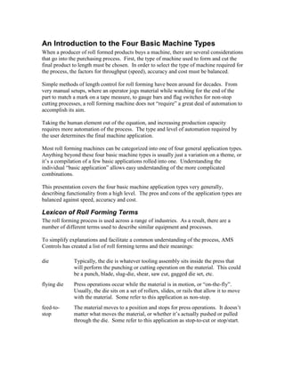
The chart below graphically represents the relationships between speed, accuracy and
cost amongst the machine types. Accuracy and speed are represented along the X and Y
axes, respectively, while cost is a function of the size of the points. From the perspective
of the electrical control system, closed loop systems are approximately 30% more
expensive than open loop systems.
5. Speed, Accuracy and Cost Relationships
When weighing the three factors against each other, usually two factors will win out over
the third. If low cost and high accuracy are important concerns, throughput will likely be
lower. If accuracy and throughput are important, the system will cost more.
Open Loop Feed-to-Stop
The more accurate of the two open loop length control methods, feed-to-stop machines
have lower through-put rates than flying applications. These characteristics are balanced
against cost, which is lower for open loop systems.
Feed-to-stop systems use a press with a fixed-base die. The actuation method of the press
is unimportant; it could be hydraulic, pneumatic or mechanical. The important aspect of
this press is that the die is fixed in its position and cannot move.
6. Hydraulic Press with Fixed Base Die
In feed-to-stop applications it is the material that is positioned by the machine. The
length control system must start and stop the material so the correct length is past the exit
side of the cut off die before the press is fired. The accuracy and repeatability of part
lengths is tied to the machine’s ability to bring the material to a stop at the same rate
from move to move.
On post cut machines, the material is formed before it is cut to length. The inertia of the
material changes based on the length of part formed. If the machine can not compensate
for the changing inertia, the stopping rate will change and accuracy will suffer.
Open Loop Feed-to-Stop Post Cut Line
In a pre-cut feed-to-stop roll forming process, the material is fed by a set of rolls driven
by an AC motor. Parts are cut to length, and then ride along a conveyor belt to the roll
former.
7. Open Loop Feed-to-Stop Pre-Cut Line
While pre-cut lines are generally slower than their post cut cousins, the equipment
maintenance expenses are lower. The roll former runs at a constant rate, which saves
wear and tear, and these systems generally have simpler cut off dies.
Open Loop Flying Die
In flying die applications, throughput is the key concern. These systems are capable of
high speeds, and accuracy could be as good as ± 0.032” (0.8128 mm). Like the open
loop feed-to-stop, these systems have a very low cost compared to closed loop systems.
The operation of most open loop flying die machines is simple. Material runs at a
consistent speed most of the time. Line speed might be adjusted by the operator, but
speed is usually only changed when part lengths change; shorter parts running at slower
speeds, longer parts at higher speeds.
When the correct length has been reached, the control system fires the press. The cut off
blade enters the material, and the material pushes the die forward while the cutting action
is taking place. When the cut is complete, the press retracts the blade out of the material,
and the die is returned to its originating (home) position. The return is usually
accomplished with springs or an air cylinder.
Open Loop Flying Die Post Cut Line
In some cases, the finished shape (profile) of the material is not strong enough to support
the weight of the die at the speed the machine is running. To keep the material from
being damaged, a boost cylinder can be mounted to the die. This cylinder might be
hydraulic or pneumatic, but its function is to push the die up to material speed as the
press is being fired. This helps to relieve the stress of the weight of the die on the
material.
8. Open Loop Flying Die with Boost
A boost cylinder can achieve accelerations over distances that are not possible without
very expensive and large servo equipment. This makes the boost a viable option when
accuracy is not critical for a high speed process.
Closed Loop Feed-to-Stop
Closed loop usually means a high degree of accuracy. Feed-to-stop systems have lower
throughput, but the tolerance for punching and cutting operations can be as good as
0.003” (0.0762 mm) or better. Closed loop servo systems tend to cost more than open
loop systems.
In the feed-to-stop application, a closed loop servo motor drives a set of feed rolls on the
entry side of a hydraulic press. Some systems will actually pull the material from the exit
side, but it’s still referred to as a “feeder system”. In this application, it’s typical to use
only the servo feedback as the measurement system.
Servo Feeder for Fixed Base Die
In some situations, slip is a known factor between the feed rolls and the material. When
slip is a problem, a material encoder can be added to the setup. Since the encoder wheel
9. is not driven, its position feedback should not be susceptible to slip. So, the control
system can close its position loop around the material encoder for accuracy.
Closed Loop Flying Die
Servo controlled flying die accelerator systems can achieve speeds in excess of 600 fpm
(183 mpm) and hold accuracies of ±0.015” (0.381 mm) or better. Though, usually
accuracy is traded for speed, it is possible to have both with the right equipment and
proper maintenance. These systems are usually the most expensive, due to the servo
system and the actuation equipment required to connect the servo to the die.
The servo systems in this application typically track the tooling to within 0.0001” –
0.0002” (0.00254 - 0.00508 mm). This allows for extremely tight velocity and position
matching of punch and cut targets on the material.
Closed Loop Flying Die Post Cut Line
In a typical example of this application, the cut off die is moved by a ball screw actuator.
A rotary servo motor is mounted to the back of the actuator and the shafts are connected
via a spline coupler. This tight mechanical coupling provides very accurate positioning.
The control system in this case is matching speed and position between the material and
the die.
The benefit of the closed loop flying die is high quality parts produced at high speed with
high accuracy. Because the material and the cutting surface are moving at the same
speed, the material incurs no stress from the cutoff press. Because the material cut point
and the shear blade are matched in their position, accuracy is high.
The cost of the system can be prohibitive, however. The faster the die must move, the
more often it must cycle and the heavier it is, the more expensive the equipment becomes
to move the die.
Special Applications
There are some machine applications that don’t fall neatly within the four basic machine
application types. Some are variations on a theme, such as the rotary crank closed loop
flying die accelerator. Most are simply combinations of the four basic applications.
The DARF system is such a combination. DARF is an acronym for Die Accelerator with
a Roll Feed. In the vast majority of these applications, the roll feed system is closed
loop, and used to control a pre-punch system. The die accelerator cutoff system is
usually closed loop, but is sometimes open loop, or controlled using a pick up finger and
10. pilot hole. So the phrase “closed loop DARF” would specifically relate to the closed loop
cutoff.
Closed Loop Feed-to-Stop Pre-Punch with Closed Loop Flying Die Cutoff (DARF)
A DARF is used in roll forming for a variety of reasons:
• When the formed part won’t accept a punch because of its shape or structural
integrity.
• When punching tolerances are critical.
• When the cutoff will destroy the finished shape, most of the material at the cut
point is removed by the pre-punch press, so the cutoff is simply “finishing the
cut”.
Even though the DARF is merely a combination of two of the four basic machine
application types, there are considerations that are specific to this application. Stretch is a
major concern, since holes are being pre-punched. Synchronizing the pre-punched parts
to the cutoff is another concern.
Conclusion
Most automated roll forming lines are comprised of one of four basic machine
application types. The rest are either very special applications, or they are a mix-and-
match setup of the four basic types. For the purpose of continuity and ease of
understanding, categorizing machine applications in this way to allow us to convey a
general understanding of a machine’s functions in just a few words.
Each roll forming application type has its pros and cons, balancing cost, accuracy and
throughput. The faster and more accurate a system must be, the more expensive it is
likely to be. Closed loop systems are generally more accurate than open loop systems,
but they are also more expensive.