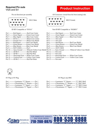
Required Pin outs
VGA and SV                                                                                              Product Instruction
                 Pin out directions per assembly                            All Connectors viewed from the front (mating) side.

                                                                       5         4        3        2        1
             1        2       3        4         5
                                                      HD15 Male                                                      HD15 Female
                                                                            10        9        8        7        6
       6         7        8        9        10
                                                                       15        14       13       12       11
           11        12       13       14        15


                 ID BIT Compatible or “SVGA”                                Non-ID BIT Compatible or “RGBHV”

Pin 1 -------Red Signal------------Red Coax Center                Pin 1 ----------Red Signal------------ Red Coax Center
Pin 2 -------Green Signal --------Green Coax Center               Pin 2 ----------Green Signal --------- Green Coax Center
Pin 3 -------Blue Signal ----------Blue Coax Center               Pin 3 ----------Blue Signal ----------- Blue Coax Center
Pin 4 -------ID bit 2 ---------------Black Coax Center            Pin 4 ----------Not used
Pin 5 -------Ground Test ---------Black Coax Shield               Pin 5 ----------Not used
Pin 6 -------Red Return ----------Red Coax Shield                 Pin 6 ----------Red Return ----------- Red Coax Shield
Pin 7 -------Green Return -------Green Coax Shield                Pin 7 ----------Green Return --------- Green Coax Shield
Pin 8 -------Blue Return ---------Blue Coax Shield                Pin 8 ----------Blue Return ---------- Blue Coax Shield
Pin 9 -------NOT USED----------Pin 9                              Pin 9 ----------NOT USED
Pin 10 ------Sync Ground --------White & Yellow Coax Shield       Pin 10 --------Sync Ground ---------- White & Yellow Coax Shield
Pin 11 ------ID Bit 0 --------------Red Pair-Black                Pin 11 --------Not used
Pin 12 ------ID Bit 1 --------------Red Pair-Red                  Pin 12 --------Not used
Pin 13 ------Horizontal Sync ----White Coax Center                Pin 13 --------Horizontal Sync ------ White Coax Center
Pin 14 ------Vertical Sync -------Yellow Coax Center              Pin 14 --------Vertical Sync --------- Yellow Coax Center
Pin 15 ------ID Bit 3 --------------Red Pair-Drain                Pin 15 --------Not used


       3 4

   1         2

   SV Plug


SV Plug to SV Plug                                                                             SV Plug to any BNC

Pin 1 ----------Luminance “Y” Return -------- Pin 1               Pin 1 ----------Luminance “Y” Return -------- “Y” BNC Shell
Pin 2 ----------Chrominance “C” Return------ Pin 2                Pin 2 ----------Chrominance “C” Return------ “C” BNC Shell
Pin 3 ----------Luminance “Y” Signal -------- Pin 3               Pin 3 ----------Luminance “Y” Signal -------- “Y” BNC Center
Pin 4 ----------Chrominance “C” Signal ------ Pin 4               Pin 4 ----------Chrominance “C” Signal ------ “C” BNC Center

Vga Sv Bnc Pin Outs

  • 1.
    Required Pin outs VGAand SV Product Instruction Pin out directions per assembly All Connectors viewed from the front (mating) side. 5 4 3 2 1 1 2 3 4 5 HD15 Male HD15 Female 10 9 8 7 6 6 7 8 9 10 15 14 13 12 11 11 12 13 14 15 ID BIT Compatible or “SVGA” Non-ID BIT Compatible or “RGBHV” Pin 1 -------Red Signal------------Red Coax Center Pin 1 ----------Red Signal------------ Red Coax Center Pin 2 -------Green Signal --------Green Coax Center Pin 2 ----------Green Signal --------- Green Coax Center Pin 3 -------Blue Signal ----------Blue Coax Center Pin 3 ----------Blue Signal ----------- Blue Coax Center Pin 4 -------ID bit 2 ---------------Black Coax Center Pin 4 ----------Not used Pin 5 -------Ground Test ---------Black Coax Shield Pin 5 ----------Not used Pin 6 -------Red Return ----------Red Coax Shield Pin 6 ----------Red Return ----------- Red Coax Shield Pin 7 -------Green Return -------Green Coax Shield Pin 7 ----------Green Return --------- Green Coax Shield Pin 8 -------Blue Return ---------Blue Coax Shield Pin 8 ----------Blue Return ---------- Blue Coax Shield Pin 9 -------NOT USED----------Pin 9 Pin 9 ----------NOT USED Pin 10 ------Sync Ground --------White & Yellow Coax Shield Pin 10 --------Sync Ground ---------- White & Yellow Coax Shield Pin 11 ------ID Bit 0 --------------Red Pair-Black Pin 11 --------Not used Pin 12 ------ID Bit 1 --------------Red Pair-Red Pin 12 --------Not used Pin 13 ------Horizontal Sync ----White Coax Center Pin 13 --------Horizontal Sync ------ White Coax Center Pin 14 ------Vertical Sync -------Yellow Coax Center Pin 14 --------Vertical Sync --------- Yellow Coax Center Pin 15 ------ID Bit 3 --------------Red Pair-Drain Pin 15 --------Not used 3 4 1 2 SV Plug SV Plug to SV Plug SV Plug to any BNC Pin 1 ----------Luminance “Y” Return -------- Pin 1 Pin 1 ----------Luminance “Y” Return -------- “Y” BNC Shell Pin 2 ----------Chrominance “C” Return------ Pin 2 Pin 2 ----------Chrominance “C” Return------ “C” BNC Shell Pin 3 ----------Luminance “Y” Signal -------- Pin 3 Pin 3 ----------Luminance “Y” Signal -------- “Y” BNC Center Pin 4 ----------Chrominance “C” Signal ------ Pin 4 Pin 4 ----------Chrominance “C” Signal ------ “C” BNC Center