Download to read offline
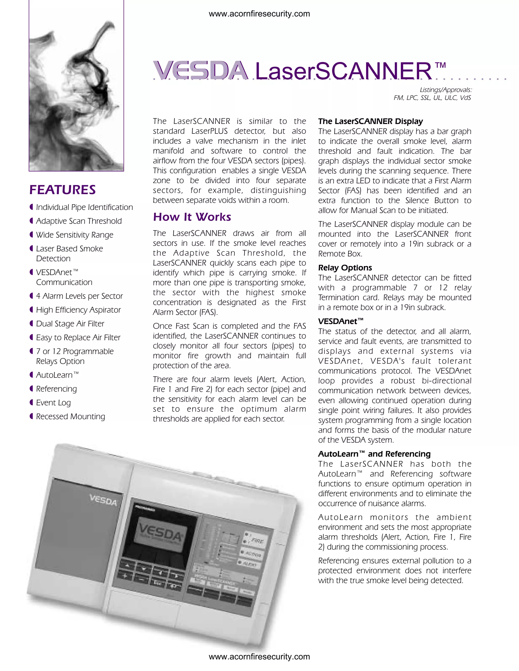

The LaserSCANNER is a VESDA air sampling smoke detector that can divide its detection area into four separate sectors. It draws air from all sectors and uses a laser to quickly scan and identify which sector is carrying smoke during an alarm. It has adjustable alarm thresholds for each sector to optimize detection. Key features include individual sector identification and monitoring, adaptive scanning, VESDAnet communication, and software for automatic setup and environmental compensation.


