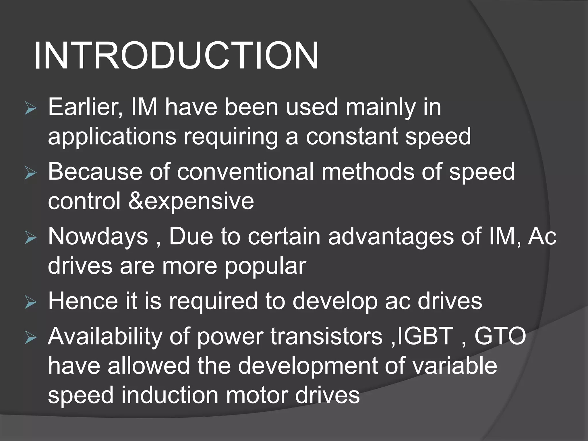
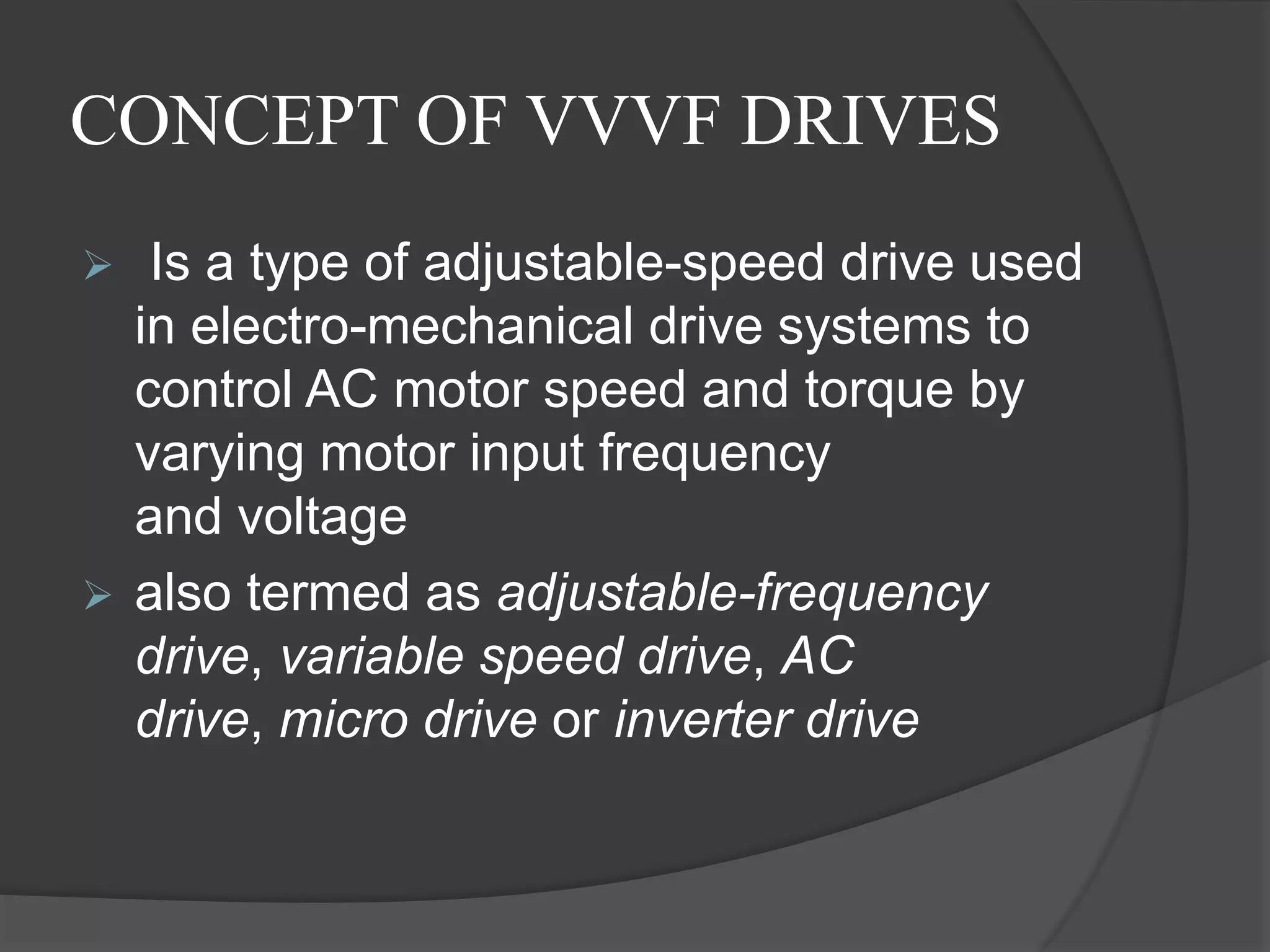
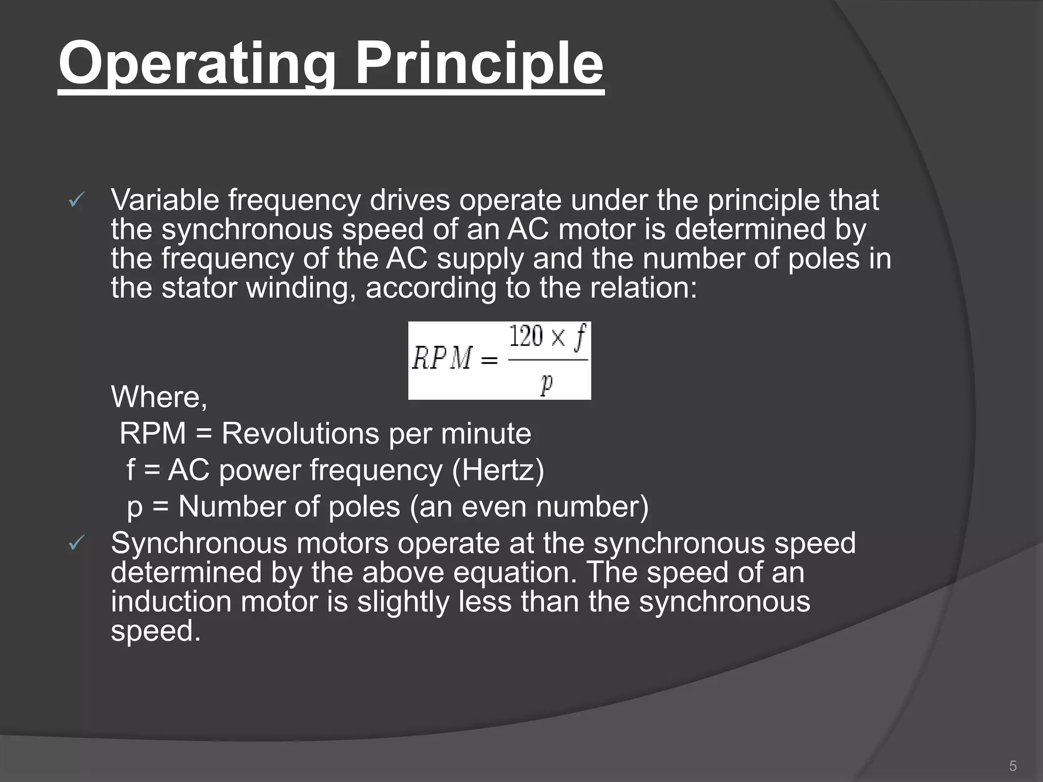
Presented by:
BHEEMANNA ANGADI
[1OX13EE020]
The Oxford college of engg-bangalore
1
VARIABLE VOLTAGE VARIABLE FREQUENCY
DRIVES
CONTENTS
 INTRODUCTION
 DRIVE OPERATION PRINCIPLE
 SYSTEM DESCRIPTION
 VVVFD CONTROLLER
 SPWM TECHNIQUE
 POWER RATINGS
 ADVANTAGES & APPLICATIONS
 DRAWBACKS
 CONCLUSION
INTRODUCTION
 Earlier, IM have been used mainly in
applications requiring a constant speed
 Because of conventional methods of speed
control &expensive
 Nowdays , Due to certain advantages of IM, Ac
drives are more popular
 Hence it is required to develop ac drives
 Availability of power transistors ,IGBT , GTO
have allowed the development of variable
speed induction motor drives
CONCEPT OF VVVF DRIVES
 Is a type of adjustable-speed drive used
in electro-mechanical drive systems to
control AC motor speed and torque by
varying motor input frequency
and voltage
 also termed as adjustable-frequency
drive, variable speed drive, AC
drive, micro drive or inverter drive
Operating Principle
 Variable frequency drives operate under the principle that
the synchronous speed of an AC motor is determined by
the frequency of the AC supply and the number of poles in
the stator winding, according to the relation:
Where,
RPM = Revolutions per minute
f = AC power frequency (Hertz)
p = Number of poles (an even number)
 Synchronous motors operate at the synchronous speed
determined by the above equation. The speed of an
induction motor is slightly less than the synchronous
speed.
5
Contd…
 Stator voltage V1 =fΦ
 Voltage induced in stator is proportional to the product of
supply frequencies and flux.
 Any reduction in supply frequencies without change in
terminal voltage causes an increase air gap flux.
 The increase in flux will saturate the motor.
 Decrease in flux is also avoided to retain the torque
capability of motor
 Therefore the variable frequency control below the rated
frequency is generally carried out at rated air-gap flux by
varying the terminal voltage with frequency so as to
maintain (V/F) ratio constant at rated value.
6
SYSTEM DESCRIPTION
A VFD in a block
diagram.
Rectifier:
The rectifier in a VFD is used to convert incoming
ac power into direct current (dc) power.
DC bus:
DC output of rectifier flows through the dc link
to inverter input.
Any ripple must be smoothed out before any
transistor switches “on”. If not, this distortion will
show up in the output to the Motor
Inverter:
The “Insulated Gate Bipolar Transistor” (IGBT)
is a common choice in modern VFDs.
The IGBT can switch on and off several
thousand times per second and precisely control
the power delivered to the motor.
The IGBT uses a method named “pulse width
modulation” (PWM) to simulate a current sine
wave at the desired frequency to the motor.
VVVFD Controller
. 9
SPWM TECHINIQUE FOR v/f
V/F = Constant
v=voltage and f=frequency, c= constant
 In sinusoidal pulse width modulation there are
multiple pulses per half-cycle and the width of
the each pulse is varied with respect to the sine
wave magnitude corresponding to that
duration.
 In order to achieve the constant ratio ,we have
to fire the (IGBT )in such way that the
amplitude of output voltage waveform in a cycle
will maintain the v/f ratio according the
frequency change.
Waveforms are shown on next slide
10
Pulse-width-modulated voltage
and current waveforms
ADVANTAGES
 Large energy savings at lower speed.
 Increased life of rotating components
due to lower operating speed.
 Reduced noise and vibration level.
 Reduction of thermal and mechanical
stresses.
 Lower KVA Rating
 High power factor
APPLICATIONS
 Fans
 Blowers
 Mill run-out tablets
 Cranes
 Conveyers
 Traction etc……
DRAWBACKS
 Power converters for the control of ac
motors are more complex.
 Power converter for ac drives are more
expensive.
 Power converters for ac drives generate
harmonics in the supply system and
load circuit.
Variable voltage variable frequency drive

Variable voltage variable frequency drive

  • 1.
    Presented by: BHEEMANNA ANGADI [1OX13EE020] TheOxford college of engg-bangalore 1 VARIABLE VOLTAGE VARIABLE FREQUENCY DRIVES
  • 2.
    CONTENTS  INTRODUCTION  DRIVEOPERATION PRINCIPLE  SYSTEM DESCRIPTION  VVVFD CONTROLLER  SPWM TECHNIQUE  POWER RATINGS  ADVANTAGES & APPLICATIONS  DRAWBACKS  CONCLUSION
  • 3.
    INTRODUCTION  Earlier, IMhave been used mainly in applications requiring a constant speed  Because of conventional methods of speed control &expensive  Nowdays , Due to certain advantages of IM, Ac drives are more popular  Hence it is required to develop ac drives  Availability of power transistors ,IGBT , GTO have allowed the development of variable speed induction motor drives
  • 4.
    CONCEPT OF VVVFDRIVES  Is a type of adjustable-speed drive used in electro-mechanical drive systems to control AC motor speed and torque by varying motor input frequency and voltage  also termed as adjustable-frequency drive, variable speed drive, AC drive, micro drive or inverter drive
  • 5.
    Operating Principle  Variablefrequency drives operate under the principle that the synchronous speed of an AC motor is determined by the frequency of the AC supply and the number of poles in the stator winding, according to the relation: Where, RPM = Revolutions per minute f = AC power frequency (Hertz) p = Number of poles (an even number)  Synchronous motors operate at the synchronous speed determined by the above equation. The speed of an induction motor is slightly less than the synchronous speed. 5
  • 6.
    Contd…  Stator voltageV1 =fΦ  Voltage induced in stator is proportional to the product of supply frequencies and flux.  Any reduction in supply frequencies without change in terminal voltage causes an increase air gap flux.  The increase in flux will saturate the motor.  Decrease in flux is also avoided to retain the torque capability of motor  Therefore the variable frequency control below the rated frequency is generally carried out at rated air-gap flux by varying the terminal voltage with frequency so as to maintain (V/F) ratio constant at rated value. 6
  • 7.
    SYSTEM DESCRIPTION A VFDin a block diagram.
  • 8.
    Rectifier: The rectifier ina VFD is used to convert incoming ac power into direct current (dc) power. DC bus: DC output of rectifier flows through the dc link to inverter input. Any ripple must be smoothed out before any transistor switches “on”. If not, this distortion will show up in the output to the Motor Inverter: The “Insulated Gate Bipolar Transistor” (IGBT) is a common choice in modern VFDs. The IGBT can switch on and off several thousand times per second and precisely control the power delivered to the motor. The IGBT uses a method named “pulse width modulation” (PWM) to simulate a current sine wave at the desired frequency to the motor.
  • 9.
  • 10.
    SPWM TECHINIQUE FORv/f V/F = Constant v=voltage and f=frequency, c= constant  In sinusoidal pulse width modulation there are multiple pulses per half-cycle and the width of the each pulse is varied with respect to the sine wave magnitude corresponding to that duration.  In order to achieve the constant ratio ,we have to fire the (IGBT )in such way that the amplitude of output voltage waveform in a cycle will maintain the v/f ratio according the frequency change. Waveforms are shown on next slide 10
  • 11.
  • 13.
    ADVANTAGES  Large energysavings at lower speed.  Increased life of rotating components due to lower operating speed.  Reduced noise and vibration level.  Reduction of thermal and mechanical stresses.  Lower KVA Rating  High power factor
  • 14.
    APPLICATIONS  Fans  Blowers Mill run-out tablets  Cranes  Conveyers  Traction etc……
  • 15.
    DRAWBACKS  Power convertersfor the control of ac motors are more complex.  Power converter for ac drives are more expensive.  Power converters for ac drives generate harmonics in the supply system and load circuit.