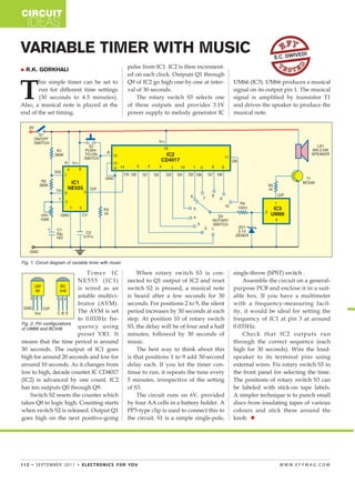
CIRCUIT
    IDEAS

VARIABLE TIMER WITH MUSIC                                                                                                S.C. DWIV
                                                                                                                                    EDI

   R.K. GORKHALI                                            pulse from IC1. IC2 is then increment-
                                                             ed on each clock. Outputs Q1 through


T
       his simple timer can be set to                        Q9 of IC2 go high one-by-one at inter-      UM66 (IC3). UM66 produces a musical
       run for different time settings                       val of 30 seconds.                          signal on its output pin 1. The musical
       (30 seconds to 4.5 minutes).                              The rotary switch S3 selects one        signal is amplified by transistor T1
Also, a musical note is played at the                        of these outputs and provides 3.1V          and drives the speaker to produce the
end of the set timing.                                       power supply to melody generator IC         musical note.


Fig. 1: Circuit diagram of variable timer with music

                               Timer IC                          When rotary switch S3 is con-           single-throw (SPST) switch .
                           NE555 (IC1)                       nected to Q1 output of IC2 and reset            Assemble the circuit on a general-
                           is wired as an                    switch S2 is pressed, a musical note        purpose PCB and enclose it in a suit-
                           astable multivi-                  is heard after a few seconds for 30         able box. If you have a multimeter
                           brator (AVM).                     seconds. For positions 2 to 9, the silent   with a frequency-measuring facil-
                           The AVM is set                    period increases by 30 seconds at each      ity, it would be ideal for setting the
                           to 0.033Hz fre-                   step. At position 10 of rotary switch       frequency of IC1 at pin 3 at around
Fig. 2: Pin configurations
of UM66 and BC548          quency using                      S3, the delay will be of four and a half    0.033Hz.
                           preset VR1. It                    minutes, followed by 30 seconds of              Check that IC2 outputs run
means that the time period is around                         music.                                      through the correct sequence (each
30 seconds. The output of IC1 goes                               The best way to think about this        high for 30 seconds). Wire the loud-
high for around 20 seconds and low for                       is that positions 1 to 9 add 30-second      speaker to its terminal pins using
around 10 seconds. As it changes from                        delay each. If you let the timer con-       external wires. Fix rotary switch S3 in
low to high, decade counter IC CD4017                        tinue to run, it repeats the tune every     the front panel for selecting the time.
(IC2) is advanced by one count. IC2                          5 minutes, irrespective of the setting      The positions of rotary switch S3 can
has ten outputs Q0 through Q9.                               of S3.                                      be labeled with stick-on tape labels.
     Switch S2 resets the counter which                          The circuit runs on 6V, provided        A simpler technique is to punch small
takes Q0 to logic high. Counting starts                      by four AA cells in a battery holder. A     discs from insulating tapes of various
when switch S2 is released. Output Q1                        PP3-type clip is used to connect this to    colours and stick these around the
goes high on the next positive-going                         the circuit. S1 is a simple single-pole,    knob. 


1 1 2 • S E P T E M B E R 2 0 1 1 • E L E C T RO N I C S F O R YO U                                                        W W W. E F Y M AG . CO M

Vari timer with music

  • 1.
    CIRCUIT IDEAS VARIABLE TIMER WITH MUSIC S.C. DWIV EDI  R.K. GORKHALI pulse from IC1. IC2 is then increment- ed on each clock. Outputs Q1 through T his simple timer can be set to Q9 of IC2 go high one-by-one at inter- UM66 (IC3). UM66 produces a musical run for different time settings val of 30 seconds. signal on its output pin 1. The musical (30 seconds to 4.5 minutes). The rotary switch S3 selects one signal is amplified by transistor T1 Also, a musical note is played at the of these outputs and provides 3.1V and drives the speaker to produce the end of the set timing. power supply to melody generator IC musical note. Fig. 1: Circuit diagram of variable timer with music Timer IC When rotary switch S3 is con- single-throw (SPST) switch . NE555 (IC1) nected to Q1 output of IC2 and reset Assemble the circuit on a general- is wired as an switch S2 is pressed, a musical note purpose PCB and enclose it in a suit- astable multivi- is heard after a few seconds for 30 able box. If you have a multimeter brator (AVM). seconds. For positions 2 to 9, the silent with a frequency-measuring facil- The AVM is set period increases by 30 seconds at each ity, it would be ideal for setting the to 0.033Hz fre- step. At position 10 of rotary switch frequency of IC1 at pin 3 at around Fig. 2: Pin configurations of UM66 and BC548 quency using S3, the delay will be of four and a half 0.033Hz. preset VR1. It minutes, followed by 30 seconds of Check that IC2 outputs run means that the time period is around music. through the correct sequence (each 30 seconds. The output of IC1 goes The best way to think about this high for 30 seconds). Wire the loud- high for around 20 seconds and low for is that positions 1 to 9 add 30-second speaker to its terminal pins using around 10 seconds. As it changes from delay each. If you let the timer con- external wires. Fix rotary switch S3 in low to high, decade counter IC CD4017 tinue to run, it repeats the tune every the front panel for selecting the time. (IC2) is advanced by one count. IC2 5 minutes, irrespective of the setting The positions of rotary switch S3 can has ten outputs Q0 through Q9. of S3. be labeled with stick-on tape labels. Switch S2 resets the counter which The circuit runs on 6V, provided A simpler technique is to punch small takes Q0 to logic high. Counting starts by four AA cells in a battery holder. A discs from insulating tapes of various when switch S2 is released. Output Q1 PP3-type clip is used to connect this to colours and stick these around the goes high on the next positive-going the circuit. S1 is a simple single-pole, knob.  1 1 2 • S E P T E M B E R 2 0 1 1 • E L E C T RO N I C S F O R YO U W W W. E F Y M AG . CO M