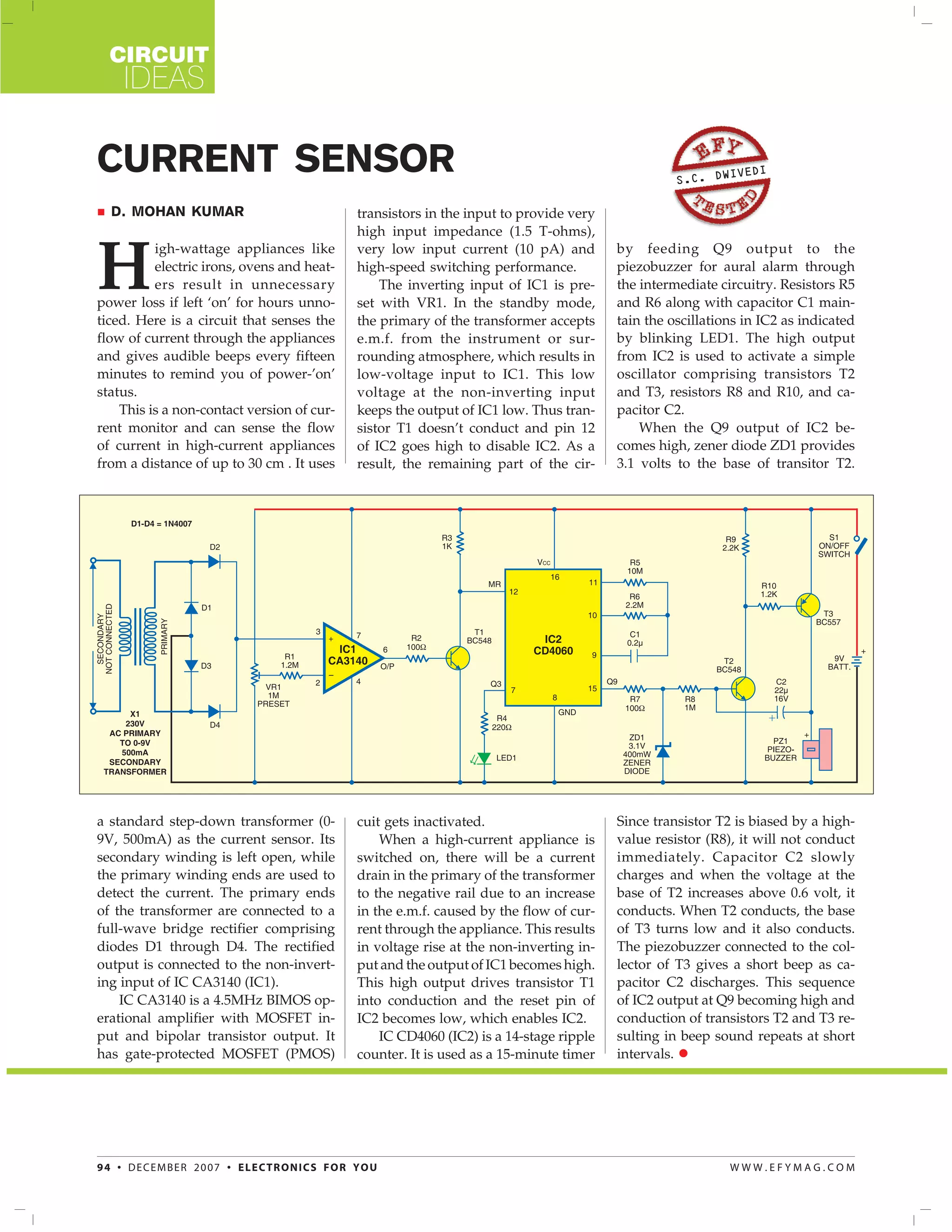
CIRCUIT
    IDEAS

CURRENT SENSOR                                                                                   S.C. DW
                                                                                                        IVEDI


  D. MOHAN KUMAR                            transistors in the input to provide very
                                            high input impedance (1.5 T-ohms),


H
          igh-wattage appliances like       very low input current (10 pA) and         by feeding Q9 output to the
          electric irons, ovens and heat-   high-speed switching performance.          piezobuzzer for aural alarm through
          ers result in unnecessary             The inverting input of IC1 is pre-     the intermediate circuitry. Resistors R5
power loss if left ‘on’ for hours unno-     set with VR1. In the standby mode,         and R6 along with capacitor C1 main-
ticed. Here is a circuit that senses the    the primary of the transformer accepts     tain the oscillations in IC2 as indicated
flow of current through the appliances      e.m.f. from the instrument or sur-         by blinking LED1. The high output
and gives audible beeps every fifteen       rounding atmosphere, which results in      from IC2 is used to activate a simple
minutes to remind you of power-’on’         low-voltage input to IC1. This low         oscillator comprising transistors T2
status.                                     voltage at the non-inverting input         and T3, resistors R8 and R10, and ca-
    This is a non-contact version of cur-   keeps the output of IC1 low. Thus tran-    pacitor C2.
rent monitor and can sense the flow         sistor T1 doesn’t conduct and pin 12           When the Q9 output of IC2 be-
of current in high-current appliances       of IC2 goes high to disable IC2. As a      comes high, zener diode ZD1 provides
from a distance of up to 30 cm . It uses    result, the remaining part of the cir-     3.1 volts to the base of transitor T2.


a standard step-down transformer (0-        cuit gets inactivated.                     Since transistor T2 is biased by a high-
9V, 500mA) as the current sensor. Its           When a high-current appliance is       value resistor (R8), it will not conduct
secondary winding is left open, while       switched on, there will be a current       immediately. Capacitor C2 slowly
the primary winding ends are used to        drain in the primary of the transformer    charges and when the voltage at the
detect the current. The primary ends        to the negative rail due to an increase    base of T2 increases above 0.6 volt, it
of the transformer are connected to a       in the e.m.f. caused by the flow of cur-   conducts. When T2 conducts, the base
full-wave bridge rectifier comprising       rent through the appliance. This results   of T3 turns low and it also conducts.
diodes D1 through D4. The rectified         in voltage rise at the non-inverting in-   The piezobuzzer connected to the col-
output is connected to the non-invert-      put and the output of IC1 becomes high.    lector of T3 gives a short beep as ca-
ing input of IC CA3140 (IC1).               This high output drives transistor T1      pacitor C2 discharges. This sequence
    IC CA3140 is a 4.5MHz BIMOS op-         into conduction and the reset pin of       of IC2 output at Q9 becoming high and
erational amplifier with MOSFET in-         IC2 becomes low, which enables IC2.        conduction of transistors T2 and T3 re-
put and bipolar transistor output. It           IC CD4060 (IC2) is a 14-stage ripple   sulting in beep sound repeats at short
has gate-protected MOSFET (PMOS)            counter. It is used as a 15-minute timer   intervals.


94 • DECEMBER 2007 • ELECTRONICS FOR YOU                                                                  WWW.EFYMAG.COM

Current sensor

  • 1.
    CIRCUIT IDEAS CURRENT SENSOR S.C. DW IVEDI D. MOHAN KUMAR transistors in the input to provide very high input impedance (1.5 T-ohms), H igh-wattage appliances like very low input current (10 pA) and by feeding Q9 output to the electric irons, ovens and heat- high-speed switching performance. piezobuzzer for aural alarm through ers result in unnecessary The inverting input of IC1 is pre- the intermediate circuitry. Resistors R5 power loss if left ‘on’ for hours unno- set with VR1. In the standby mode, and R6 along with capacitor C1 main- ticed. Here is a circuit that senses the the primary of the transformer accepts tain the oscillations in IC2 as indicated flow of current through the appliances e.m.f. from the instrument or sur- by blinking LED1. The high output and gives audible beeps every fifteen rounding atmosphere, which results in from IC2 is used to activate a simple minutes to remind you of power-’on’ low-voltage input to IC1. This low oscillator comprising transistors T2 status. voltage at the non-inverting input and T3, resistors R8 and R10, and ca- This is a non-contact version of cur- keeps the output of IC1 low. Thus tran- pacitor C2. rent monitor and can sense the flow sistor T1 doesn’t conduct and pin 12 When the Q9 output of IC2 be- of current in high-current appliances of IC2 goes high to disable IC2. As a comes high, zener diode ZD1 provides from a distance of up to 30 cm . It uses result, the remaining part of the cir- 3.1 volts to the base of transitor T2. a standard step-down transformer (0- cuit gets inactivated. Since transistor T2 is biased by a high- 9V, 500mA) as the current sensor. Its When a high-current appliance is value resistor (R8), it will not conduct secondary winding is left open, while switched on, there will be a current immediately. Capacitor C2 slowly the primary winding ends are used to drain in the primary of the transformer charges and when the voltage at the detect the current. The primary ends to the negative rail due to an increase base of T2 increases above 0.6 volt, it of the transformer are connected to a in the e.m.f. caused by the flow of cur- conducts. When T2 conducts, the base full-wave bridge rectifier comprising rent through the appliance. This results of T3 turns low and it also conducts. diodes D1 through D4. The rectified in voltage rise at the non-inverting in- The piezobuzzer connected to the col- output is connected to the non-invert- put and the output of IC1 becomes high. lector of T3 gives a short beep as ca- ing input of IC CA3140 (IC1). This high output drives transistor T1 pacitor C2 discharges. This sequence IC CA3140 is a 4.5MHz BIMOS op- into conduction and the reset pin of of IC2 output at Q9 becoming high and erational amplifier with MOSFET in- IC2 becomes low, which enables IC2. conduction of transistors T2 and T3 re- put and bipolar transistor output. It IC CD4060 (IC2) is a 14-stage ripple sulting in beep sound repeats at short has gate-protected MOSFET (PMOS) counter. It is used as a 15-minute timer intervals. 94 • DECEMBER 2007 • ELECTRONICS FOR YOU WWW.EFYMAG.COM