1. A Device for Imaging Multiple Samples Concurrently on an
Optical Coherence Tomography Microscope
Optical Coherence Tomography (OCT) is a
real time imaging method that acquires 3-
dimensional images of tissue structure with
high resolution in all dimensions without the
need for labels. The LLTech Light-CT
microscope has been used in the lab to study
biofilms and excised tissue structure.
Currently, work is underway to use the OCT to
examine drosophila (fruit flies) morphology.
The existing imaging platform, is capable of
automatically acquiring several images of a
single location over a period of time (time-
series acquisition). This one-at-a-time method
becomes both labour intensive and time
consuming when a large number of smaller
samples (eg. drosophila) are imaged.
Background Design and Prototype
Acknowledgements and References
Conclusion and Future Directions
Results
Kandice Lau ‡,‖, and Christopher M. Yip‖,§,¶
‡Division of Engineering Science; ‖Institute of Biomaterials and Biomedical Engineering;§Department of Chemical Engineering and Applied Chemistry; ¶Department of Biochemistry
Donnelly Centre for Cellular and Biomolecular Research, University of Toronto, 160 College St, Toronto, Canada M5S 3E1
Sample Dish
Concept
Figure 1: The LLTech Light-CT
Microscope
Objective: Create a device that allows the user to place several samples on the
sample dish and image all of them automatically with time-series capability.
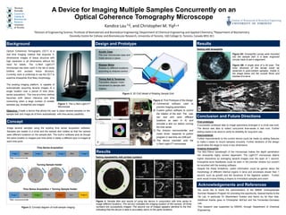
Image several samples using the existing time series acquisition software.
Samples are loaded in a circle and the sample dish rotates so that the camera
sees different locations on the sample dish. The built-in software acts as though
the same location is imaged over time while in reality a different spot is imaged at
each time point.
Testing repeatability with printed numbers
t = 0min 5min 10min
15min 20min 25min
Figure 5: Sample dish and results of using the device in conjunction with time series to
image different locations. The red box indicates the imaging location of the camera. All three
numbers are successfully imaged. The second row of images appears identical to the first,
indicating that the device is able to accurately return to the same locations.
Testing with drosophila
Figure 6A: Drosophila Larvae were mounted
into the sample dish in a laser engraved
circular track to aid in alignment.
Figure 6B: A single slice of a 3d scan. The
inner structure of the larvae could be
observed in post-mortem samples. Visible in
the image below are the muscle fibres and
trachea of a larva
Results
We would like to thank the administrators of the IBBME Undergraduate
Summer Research Program for providing this opportunity. Special thanks to the
Yip Lab, in particular Dr. Maximiliano Guiliani and Aaron Au for their help.
Additional thanks goes to Christopher McFaul and the Fernandez-Gonzalez
Lab.
This research was supported by NSERC through Department of Chemical
Engineering.
First prototype
A successful prototype able to image specimens arranged in a circle was built.
The device was able to collect concurrent time-series in test runs. Further
testing needs to be done to verify its reliability for long-term use.
Improvements
Further improvements to the current device could be made by adding features
to make it easier to mount samples circularly. Further iterations of the design
would allow the stage to move in two dimensions.
Imaging drosophila
The 600-700nm wavelength of the microscope makes the depth penetration
into drosophila highly context dependant. The Light-CT microscope attains
higher resolutions by averaging several images over the span of 1 second.
Drosophila larva heartbeats could be seen in the preview window but couldn’t
be recorded with the existing software.
Despite the these limitations, useful information could be gained about the
morphology of different internal organs in larva and processes slower than 1
second, such as growth and the dynamics of the digestive system. Further
work would involve finding a means to immobilize samples and orient
Muscle Fibres Trachea
Timing Belt & Tensioner
Translates stepper motor
movement to sample dish
rotation
Acrylic Case
Fits over microscope case and
holds device in place
Stepper Motor
Rotates to different locations
according to Arduino control
Figure 3: 3D CAD Model of Rotating Sample Dish
Figure 4: First Prototype of the Design
A) Commercial software used to
preview imaging parameters
B) Custom python software to control
the rotation of the dish. The user
can test and save different
locations as seen in A) and
simulate a test run before running
the time series
C) The Arduino microcontroller and
motor driver, responds to python
program in real time via USB port
D) The device mounted onto the
LLTech Light-CT microscope.
A
B
C
D
Time Series Acquisition
Turning Sample Holder
Time
Image 1 Image 2 Image 3 Image 4Wait Wait Wait
Time
Image 1 Image 2 Image 3 Image 4Turn Turn Turn
Time Series Acquisition + Turning Sample Holder
Figure 2: Concept diagram of multi-sample imaging
A
B