This document is a user manual for the Conzerv EM6400 Series Power Meters. It contains the following key information:
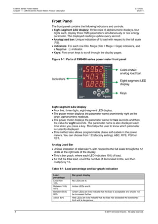
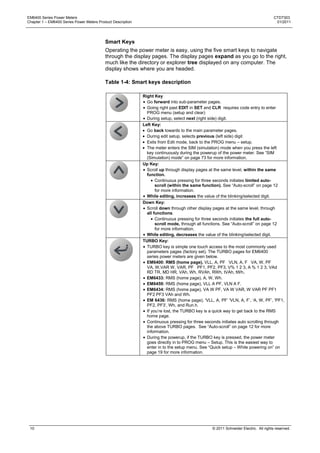
1. It describes the physical features of the EM6400 Series Power Meters including the front panel display and keys, and rear panel connections.
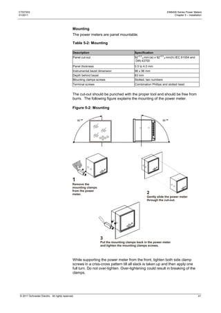
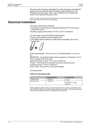
2. It provides safety warnings and precautions for installing and operating the power meters.
3. It gives an overview of the models and measurement parameters that are available in the EM6400 Series.
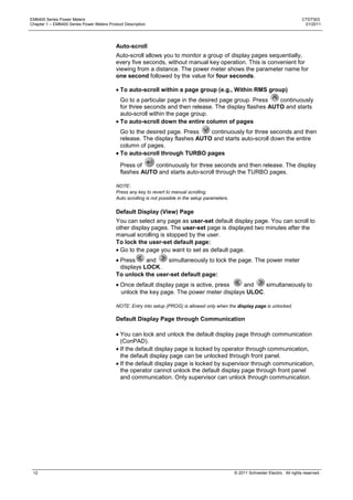
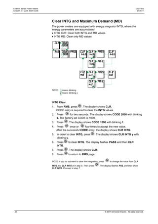
4. It includes quick start instructions for basic setup and configuration of the power meters through the front panel keys and display.
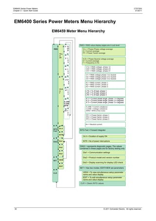
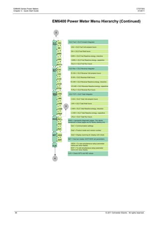
5. It outlines the menu hierarchy and functions for viewing and editing meter settings and measurement values.