Download to read offline
![US 2013/0014858 A1
TIRE SEALANT DELIVERY SYSTEM
FIELD OF THE INVENTION
[0001] The invention relates to a tire sealant delivery sys
tem, and more particularly, to a tire sealant delivery system
for selectively dispensing sealant or compressed air to a
receiving tire.
BACKGROUND OF THE INVENTION
[0002] Representative ofthe art is US. Pat. No. 5,908,145
Which discloses a housing of length and cross-sectional
dimension to enclose a given amount of tire sealing ?uid is
selected, coupled With a ?exible hose at its output port With a
pneumatic tire valve, and charged at its input port from a
source ofcompressed air to inject the tire sealing ?uid Within
the housing bymeans ofthehosethroughthepneumatic valve
to protect a tire against later bloWouts or puncturing in use. In
a preferred embodiment, the housing is constructed ofa poly
vinylchloride tube, While the hose is constructed of a clear
vinyl composition.
[0003] What is needed is a tire sealant delivery system for
selectively dispensing sealant or compressed air to a receiv
ing tire. The present invention meets this need.
SUMMARY OF THE INVENTION
[0004] The primary aspect ofthe invention is a tire sealant
delivery system for selectively dispensing sealant or com
pressed air to a receiving tire.
[0005] Other aspects ofthe invention Will be pointed out or
made obvious by the folloWing description of the invention
and the accompanying draWings.
[0006] The invention comprises a tire sealant delivery sys
tem comprising a container, a moveable piston disposed
Within the container, the moveable piston cooperatively
engage able With the container such that the piston does not
rotate during operation, a threaded shaft cooperatively
engaged With the piston and the container, a tube for connect
ing the container to a receiver, a dispenser comprising, an
electric actuator, the electric actuator connectable to the con
tainer for rotating the threaded shaft, an air compressor, and a
valve connectable to the container and connected to the air
compressor, the valve operable to selectively alloW dispens
ing of a tire sealant from the container to a receiving tire, or
dispensing of compressed air from the air compressor to a
receiving tire.
BRIEF DESCRIPTION OF THE DRAWINGS
[0007] The accompanying draWings, Which are incorpo
rated in and form a part of the speci?cation, illustrate pre
ferred embodiments of the present invention, and together
With a description, serve to explainthe principles ofthe inven
tion.
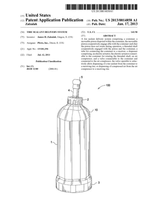
[0008] FIG. 1 is a perspective vieW of the container.
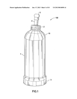
[0009] FIG. 2 is an exploded vieW of the container.
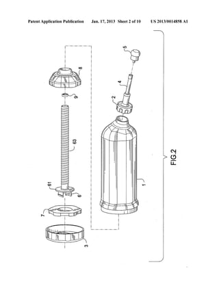
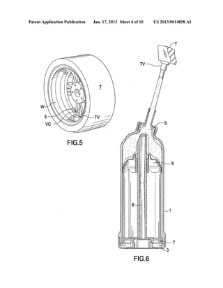
[0010] FIG. 3 is a cut-aWay vieW of the container.
[0011] FIG. 4 is a detail of the valve core tool.
[0012] FIG. 5 is a perspective vieW ofthe valve core tool in
use on a tire.
[0013] FIG. 6 is a cut-aWay vieW ofthe container in use on
a tire.
[0014] FIG. 7 is a perspective vieW ofthe tire ?lling system.
[0015] FIG. 8 is a detail vieW of the piston actuator.
[0016] FIG. 9 is a detail of the air compressor.
Jan. 17,2013
[0017] FIG. 10 is a cut-aWay vieW ofthe tire ?lling system.
[0018] FIG. 11 is a cut-aWay vieW ofthe tire ?lling system.
[0019] FIG. 12 is a cut-aWay vieW ofthe one-Way valve.
[0020] FIG. 13 is a cross-sectional vieW of the one-Way
valve in a ?rst operating mode.
[0021] FIG. 14 is a cross-sectional vieW of the one-Way
valve in a second operating mode.
[0022] FIG. 15 is a perspective vieW of the piston.
[0023] FIG. 16 is a perspective vieW of the bearing.
[0024] FIG. 17 is a perspective vieW of the threaded shaft.
[0025] FIG. 18 is a perspective vieW of the rotor.
[0026] FIG. 19 is a detail side vieW ofan end ofthe threaded
shaft.
DETAILED DESCRIPTION OF THE PREFERRED
EMBODIMENT
[0027] FIG. 1 is a perspective vieW of the container. Con
tainer 100 comprises a body 1, cap 2 and rotor 3. Cap 2 is
disposed on an end that is opposite the rotor 3. Body 1 is
generally cylindrical. An end 10 is hemispherical in form in
order to accommodate the piston as more fully described
herein. A typical sealant capacity ofthe body is 16 OZ.
[0028] FIG. 2 is an exploded vieW ofthe container. Bearing
7 is fastened to the end ofthe body. Bearing 7 seals the body
in Which the sealant is contained. Threaded shaft 6 extends
through bearing 7. A ?rst end 61 connects to rotor 3. A second
end 62 connects to the piston 8. Shaft cap 9 is disposed
betWeen threaded shaft 6 and piston 8.
[0029] A ?exible tube 4 extends from cap 2. Threaded to the
end oftube 4 is a valve core tool 5. Valve core tool 5 is knoWn
in the art and is placed at the end of the tube 4 for the
convenience of a user.
[0030] The containeris also re?llable and reusable, thereby
extending the utility ofthe system.
[0031] FIG. 3 is a cut-aWay vieW of the container. Sealant
[0032] (S) is shoWn Within the body 1. Threaded shaft 6
extends substantially the entire length of body 1. The outer
surface 63 of threaded shaft 6 is threaded. Outer surface
thread ably engages an inner surface 81 ofpiston 8. Bearing
7 is ?xed to the end of body 1. Threaded shaft 6 is engaged
With bearing 7 such that as shaft 6 is rotated shaft 6 does not
move axially With respect to bearing 7. Threaded shaft 6 is
connectedto rotor 3.A user grasps androtates rotor 3 by hand.
As the rotor 3 and threaded shaft 6 rotates piston 8 advances
axially along the length of shaft 6 due to the threaded engage
ment With shaft 6 thereby compressing and expelling the
sealant through tube 4. Piston 8 is prevented from rotating
relative to the body 1 due to the hexagonal planiform of the
piston, see FIG. 15. The hexagonal form cooperatively
engages the body Which has a cooperating cross-sectional
form.
[0033] Exemplary operational parameters for the system
are as folloWs. These parameters are offered as examples only
and are not intended to limit the use or operation of the
inventive device. In this table “bottle” refers to the container
1, “?uid” refers to the sealant (S), and “pusher” refers to the
piston 8.
Sealant ?lling capacity 16.47 OZ
Un used volume 0.47 OZ
Total volume come out 16 OZ
No of rev 15 turns](https://image.slidesharecdn.com/704e5a09-c51e-44ba-a463-11fbbdc49a69-150704155115-lva1-app6892/85/US20130014858-12-320.jpg)
![US 2013/0014858 A1
-continued
Displacement ofpiston per rev 1 cm cube
Volume displacement per rev 1.0667 ounce
Viscosity 7900 centipoise
Density of?uid 1.1 gm/cm cube
Diameter ofnoZZle 0.4 cm cube
Rotation speed (assumed) 4 rpm
Outside pressure p2 0
FloW rate Will be 4.2667 oZ/min
I ounce = 29.574 cm cube
FloW rate Will be 126.18 cm cube/min
Liquid velocity Will be at nozzle 16.735 cm/sec
Liquid velocity inside bottle 0.0605
Cross section ofbottle 34.74 cm sqre
Pressure inside the bottle 154.03 gm/cm sqre
Force on Pusher W 5.3512 kg
Helix angle 0t 12 deg
Helix angle 0t 0.2094 rad
Friction angle 4) 11.5 deg
Friction angle 4) 0.2007 rad
Torque on shaft = W tan (0t + 4)) 2.3267 kg cm
[0034] FIG. 4 is a detail of the valve core tool. Valve core
tool 5 is removeable attached to the end of tube 4. Tube 4 is
?exible in order to allow it to be connected to a pneumatic tire
valve. Valve core tool 5 is a Well knoWn core tool Widely
available in the art for removal and installation of Spreader®
brand pneumatic valve cores. Of course, the valve core tool
may be selected to engage any other valve core such as a
PrestoTM valve as Well.
[0035] FIG. 5 is a perspective vieW ofthe valve core tool in
use on a tire. Valve core tool 5 is shown With a valve core
(VCO) symbolically removed from a tire valve (TV). Tire (T)
is mounted to a Wheel (W) in a manner knoWn in the art.
[0036] FIG. 6 is a cut-aWay vieW ofthe container in use on
a tire. Piston 8 is shoWn advanced to nearly the full length of
the threaded shaft 6. Sealant (S) is shoWn discharging through
cap 2 and tube 4 through the tire valve (TV) into the tire (T).
As the tire is rotated the sealant ?oWs through the tire to the
puncture, Where it then seals the puncture.
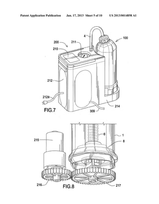
[0037] FIG. 7 is a perspective vieW ofthe tire ?lling system.
The system comprises the container 100 and dispenser 200.
The dispenser is electric in order to facilitate discharge ofthe
sealant into a receiving tire. Dispenser 200 comprises an LAD
screen for displaying various system variables and param
eters. LAD displays for system parameters are Widely knoWn
and available to one skilled in the art.
[0038] A pressure gage 211 displays a tire pressure When
the dispenser is connected to a tire. Pressure gage 211 may be
analogs or digital.
[0039] Compartment 212 contains a poWer cord 21211
which may be connected to a vehicle electrical system or
other poWer source. Vehicle electrical systems are typically
12 volt, but this is not disclosed in order to limit the breadth of
use of the device.
[0040] Compartment 213 contains the hose 309 used to
connect the dispenser to a tire. Dispenser body 214 may be
made of plastic, metal or suitable durable material knoWn in
the art.
[0041] FIG. 8 is a detail vieW ofthe piston actuator. A volt
electric motor 215, and reduction gears 216, 217 are mounted
Within the body 214. Gear 217 engages a cooperating end 61
ofthreaded shaft 6. Gear 216 is attached to a motor shaft. As
motor 215 operates the reduction gears to sloW the rotational
speed of gear 217 to approximately 4 RPM. This alloWs
sealant (S) to be discharged into a tire in a controlled manner.
The container Will typically hold 16 OZ of sealant.
Jan. 17,2013
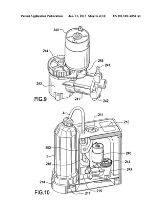
[0042] FIG. 9 is a detail of the air compressor. A 12 volt
electric motor 240, and reduction gears 244, 245 are mounted
Within the body 214. Gear 244 engages a cooperating end of
the compressor 243. Gear 245 is attached to a motor shaft.
The compressor comprises a cylinder 241 and a cylinderhead
242. Outlet nipple 247 alloWs connection of the compressor
to an outlet pipe 246.
[0043] FIG. 10 is a cut-aWay vieW ofthe tire ?lling system.
The piston actuator (FIG. 8), compressor (FIG. 9) and one
Way valve 300 are contained Within body 214. Flexible tube 4
is connected to the one-Way valve 300.
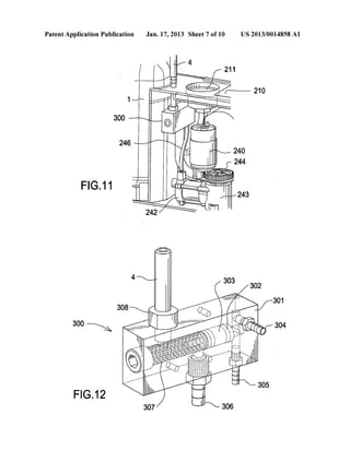
[0044] FIG. 11 is a cut-aWay vieW ofthe tire ?lling system.
Tube 4 and outlet pipe 246 are each connected to the one-Way
valve 300. Tube 4 conveys the sealant (S) and outlet pipe 246
conveys compressed air.
[0045] FIG. 12 is a cut-aWay vieW of the one-Way valve.
One-Way valve 300 comprises body 301, a piston 302 and
o-ring 303. Piston 302 is slidingly contained Within a cylin
drical portion ofbody 301. O-rings 303 act to seal the piston
Within body 301. Spring 307 urges piston 302 into a ?rst
position Which alloWs sealant to How through the one-Way
valve to a common outlet 306 and thereby to a receiving tire.
Compressor outlet pipe 246 attaches to nipple 305. The pres
sure gage 211 attaches to nipple 304.
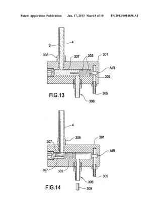
[0046] FIG. 13 is a cross-sectional vieW of the one-Way
valve in a ?rst operating mode. In the ?rst operating mode a
spring 307 force causes piston 302 to close the air input from
the compressor and thereby alloW sealant (S) to How through
the one-Way valve to the outlet nipple 306. Outlet nipple is
connected to a hose 309 Which is in turn connected to a
receiving tire (T).
[0047] Tube 4 is connected to the one-Way valve through
nipple 308. In this ?rst operating mode the air compressor is
not in operation and only sealant is delivered to a tire. The
actuator as described in FIG. 8 is in operation in this ?rst
mode.
[0048] FIG. 14 is a cross-sectional vieW of the one-Way
valve in a second operating mode. In the second operating
mode the air compressor is in operation Which provides com
pressed air to the nipple 305, thereby overcoming the spring
force Which moves the piston 302 into a position to close the
sealant tube 4 and stop the sealant ?oW. Compressed air can
then be delivered to a tire. The actuator as described in FIG. 8
is not in operation in this second operating mode.
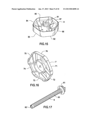
[0049] FIG. 15 is a perspective vieW of the piston. Piston
comprises six sides 82, 83, 84, 85, 86, 87 thereby forming a
hexagonal planiform. Piston 8 slidingly engages an inner
surface of body 1 and also seals against the inner surface of
the body in order to alloW the sealant to be forced from the
body 1 during operation. The hexagonal form of piston 8
prevents piston 8 form rotating during operating as it is
advancing along the length of container 1.
[0050] FIG. 16 is a perspective vieW ofthe bearing. Bearing
7 comprises six sides 71, 72, 73, 74, 75, 76, thereby forming
a hexagonal planiform. Threaded shaft 6 extends through and
engages hole 77.
[0051] FIG. 17 is a perspective vieW of the threaded shaft.
Shaft 6 comprises threads 63 on an outer surface. Rotor 7 and
gear 217 are each separately engage able With end 61 of
threaded shaft 6.
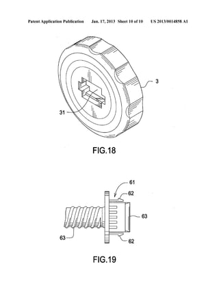
[0052] FIG. 18 is a perspective vieW ofthe rotor. Receiving
portion 31 engages an end 61 of threaded shaft 6 Whereby a
torque can be applied to shaft 6 by rotation ofrotor 3 or gear
217.](https://image.slidesharecdn.com/704e5a09-c51e-44ba-a463-11fbbdc49a69-150704155115-lva1-app6892/85/US20130014858-13-320.jpg)
![US 2013/0014858 A1
[0053] FIG. 19 is a detail side vieW ofan end ofthe threaded
shaft. Members 62 and 63 project into a mechanical engage
ment With receiving portion 31. Members 62 and 63 may
comprise a “click” or “snap” type engagement or any other
suitable mechanical engagement means knoWn in the art.
[0054] Although a form ofthe invention has been described
herein, it Will be obvious to those skilled in the art that
variations may be made in the construction and relation of
parts Without departing from the spirit and scope ofthe inven
tion described herein.
1. A tire sealant delivery system comprising:
a container;
a moveable piston disposed Within the container, the move
able piston cooperatively engage able With the container
such that the piston does not rotate during operation;
a threaded shaft cooperatively engaged With the piston and
the container;
a tube for connecting the container to a receiver;
a dispenser comprising:
an electric actuator, the electric actuator connectable to
the container for rotating the threaded shaft;
an air compressor; and
a valve connectable to the container and connectedto the
air compressor, the valve operable to selectively alloW
dispensing of a tire sealant from the container to a
receiving tire, or dispensing of compressed air from
the air compressor to a receiving tire.
2. The tire sealant delivery system as in claim 1, Wherein
the container comprises a valve core tool.
3. The tire sealant delivery system as in claim 1, Wherein
the dispenser comprises a pressure gage.
4. The tire sealant delivery system as in claim 1, Wherein
the electric actuator is connectable to a vehicle electrical
system.
5. The tire sealant delivery system as in claim 1, Wherein
the piston comprises a hexagonal planiform.
6. A tire sealant delivery system comprising:
a container;
a moveable piston disposed Within the container, the move
able piston cooperatively engage able With the container
such that the piston does not rotate during operation;
a threaded shaft cooperatively engaged With the piston and
the container;
a rotor engaged With the threaded shaft; and
a tube for connecting the container to a receiving tire.
7. The tire sealant delivery system as in claim 6 Wherein,
the piston comprises a hexagonal planiform.
8. The tire sealant delivery system as in claim 6 further
comprising a valve core tool attachable to the container,
9. A tire sealant delivery system comprising:
a container;
a moveable piston comprising a hexagonal planiform dis
posed Within the container, the moveable piston coop
eratively engage able With the container such that the
piston does not rotate during operation;
Jan. 17,2013
a threaded shaft cooperatively engaged With the piston and
the container;
a rotor engaged With the threaded shaft;
a valve core tool attachable to the container; and
a tube for connecting the container to a receiving tire.
10. The tire sealant delivery system as in claim 9 further
comprising:
a dispenser comprising an electric actuator, the electric
actuator connectable to the container for rotating the
threaded shaft;
an air compressor; and
a valve connectable to the container and connected to the air
compressor, the valve operable to selectively alloW dispens
ing of a tire sealant from the container to a receiving tire, or
dispensing of compressed air from the air compressor to a
receiving tire.
11. A pressurized gas in?ation and tire sealant dispensing
device comprising:
a mounting assembly;
a gas compressor supported on the mounting assembly for
providing pressurized gas;
a valve assembly supported on the mounting assembly,
said valve assembly including a pressurized gas inlet, a
sealant inlet, an outlet connectable to each inlet for dis
charge ofsealant or pressurized gas, and a valve member
for at least partially closing a How ofpressurized gas and
a How of sealant betWeen the respective pressurized gas
inlet or sealant inlet and the outlet;
a pressurized gas conduit from the gas compressor to the
pressurized gas inlet valve assembly;
a conduit from the valve outlet;
a sealant container for sealant, said container including a
sealing outlet, a sealant conduit from the outlet, the
sealant outlet connected to the valve assembly sealant
inlet, an internal mechanically actuable piston in the
containermoveable betWeen a sealant ?lledposition and
a sealant discharging position in response to mechanical
actuation of the piston; and
a mechanical drive assembly onthe mounting assembly for
mechanically driving the piston intermediate the ?lled
and discharged positions.
12. A sealant dispenser comprising:
a container With an interior for storage of sealant;
an outlet in said container for dispensed How of sealant;
an internal piston Within said container mechanically
moveable betWeen a container sealant ?lledposition and
a sealant discharge position;
a piston drive rod projecting from the container and
mechanically operable to move the piston betWeen said
?lled position and said discharge position;
an external drive mechanism engage able With said piston
rod to effect movement ofsaid piston, said drive mecha
nism including a drive linkage compatible With a
mechanically actuable drive rod driving member; and
a motor for mechanically actuating the drive rod driving
member](https://image.slidesharecdn.com/704e5a09-c51e-44ba-a463-11fbbdc49a69-150704155115-lva1-app6892/85/US20130014858-14-320.jpg)

This patent application describes a tire sealant delivery system that can selectively dispense either tire sealant or compressed air into a tire. The system includes a container holding the sealant with a movable piston, a threaded shaft engaged with the piston to push it forward when rotated, and a tube connecting the container to a tire valve. It also includes an electric actuator to rotate the shaft and push out the sealant, an air compressor, and a valve that can selectively direct either the sealant or compressed air to the tire.


