SlideShare a Scribd company logo
1 of 15
Download to read offline
(19)
US 20130146011A1
(12) Patent Application Publication (10) Pub. No.: US 2013/0146011 A1
United States
Agaram et al. (43) Pub. Date: Jun. 13, 2013
(54)
(71)
(72)
(21)
(22)
(60)
(51)
IGNITION MODULE
ApplicantszVenkatesh Agaram, Bloom?eld, MI
(US); Stefan HertWeck, Bloom?eld, MI
(US)
Inventors: Venkatesh Agaram, Bloom?eld, MI
(US); Stefan HertWeck, Bloom?eld, MI
(US)
Appl. No.: 13/675,001
Filed: Nov. 13, 2012
Related US. Application Data
Provisional application No. 61/569,003, ?led on Dec.
9, 201 1 .
Publication Classi?cation
Int. Cl.
F02N 99/00 (2006.01)
OFF
42
ACCESSORY 56
26
ON/RUN
IGNITION
76
(52) US. Cl.
CPC .................................... .. F02N 99/00 (2013.01)
USPC ..................................................... .. 123/1791
(57) ABSTRACT
An ignition module includes a housing, a cam, a ?rst lever, a
second lever, and an electromagnet is provided. The cam is
rotatably supported by saidhousing betWeen an OFF position
and an ON position. The ?rst lever is movable betWeen a ?rst
state restricting movement ofsaid cam from said ON position
to said OFF position and a second state permitting movement
of said cam from said ON position to said OFF position. The
second lever is movable betWeen a locked state restricting
movement ofsaid ?rst lever from said ?rst state to said second
state and an unlocked state permitting movement of said ?rst
lever from said ?rst state to said second state. The electro
magnet is movable betWeen an extended state and a retracted
state. The electromagnet movable into said extended state
When energized to position and maintain said second lever in
said locked state.
f12
Patent Application Publication Jun. 13, 2013 Sheet 1 0f 5 US 2013/0146011 A1
ACCESSORY
ON/RUN
Patent Application Publication Jun. 13, 2013 Sheet 2 0f 5 US 2013/0146011 A1
[Fig-4
Patent Application Publication Jun. 13, 2013 Sheet 3 0f 5 US 2013/0146011 A1
Patent Application Publication Jun. 13, 2013 Sheet 4 0f 5 US 2013/0146011 A1
84
Engine Stopped f
Passive Electromagnet fsa
96_—P'E|t t I A'Elt tasslve ecromagne ctlve ecromagne 94
Ignition "OFF“ Position fgo
[Fig-7
42a 40a 54 60a 52a
76 58 Fig -8
Patent Application Publication Jun. 13, 2013 Sheet 5 0f 5 US 2013/0146011 A1
US 2013/0146011A1
IGNITION MODULE
CROSS-REFERENCE TO RELATED
APPLICATION
[0001] This application claims the bene?t of US. Provi
sional Ser. No. 61/569,003, ?led Dec. 9, 2011.
FIELD
[0002] The present disclosure relates to ignition modules
and more particularly to an ignition module having a release
feature permitting removal of a key fob from the ignition
module under insu?icient poWer conditions.
BACKGROUND
[0003] Ignition modules are typically incorporated into a
vehicle to permit a driver to selectively control the vehicle
from an OFF state to an ON state. Such ignition modules
typically include a receptacle that receives a key and/or key
fob that, When rotated or depressed, moves the vehicle from
the OFF state to the ON state. The key and/or key fob is
typically retained Within the ignition When the vehicle is in
the ON state to prevent removal ofthe key and/orkey fob from
the ignition during use. Once the vehicle is returned to a
parked state and the key and/or key fob is returned to an OFF
position, the key and/or key fob may be removed from the
ignition module.
[0004] Vehicle manufacturers have recently incorporated
the function ofa conventional key and a conventional key fob
into a single unit in a continuing effort to simplify operation
and use ofvehicles. Speci?cally, a vehicle may incorporate a
Wireless ignition module that interfaces With a key fob With
out the need for a conventional key. The key fob functions in
a conventional manner in that a user may unlock and lock
vehicle doors and may open other access compartments ofthe
vehicle (i.e., a trunkor sliding door) but, also, incorporates the
functionality ofa conventional key. Namely, the key fob may
be inserted into the Wireless ignition module and may com
municate With the Wireless ignition module When depressed
orrotatedto control the vehicle betWeen the OFF state and the
ON state.
[0005] A key fob used in conjunction With a Wireless igni
tion module is prevented from being removed from the igni
tion While the vehicle is in the ON state and the vehicle is not
in the parked state. The fob is only permitted to be removed
from the ignition module once the vehicle is returned to the
parked state and the fob is returned to the OFF position.
[0006] Conventional Wireless ignition modules typically
incorporate a solenoid that Works in conjunction With a series
of linkages to prevent removal of the fob from the ignition
module until the vehicle is returned to the OFF state and the
fob is returned to the OFF position. At this point, the solenoid
may be energiZed to actuate the series of linkages and permit
removal of the fob from the ignition module.
[0007] While conventional ignition modules adequately
maintain engagement of the fob and the ignition module
When the vehicle is in the ON state and adequately permit
removal ofthe fob from the ignition module When the vehicle
is returned to the OFF state, such ignition modules do not
permit removal ofthe fob from the ignition module When the
vehicle is incapable of providing su?icient poWer to actuate
the solenoid. For example, When a battery of the vehicle is
dead, poWer cannot be supplied to the solenoid to actuate the
linkages and permit removal of the fob from the module.
Jun. 13,2013
Under such circumstances, the fob remains locked in the
ignition module and cannot be removed until poWer is
restored to the vehicle.
SUMMARY
[0008] An ignition module is provided and may include a
housing and a cam rotatably supported by the housing
betWeen an OFF position and an ON position. A ?rst lever
may be movable betWeen a ?rst state restricting movement of
the cam from the ON position to the OFF position and a
second state permitting movement of the cam from the ON
position to the OFF position. A second lever may be movable
betWeen a locked state restricting movement ofthe ?rst lever
from the ?rst state to the second state and an unlocked state
permitting movement of the ?rst lever from the ?rst state to
the second state. An electromagnet may be movable betWeen
an extended state and a retracted state and may be movable
into the extended state When energiZed to position and main
tain the second lever in the locked state.
[0009] In another con?guration, an ignition module for a
vehicle having an energy source is provided and may include
a housing and a cam rotatably supported by the housing
betWeen an OFF position and an ON position. A ?rst lever
may be movable betWeen a ?rst state restricting movement of
the cam from the ON position to the OFF position and a
second state permitting movement of the cam from the ON
position to the OFF position. A second lever may be movable
betWeen a locked state restricting movement ofthe ?rst lever
from the ?rst state to the second state and an unlocked state
permitting movement of the ?rst lever from the ?rst state to
the second state. An electromagnet movable betWeen an
extended state and a retracted state may be movable into the
extended state to position and maintain the second lever in the
locked state. A release mechanism may permit movement of
the cam from the ON position to the OFF position When
poWer from the energy source is insuf?cient to move the
electromagnet betWeen the extended state and the retracted
state.
[0010] Further areas of applicability of the present inven
tion Will become apparent from the detailed description pro
vided hereinafter. It should be understood that the detailed
description and speci?c examples, While indicating the pre
ferred embodiment ofthe invention, are intended forpurposes
of illustration only and are not intended to limit the scope of
the invention.
BRIEF DESCRIPTION OF THE DRAWINGS
[0011] The present invention Will become more fully
understood from the detailed description and the accompa
nying draWings, Wherein:
[0012] FIG. 1 is a partial perspective vieW of a passenger
compartment ofa vehicle incorporating an ignition module in
accordance With the principles ofthe present disclosure;
[0013] FIG. 2 is a partial front vieW ofan ignition module in
accordance With the principles ofthe present disclosure;
[0014] FIG. 3 is a partial rearvieW ofthe ignition module of
FIG. 2 shoWn in an OFF state;
[0015] FIG. 4 is a partial rearvieW ofthe ignition module of
FIG. 2 shoWn in an accessory position betWeen an OFF posi
tion and an ON position;
[0016] FIG. 5 is a partial rearvieW ofthe ignition module of
FIG. 2 shoWn in an ON position;
US 2013/0146011Al
[0017] FIG. 6 is a partial rearvieW ofthe ignition module of
FIG. 2 shown in an OFF position;
[0018] FIG. 7 is a ?owchart detailing operation ofthe igni
tion module of FIG. 2;
[0019] FIG. 8 is a partial rear vieW ofan ignition module in
accordance With the principles ofthe present disclosure;
[0020] FIG. 9 is a partial rear vieW ofan ignition module in
accordance With the principles ofthe present disclosure; and
[0021] FIG. 10 is a partial rear vieW of an ignition module
in accordance With the principles of the present disclosure.
DETAILED DESCRIPTION
[0022] The folloWing description ofthe preferred embodi
ments is merely exemplary innature and is inno Way intended
to limit the invention, its application, or uses.
[0023] With reference to the ?gures, a vehicle 10 is pro
vided and may include an ignition module 12. The ignition
module 12 may be associated With a steering column 14 and
steering Wheel 16 of the vehicle 10 such that the ignition
module 12 is a subassembly ofthe steering column 14 and is
positioned in close proximity to the steering Wheel 16. While
the ignition module 12 is described and shoWn as being asso
ciatedWith a steering column 14 ofthe vehicle 10, the ignition
module 10 could be located anyWhere Within a passenger
compartment 18 of the vehicle 10. For example, the ignition
module 12 could be located in an instrument panel 20 of the
vehicle 10.
[0024] The ignition module 12 may be a Wireless ignition
module that selectively receives a key fob (not shoWn) for use
in controlling the vehicle 10 betWeen an ON state and an OFF
state and for supplying poWer to various subsystems of the
vehicle 10. For example, the key fob may be used to position
the ignition module 12 and, thus, the vehicle 10, in an
ACCESSORY state (FIG. 4), that supplies poWer to vehicle
accessories such as, for example, a radio 15 or other vehicle
instruments 17 but does not change an operating state of the
vehicle 10 from the OFF state to the ON state.
[0025] The key fob may be an integratedkey fob that alloWs
for operation of various subsystems of the vehicle 10 While
concurrently alloWing an operator to control the vehicle 10
betWeen the OFF state, the ON state, and the ACCESSORY
state. For example, the key fob may permit an operatorto lock
and unlock vehicle doors 19, open and close rear or side
closure panels depending on the particular vehicle, and/or
initiate an alarm function ofthe vehicle 10. The key fob may
additionally include an integrated key such that When the key
fob is received by the ignition module 12, the key fob alloWs
the user to manipulate the ignition module 12 and, thus, the
vehicle 10, betWeen the OFF state, the ON state, and the
ACCESSORY state.
[0026] The ignition module 12 is described as being a Wire
less ignition module, as the ignition module Wirelessly com
municates With the key fob to properly identify the key fob
Whenreceivedby the ignitionmodule 12. Further, the ignition
module 12 may control operation of the vehicle 10 amongst
the ON state, the OFF state, and the ACCESSORY state by
Wirelessly communicatingWith abody controller (not shoWn)
ofthe vehicle 10, for example, Whenthekey fob is receivedby
the ignition module 12. The ignition module 12 may include
a processor and memory (neither shoWn) for accomplishing
Wireless communication betWeen the ignition module 12 and
the key fob and for accomplishing Wireless communication
betWeen the ignition module and the body controller.
Jun. 13,2013
[0027] During operation, the ignition module 12 may
receive the key fob and may ?rst identify the key fob. If the
correct key fob is received by the ignition module 12, the
ignition module 12 may alloW an operator to utiliZe the key
fob and control the vehicle 10. If, hoWever, an incorrect key
fob is received by the ignition module 12, the ignitionmodule
12 may identify the incorrect key fob and Will not permit an
operator to control the vehicle 10.
[0028] Once the ignition module 12 receives and identi?es
the correct key fob, a force may be applied to the key fob to
control operation ofthe vehicle 10. For example, the key fob
may be rotated into various positions to control an operating
state of the vehicle 10. Namely, the key fob may be ?rst
rotated from an OFF position to an ACCESSORY position
that alloWs an operator to control various subassemblies or
accessories ofthe vehicle 10. The key fob may additionally be
rotated from theACCESSORY position past the ON position
to an IGNITE position in an effort to start an engine (not
shoWn) ofthe vehicle 10. Once the engine is started, the key
fob may be automatically rotated from the IGNITE position
to the ON position When the vehicle 10 is running. Again,
because the ignition module 12 may be a Wireless ignition
module, When a force is appliedto the key fob to rotate the key
fob from the OFF position to the ACCESSORY position,
IGNITE position, or ON position, the control module 12 may
sense a rotational position of the key fob and may relay the
rotational position of the key fob to the body controller to
alloW the body controller to properly control the vehicle 10
based on the detected position of the key fob. For example,
When the key fob is initially rotated from the OFF position to
the IGNITE position, the ignition module 12 identi?es the
change in the rotational position from the OFF position to the
IGNITE position ofthe key fob and relays the information to
the body controller. The body controller may rely on such
information in controlling the engine of the vehicle 10 and
may cause the engine to start.
[0029] During the foregoing operation, removal ofthe key
fob from the ignition module 12 is typically restricted until
the vehicle 10 is in a parked state and the key fob is returned
to the OFF position. As Will be described in greater detail
beloW, the ignition module 12 restricts removal ofthe key fob
until the vehicle 10 is moved into a parked state and the key
fob is rotated into the OFF position. The ignition module 12
additionally permits removal ofthe key fob under conditions
When insuf?cient poWer is supplied from the vehicle 10 to the
ignition module 12.
[0030] With particular reference to FIGS. 2-6, the ignition
module 12 is shoWn to include a housing 22 and a cylinder 24
rotatably supported by the housing 22. The housing 22 may
include a series ofattachment features 26 that may be used to
assemble the ignition module 12 to the steering column 14 or
instrument panel 20. The attachment features 26 may position
the ignition module 12 relative to and Within the steering
column 14 or instrument panel 20 to alloW a portion of the
cylinder 24 to be exposed (FIG. 1).
[0031] The cylinder 24 is rotatably supported by the hous
ing 22 suchthat a ?rst end 28 (FIG. 2) extends from a ?rst side
ofthe housing 22 (FIG. 2) and a second end 30 ofthe cylinder
24 extends from an opposite side of the housing 22 (FIGS.
3-6). The ?rst end 28 may include a receptacle 32 that selec
tively receives the key fob. When the key fob is received
Within the receptacle 32, a force may be applied to the key fob
to rotate the key fob and the cylinder 24 relative to the housing
22. As described above, the key fob may be in Wireless com
US 2013/0146011Al
munication With the ignition module 12 and, as a result, a
rotational position of the cylinder 24 and, thus, the key fob
relative to the housing 22, may be detected by the ignition
module 12 and reported to the vehicle controller.
[0032] The second end 30 of the cylinder 24 extends from
an opposite side of the housing 22 than the ?rst end 28. The
second end 30 may include a cam surface 34 as Well as a guide
36 de?ned by Walls 38 extending from the cylinder 24.
[0033] With continued reference to FIGS. 2 and 3, the cyl
inder 24 is shoWn as being rotatable betWeen an OFF position,
an ACCESSORY position, an ON/RUN position, and an
IGNITE position relative to the housing 22. The various posi
tions of the cylinder 24 relative to the housing 22 may be
accomplished When a key fob is inserted into the receptacle
32 ofthe cylinder 24 and the key fob is rotated relative to the
housing 22.
[0034] When the key fob is received in the receptacle 32 of
the cylinder 24, the ignition module 12 ?rst identi?es the key
fob. Ifthe correct key fob is inserted in the receptacle 32, the
ignition module 12ivia the body controlleripermits a user
to control the vehicle 10 and vehicle subsystems by simply
applying a rotational force to the cylinder 24 via the key fob
to rotate the cylinder 24 betWeen the various positions shoWn
in FIGS. 2 and 3. If, on the other hand, an incorrect key fob is
inserted into the receptacle 32 ofthe cylinder 24, the ignition
module 24 may identify the key fob as being an incorrect key
fob. Upon identifying an incorrect key fob, the ignition mod
ule 12 may Wirelessly communicate a signal to the body
controller, for example, instructing the body controller to
prevent operation ofthe vehicle 10 and any accessories ofthe
vehicle 10. Speci?cally, While the key fob and cylinder 24
may be permitted to rotate relative to the housing 22, the
ignition module 22 may prevent operation of the vehicle 10
and any vehicle accessories by communicating to the body
controller that an incorrect key fob is received in the ignition
module 12.
[0035] With particular reference to FIGS. 2 and 6, the igni
tionmodule 12 is shoWn as including a locking mechanism 40
that selectively prevents rotation ofthe cylinder 24 relative to
the housing 22 to prevent inadvertent removal ofthe key fob
from the receptacle 32 When the vehicle 10 is in the RUN
state, the ACCESSORY state, or the IGNITE state. The lock
ing mechanism 40 may include a locking member 42, a lever
44, an electromagnet 46, and a biasing member 48. The lock
ing member 42 may include a ?rst engagement surface 50 and
a second engagement surface 52 in selective engagement With
the lever 44. The locking member 42 may be rotatably sup
ported by the housing 22 by a pivot 54 and may be biased in
the counterclockWise direction relative to the vieW shoWn in
FIG. 3 by a biasing member 56.
[0036] The lever 44 may be pivotably supported by the
housing 22 by a pivot 58 to permit the lever 44 to move
relative to the housing 22 When the cylinder 24 is moved
betWeen the OFF state, theACCESSORY state, the ON/RUN
state, and the IGNITE state (FIGS. 2 and 3). The lever 44 may
include a ?rst engagement surface 60, a second engagement
surface 62, an extension 64, a cam folloWer 66, and a shoulder
68. The ?rst engagement surface 60 may be in selective con
tact With the ?rst engagement surface 50 ofthe locking mem
ber 42 While the second engagement surface 62 may be in
selective contact With the second engagement surface 52 of
the locking member 42. The extension 64 may be slidably
received Within the guide 36 of the cylinder 24 When the
cylinder 24 is rotated relative to the housing 22. The cam
Jun. 13,2013
folloWer 66 may be disposed proximate to the extension 64
and may contact the cylinder 24 When the cylinder 24 is
rotated from the OFF position to any of the ACCESSORY
position, the ON/RUN position, or the IGNITE position. The
shoulder 68 may extend generally from the lever 44 and may
be in contact With the biasing member 48 to alloW the biasing
member 48 to apply a force to the lever 44.
[0037] Electromagnet 46 may be supported by the housing
22 and may include an output shaft 70 and a Wound core 72.
The output shaft 70 may be moved betWeen an extended state
(FIGS. 3-5) and a retracted state (FIG. 6) by selectively sup
plying current to the Wound core 72 ofthe electromagnet 46.
The current may be supplied to the Wound core 72 at one or
more terminals 74 that are in electrical communication With
the Wound core 72.
[0038] The biasing member 48 may be received Within a
seat 76 of the housing 22 to alloW attachment of the biasing
member 48 to the housing 22. The biasing member 48 may
include a spring or other biasing element (not shoWn) that
exerts a force on the shoulder 68 ofthe lever 44 in a direction
W. The force exerted on the lever 44 at the shoulder 68 causes
the lever 44 to be biased in the clockWise direction relative to
the vieWs shoWn in FIGS. 3-5.
[0039] With particular reference to FIGS. 2-6, operation of
the ignition module 12 Will be described in detail. When the
vehicle 10 is initially at rest, the ignition module 12 is in the
OFF position (FIGS. 2 and 3). The ignitionmodule 12 may be
biased into the OFF position by a biasing element 78 that
applies a force to the cylinder 24, thereby causingthe cylinder
24 to be biased in the clockWise direction relative to the vieWs
shoWn in FIGS. 3-5.
[0040] A key fob may be inserted into the receptacle 32 to
alloW an operator to rotate the cylinder 24 relative to the
housing 22. When the key fob is initially received in the
receptacle 32, the ignition module 12 may ?rst identify the
key fob via Wireless communication. If the key fob is not
identi?ed or is identi?ed as being an incorrect key fob, the
ignition module 12 may permit rotation of the key fob and
cylinder 24 relative to the housing 22 but Will send a signal to
the body controller ofthe vehicle 10, for example, to prevent
use of the vehicle 10 and any vehicle accessories. If, on the
otherhand, the ignition module 12 recogniZes the key fob, the
ignition module 12 Will permit the user to not only rotate the
key fob and cylinder 24 relative to the housing 22 but, also,
Will permit use ofthe vehicle 10 and any vehicle accessories
by sending a signal to the body controller that the correct key
is disposed Within the receptacle 32.
[0041] A force may be applied to the cylinder 24 to rotate
the cylinder 24 relative to the housing 22 by applying a
rotational force to the key fob. When the cylinder 24 is ini
tially rotated relative to the housing 22, the cylinder 24 is
rotated from the OFF position to the ACCESSORY position.
At this point, the electromagnet 46 is energiZed, thereby
causing the output shaft 70 ofthe electromagnet 46 to extend
from the Wound core 72 and apply a force on the locking
member 42. The force applied to the locking member 42
causes the locking member 42 to rotate in the clockWise
direction relative to the vieWs shoWn in FIGS. 3-5 about the
pivot 54.
[0042] When the cylinder 24 is suf?ciently rotated in the
counterclockWise direction relative to the vieWs shoWn in
FIGS. 3-5 from the OFF position to the ACCESSORY posi
tion, the cam folloWer 66 ofthe lever 44 disengages the cam
surface 34 of the cylinder 24 and, as a result, permits the
US 2013/0146011A1
biasing member 48 to rotate the lever 44 in the clockwise
direction relative to the views shown in FIGS. 3-5 about the
pivot 58.
[0043] Whenthe lever 44 is suf?ciently rotated inthe clock
wise direction relative to the views shown in FIGS. 3-5, the
?rst engagement surface 50 ofthe locking member 42 disen
gages the ?rst engagement surface 60 ofthe lever 44, thereby
allowing the output shaft 70 ofthe electromagnet 46 to rotate
the locking member 42 about the pivot 54 clockwise such that
the second engagement surface 52 ofthe locking member 42
contacts the second engagement surface 62 of the lever 44
(FIG. 4). At this point, the cylinder 24 is in the accessory
position and the extension 64 and cam follower 66 ofthe lever
44 are in contact with the wall 38 ofthe cylinder 24, with the
extension 64 being at least partially received within the guide
36. When the ignition module 12 is in the ACCESSORY
position, the ignition module 12 may send a signal to the body
controller, instructing the body controllerto provide powerto
the accessories of the vehicle 10 to allow the operator to use
the various accessories of the vehicle 10.
[0044] When the cylinder 24 is in the ACCESSORY posi
tion, such that the locking member 42 is permitted to rotate in
the clockwise direction relative to the views shown in FIGS.
3-5, the second engagement surface 52 ofthe locking member
42 may contact the second engagement surface 62 ofthe lever
44 to prevent rotation ofthe lever 44 about the pivot 58 in the
counterclockwise direction relative to the views shown in
FIGS. 3-5. Preventing rotation of the lever 44 relative to the
housing 22 in the counterclockwise direction relative to the
views shown in FIGS. 3-5 prevents the cylinder 24 from
returning to the OFF position and, thus, prevents removal of
the key fob from the receptacle 32. Speci?cally, the key fob
may only be removed from the receptacle 32 of the cylinder
24 when the cylinder 24 is in the OFF position. Therefore, if
the cylinder 24 is prevented from returning to the OFF posi
tion due to engagement between the locking member 42 and
the lever 44, the key fob will remain within the receptacle 32
and is prevented from being removed from the cylinder 24
when the cylinder 24 is in the ACCESSORY position.
[0045] If the force applied to the key fob is released when
the cylinder 24 is intheACCESSORY position, the engine of
the vehicle 10 remains offwhile accessories ofthe vehicle 10
may be used. Again, the ignition module 12 may communi
cate with the body controller to instruct the body controller to
provide power to the accessories of the vehicle 10 when the
cylinder 24 is in the ACCESSORY position. The ignition
module 12 may identifytheACCESSORYpositionby detect
ing a rotational position of the cylinder 24 relative to the
housing 22. The ignition module 12 will remain in the
ACCESSORY position until a force is applied to the cylinder
24 via the key fob to either return the cylinder 24 to the OFF
position or to advance the cylinder 24 in the opposite rota
tional direction into the IGNITE position and, ?nally, into the
ON/RUN position.
[0046] If a rotational force is applied to the cylinder 24 via
the key fob such that the cylinder 24 is returned to the OFF
positionfromtheACCESSORYposition, the ignitionmodule
12 identi?es the rotational movement ofthe cylinder 24 rela
tive to the housing 22 and instructs the electromagnet 46 to
retract the output shaft 70 into the wound core 72 to allow the
locking member 42 to rotate in the counterclockwise direc
tion relative to the views shown in FIGS. 3-5 such that the
second engagement surface 52 of the locking member 42
disengages the second engagement surface 62 ofthe lever 44.
Jun. 13,2013
The locking member 42 is rotated in the counterclockwise
direction relative to the views shown in FIGS. 3-5 by the
biasing member 56 disposed generally between the locking
member 42 and the electromagnet 46. Therefore, when cur
rent is restricted from ?owing to the electromagnet 46, the
output shaft 70 retracts into the wound core 72, thereby allow
ing the biasing member 56 to rotate the locking member 42 in
the counterclockwise direction relative to the views shown in
FIGS. 3-5 and out of engagement with the lever 44.
[0047] When the locking member 42 is disengaged from
the lever 44, a rotational force applied to the cylinder 24 at the
key fob causes the cam surface 34 ofthe cylinder 24 to engage
the cam follower 66 ofthe lever 44 to rotate the lever 44 in the
counterclockwise direction relative to the views shown in
FIGS. 3-5 about the pivot 58 and against the biasing force
exerted on the shoulder 68 of the lever 44 by the biasing
member 48. In other words, permitting rotation ofthe lever 44
in the counterclockwise direction relative to the views shown
in FIGS. 3-5 permits the cylinder 24 to be rotated from the
ACCESSORY position to the OFF position.
[0048] Ifthe force applied to the cylinder 24 via the key fob
rotates the cylinder 24 from the ACCESSORY position to the
IGNITE position, the extension 64 and cam follower 66 ofthe
lever 44 ride along an outer surface 80 ofthe wall 38 andmove
further into the guide 36. The guide 36 may include a stop 82
that restricts rotation of the cylinder 24 in the counterclock
wise direction relative to the views shown in FIGS. 3-5 past
the IGNITE position. For example, as the cylinder 24 is
rotated from the ACCESSORY position to the IGNITE posi
tion and the extension 64 of the lever 44 moves within the
guide 36 toward the stop 82, the extension 64 will eventually
contact the stop 82, thereby preventing further rotation ofthe
cylinder 24 in the counterclockwise direction relative to the
views shown in FIGS. 3-5.
[0049] When the cylinder 24 is rotated from the ACCES
SORY position to the IGNITE position, the second engage
ment surface 52 ofthe locking member 42 maintains engage
ment with the second engagement surface 62 ofthe lever 44 to
prevent rotation of the lever 44 about the pivot 58 in the
counterclockwise direction relative to the views shown in
FIGS. 3-5. As described above, preventing rotation of the
lever 44 in the counterclockwise direction relative to the
views shown in FIGS. 3-5 prevents removal of the key fob
from the receptacle 32 when the cylinder 24 is in any of the
ACCESSORY position, the ON/RUN position, or the
IGNITE position. Once the cylinder 24 reaches the IGNITE
position, the force applied to the key fob may be released.
Releasing the force applied to the key fob allows the biasing
element 78 to rotate the cylinder 24 in the clockwise direction
relative to the views shown in FIGS. 3-5 to move the cylinder
24 from the IGNITE position to the ON/RUN position.
[0050] The cylinder 24 is permitted to rotate from the
IGNITE position to the ON/RUN position and in the clock
wise direction relative to the view shown in FIG. 3, as the cam
follower 66 is permitted to move along the surface 80 of the
cylinder 24 between the ACCESSORY position, the
ON/RUN position, and the IGNITE position without apply
ing a force on the lever 44. Speci?cally, the surface 80 is
substantially constant and, as a result, does not apply a force
on the lever 44 at the cam follower 66 when the cylinder 24 is
rotated relative to the lever 44 between the ACCESSORY
position, the ON/RUN position, and the IGNITE position, as
the cam follower 66 simply traverses the constant surface 80
when the cylinder 24 is rotated relative to the housing 22
US 2013/0146011A1
between the various positions. Further rotation ofthe cylinder
24 into the OFF position is prevented, as the cam follower 66
would necessarily disengage surface 80 and engage cam sur
face 34, thereby causing a force to be applied to the lever 44.
The applied force urges the lever 44 to rotate about pivot 58 in
the counterclockwise direction relative to the view shown in
FIG. 3. However, the lever 44 is prevented from rotating in the
counterclockwise direction relative to the view shown in FIG.
3 until the electromagnet 46 is de-energiZed and the locking
member 42 is disengaged from the lever 44.
[0051] At this point, the ignition module 12 detects the
rotational position ofthe cylinder 24 relative to the housing 22
and identi?es the position to the body controller, for example.
The body controller, upon receiving the position of the cyl
inder 24, causes the engine to start when the cylinder 24 is in
the IGNITE position and continues operation ofthe engine of
the vehicle 10 when the cylinder 24 is in the ON/RUN posi
tion.
[0052] The engine of the vehicle 10 will continue to run,
provided the cylinder 24 is maintained in the ON/RUN posi
tion. However, when a force is applied to the cylinder 24 to
rotate the cylinder 24 in the clockwise direction relative to the
views shown in FIGS. 3-5, the cylinder 24 is rotated from the
ON/RUN position toward the ACCESSORY position and
OFF position. When the cylinder 24 reaches the OFF posi
tion, the ignition module 12 identi?es the position of the
cylinder 24 relative to the housing 22 and stops the supply of
current provided to the electromagnet 46. Restricting current
to the electromagnet 46 causes the output shaft 70 to retract
into the wound core 72. Retraction of the output shaft 70
allows the biasing member 56 to exert a force on the locking
member 42 and rotate the locking member 42 about the pivot
54 in the counterclockwise direction relative to the views
shown in FIGS. 3-5.
[0053] Upon suf?cientrotation ofthe lockingmember42 in
the counterclockwise direction relative to the views shown in
FIGS. 3-5, the second engagement surface 52 of the locking
member 42 disengages the second engagement surface 62 of
the lever 44, thereby allowing the lever 44 to be rotated in the
counterclockwise direction relative to the views shown in
FIGS. 3-5. The lever 44 is caused to rotate in the counter
clockwise direction relative to the views shown in FIGS. 3-5
due to engagement between the extension 64 and cam fol
lower 66 with the cam surface 34 of the cylinder 24. The
extension 64 and cam follower 66 engage the cam surface 34
when the cylinder 24 is suf?ciently rotated in the clockwise
direction relative to the views shown in FIGS. 3-5. Rotation of
the lever 44 in the counterclockwise direction relative to the
views shown in FIGS. 3-5 about the pivot 58 causes the lever
44 to move against the force exerted on the shoulder 68 ofthe
lever 44 by the biasing member 48.
[0054] When the cylinder 24 is returned to the OFF posi
tion, the ?rst engagement surface 50 of the locking member
42 may be in contact with the ?rst engagement surface 60 of
the lever 44. The lever 44 may be maintained in the position
shown in FIG. 6 due to engagement between the cam follower
66 of the lever 44 and the cam surface 34 of the cylinder 24.
At this point, a force may be exerted on the key fob to remove
the key fob from the receptacle 32 as the cylinder 24 is
returned to the OFF position.
[0055] As described above, when current is supplied to the
electromagnet 46, the output shaft 70 extends from the wound
core 72 and prevents the biasing member 56 from rotating the
locking member 42 in the counterclockwise direction relative
Jun. 13,2013
to the views shown in FIGS. 3-5.As such, the locking member
42 is positioned to engage the lever 44 when the cylinder 24
is rotated in the counterclockwise direction relative to the
views shown in FIGS. 3-5 to prevent the lever 44 from rotat
ing in the counterclockwise direction relative to the views
shown in FIGS. 3-5 in an effort to prevent removal ofthe key
fob from the receptacle 32 ofthe cylinder 24 when the cylin
der 24 is in any of the ACCESSORY position, the ON/RUN
position, or the IGNITE position. In short, when the cylinder
24 is moved into any of the ACCESSORY position, the
ON/RUN position, or the IGNITE position, current is con
tinually supplied to the electromagnet 46 to ensure that the
output shaft 70 extends from the wound core 72 and prevents
rotation of the locking member 42 in the counterclockwise
direction relative to the views shown in FIGS. 3-5.
[0056] Should the vehicle 10 experience a power failure
such as, for example, a dead battery during use, the current
supplied to the electromagnet 46 will cease. Therefore, the
output shaft 70 will automatically move into the wound core
72 and the biasing member 56 will be permitted to apply a
force on the locking member 42 to rotate the locking member
42 in the counterclockwise direction relative to the views
shown in FIGS. 3-5. As described above, permitting rotation
of the locking member 42 in the counterclockwise direction
relative to the views shown in FIGS. 3-5 permits the lever 44
to likewise be rotated in the counterclockwise direction rela
tive to the views shown in FIGS. 3-5 when the cylinder 24 is
rotated in the clockwise direction relative to the views shown
in FIGS. 3-5. Suf?cient rotation of the cylinder 24 in the
clockwise direction relative to the views shown in FIGS. 3-5
allows the cylinder 24 to be moved into the OFF position,
which allows an operator to apply a force on the key fob to
remove the key fob from the receptacle 32. Therefore, even
when the vehicle 10 experiences a power outage, an operator
is permitted to remove the key fob from the ignition module
12.
[0057] With particular reference to FIG. 7, a ?owchart is
providedthat summarizes the foregoing operation ofthe igni
tion module 12. Namely, the ignition module 12 will detect
that the engine is stopped at 84. The ignition module 12 will
then determine whether the vehicle 10 is in the parked posi
tion at 86. If the vehicle 10 is in the parked position at 86,
current will not be supplied to the electromagnet 46, thereby
resulting in the electromagnet 46 being a so-called “passive”
electromagnet 46 at 88. When the electromagnet 46 is not
supplied with current, the cylinder 24 may be moved into the
OFF position at 90 and the key fob may be removed from the
ignition module 12, as previously described.
[0058] Ifthe vehicle 10 is not in the parked position at 86,
the ignitionmodule 12 will then determine whether the power
source of the vehicle 10 is alive at 92. Ifthe power source of
the vehicle 10 is determined to be alive at 92, the ignition
module 12 will supply the electromagnet 46 with current at 94
to prevent the biasing member 56 from rotating the locking
member 42 in the counterclockwise direction relative to the
views shown in FIGS. 3-5. As described above, preventing the
locking member 42 from rotating in the counterclockwise
direction relative to the views shown in FIGS. 3-5 after the
cylinder 24 is moved into any ofthe ACCESSORY position,
the ON/RUN position, or the IGNITE position prevents the
cylinder 24 from rotating in the clockwise direction relative to
the views shown in FIGS. 3-5 and, thus, prevents removal of
the key fob from the ignition module 12. The cylinder 24 may
be moved into the OFF position at 90 only when the current
US 2013/0146011Al
supplied to the electromagnet 46 is stopped. Restricting cur
rent to the electromagnet 46 permits the biasing member 56 to
rotate the locking member 42 out of engagement With the
lever 44, Which permits the cylinder 24 to rotate in the clock
Wise direction relative to the vieWs shoWn in FIGS. 3-5 and
into the OFF position. Once in the OFF position, the key fob
may be removed from the ignition module 12.
[0059] Ifthe ignition module 12 determines that the poWer
source ofthe vehicle 10 is not alive at 92, current cannot and
is not supplied to the electromagnet 46, Which results in the
electromagnet 46 being passive at 96. When the electromag
net 46 is not supplied or cannot be supplied With current, the
output shaft 70 is retracted into the Wound core 72, thereby
alloWing the biasing member 56 to once again rotate the
locking member 42 out of engagement With the lever 44,
Which alloWs the cylinder 24 to be rotated in the clockWise
direction relative to the vieWs shoWn in FIGS. 3-5 and into the
OFF position at 90. Once the cylinder 24 is returned to the
OFF position, a force may be applied to the key fob to remove
the key fob from the ignition module 12.
[0060] With particular reference to FIG. 8, an ignitionmod
ule 12a for use With the vehicle 10 is provided. In vieW ofthe
substantial similarity in structure and function ofthe compo
nents associated With the ignition module 12 With respect to
the ignition module 12a, like reference numerals are used
hereinafter and in the draWings to identify like components
While like reference numerals containing letter extensions are
used to identify those components that have been modi?ed.
[0061] The ignition module 1211 is substantially similar to
the ignition module 12 With the exception that the ignition
module 1211 includes a locking mechanism 40a in place ofthe
locking mechanism 40. The locking mechanism 40a may
include a locking member 42a pivotably supported by a pivot
54 and a lever 44a pivotably supported by a pivot 58. The
locking member 42 may include a ?rst engagement surface
50a and a second engagement surface 52a. LikeWise, the
lever 44 may include a ?rst engagement surface 60a and a
second engagement surface 6211. Other than the ?rst and
second engagement surfaces 50a, 52a ofthe locking member
42a and the ?rst and second engagement surfaces 60a, 62a of
the lever 4411, the locking member 4211 and lever 4411 are
identical to the locking member 42 and lever 44 ofthe ignition
module 12. As such, a detailed description of the remaining
features ofthe locking member 42a and lever 44a is foregone.
[0062] With continued reference to FIG. 8, operation ofthe
ignition module 1211 Will be described in detail. When the key
fob is inserted into the receptacle 32 of the cylinder 24, the
cylinder 24 may be rotated from the OFF position to any ofthe
ACCESSORY position, the ON/RUN position, or the
IGNITE position. Once the cylinder 24 is moved into one of
the ACCESSORY position, the ON/RUN position, or the
IGNITE position, the biasing member 56 is permitted to
rotate the locking member 42a in the clockWise direction
relative to the vieW shoWn in FIG. 8. Speci?cally, current is
initially restricted from the electromagnet 46, thereby caus
ing the electromagnet 46 to become passive. When the elec
tromagnet 46 is passive, the biasing member 56 is permitted
to extend the output shaft 70 and rotate the locking member
42a in the clockWise direction relative to the vieW shoWn in
FIG. 8.
[0063] For example, shouldthe cylinder 24 be rotated from
the OFF position to the ON/RUN position, current Will be
restricted from reaching the electromagnet 46, Which alloWs
the biasing member 56 to rotate the locking member 4211 in
Jun. 13,2013
the clockWise direction relative to the vieW shoWn in FIG. 8.
Rotation of the locking member 42a in the clockWise direc
tion relative to the vieW shoWn in FIG. 8 causes the second
engagement surface 52a ofthe locking member 4211 to engage
the second engagement surface 62a ofthe lever 44a to prevent
rotation of the lever 44a in the counterclockWise direction
relative to the vieW shoWn in FIG. 8. Preventing rotation ofthe
lever 44a in the counterclockWise direction relative to the
vieW shoWn in FIG. 8 likeWise prevents rotation ofthe cylin
der 24 in the clockWise direction relative to the vieW shoWn in
FIG. 8 and into the OFF position due to engagement betWeen
the cam folloWer 66 and the outer surface 80 of the cylinder
24, as described above With respect to the ignition module 12.
Preventing rotation ofthe cylinder 24 in the clockWise direc
tion relative to the vieW shoWn in FIG. 8 prevents rotation of
the cylinder 24 from the ON/RUN position to the OFF posi
tion and, therefore, prevents removal ofthe key fob from the
receptacle 32.
[0064] The cylinder 24 may be returned to the OFF position
by supplying current to the electromagnet 46. Speci?cally,
supplying current to the electromagnet 46 causes the output
shaft 70 to retract into the Wound core 72 and, thus, causes
rotation of the locking member 42a in the counterclockWise
direction relative to the vieW shoWn in FIG. 8 against the
biasing member 56. Speci?cally, the locking member 4211 is
?xed to the output shaft 70. Therefore, When the output shaft
70 is retracted into the Wound core 72, the locking member
4211 is rotated in the counterclockWise direction relative to the
vieW shoWn in FIG. 8. The key fob may be removed from the
receptacle 32 once the cylinder 24 is returned to the OFF
position.
[0065] Should the poWer source ofthe vehicle 10 be insuf
?cient to provide current to the electromagnet 46 such as, for
example, When a battery ofthe vehicle 10 is dead, a force may
be applied to the cylinder 24 via the key fob to override the
locking member 4211. Namely, because the second engage
ment surface 52a of the locking member 4211 is formed at
substantially the same angle as is the second engagement
surface 62a ofthe lever 44a such that the second engagement
surface 52a ofthe locking member 42a mates With the second
engagement surface 62a of the lever 4411, When a force is
applied to the cylinder 24 inthe clockWise direction relative to
the vieW shoWn in FIG. 8, the second engagement surface 62a
ofthe lever 44a is permitted to slide along the second engage
ment surface 52a of the locking member 42a.
[0066] AlloWing the second engagement surface 62a ofthe
lever 44a to slide along the second engagement surface 52a of
the locking member 42a applies a force on the locking mem
ber 42a and causes the biasing member 56 to compress. Such
movement ofthe lever 44a in the counterclockWise direction
is caused by rotation of the cylinder 24 in the clockWise
direction relative to the vieW shoWn in FIG. 8 once the cam
surface 34 ofthe cylinder 24 contacts the cam folloWer 66 of
the lever 44a.
[0067] While the force applied to the cylinder 2411 must be
suf?cient to overcome the force applied to the locking mem
ber 4211 by the biasing member 56, the required force is
mitigated due to the substantially sloped surfaces ofthe sec
ond engagement surfaces 52a, 62a of the locking member
4211 and lever 44a, respectively. Therefore, When the poWer
source of the vehicle 10 is insuf?cient or otherWise unavail
able and the electromagnet 46 cannot be actuated to rotate the
locking member 42 in the counterclockWise direction relative
to the vieW shoWn in FIG. 8, a force may be applied to the
US 2013/0146011A1
cylinder 24 to rotate the cylinder from any of the IGNITE
position, ON/RUN position, or ACCESSORY position back
to the OFF position to alloW removal ofthe key fob from the
receptacle 32.
[0068] With particular reference to FIG. 9, an ignitionmod
ule 12b for use With the vehicle 10 is provided. In vieW ofthe
substantial similarity in structure and function ofthe compo
nents associated With the ignition module 12 With respect to
the ignition module 12b, like reference numerals are used
hereinafter in the draWings to identify like components While
like reference numerals containing letter extensions are used
to identify those components that have been modi?ed.
[0069] The ignitionmodule 12b is substantially identical to
the ignition module 12 With the exception that the ignition
module 12b includes a locking mechanism 40b in place ofthe
locking mechanism 40. The locking mechanism 40b may
include a locking member 42b and a lever 40b. The locking
member 42b is similar to the locking member 42 of the
ignition module 12; hoWever, the locking member 42b
includes an elongated portion 98 and a hook portion 100
extending from the elongated portion 98. The lever 44b is
similar to the lever 44 ofthe ignition module 12; hoWever, the
cam folloWer 66b ofthe lever 44b may extend from the lever
44b to a lesser extent than the cam folloWer 66 ofthe lever 44.
[0070] In operation, a force may be applied to the cylinder
24 to rotate the cylinder 24 from the OFF position to any ofthe
ACCESSORY position, the ON/RUN position, or the
IGNITE position. Under normal operating conditions, the
cylinder 24 may be rotated into the ON/RUN position by
rotating the cylinder 24 in the counterclockWise direction
relative to the vieW shoWn in FIG. 9, Which causes a force to
be applied to the lever 44b due to interaction betWeen the cam
folloWer 66b and the cam surface 34 of the cylinder 24.
[0071] When the poWer source of the vehicle 10 is su?i
cient, poWer may be supplied to the electromagnet 46 to alloW
the cylinder 24 to be rotated inthe clockWise direction relative
to the vieW shoWn in FIG. 9 to return to the OFF position from
any ofthe ACCESSORY position, the ON/RUN position, or
IGNITE position. Speci?cally, supplying poWer to the elec
tromagnet 46 causes the output shaft 70 to be retracted into
the Wound core 72, Which causes the locking member 42b to
be rotated in the counterclockWise direction relative to the
vieW shoWn in FIG. 9 and out of engagement With the lever
44b. Once the locking member 42b is suf?ciently rotated in
the counterclockWise direction, the lever 44b is then permit
ted to rotate in the counterclockWise direction relative to the
vieW shoWn in FIG. 9 When the cylinder 24 is rotated in the
clockWise direction relative to the vieW shoWn in FIG. 9 When
the cam folloWer 66b engages the cam surface 34 of the
cylinder 24. Once the cylinder 24 is returned to the OFF
position, the key fob may be removed from the receptacle 32
of the ignition module 12b.
[0072] When the poWer source ofthe vehicle 10 is insu?i
cient or otherWise unavailable and, therefore, cannot supply
current to the electromagnet 46, the lever 44b is restricted
from disengaging the locking member 42b to alloW an opera
tor to move the cylinder 24 back to the OFF position and
remove the key fob from the receptacle 32 once the cylinder
24 reaches the IGNITE position. Speci?cally, the elongated
portion 98 ofthe locking member42 slidablyreceives the ?rst
engagement surface 60 of the lever 44b and permits the ?rst
engagement surface 60 of the lever 44b to slide generally
along the elongated portion 98 until reaching the projection
100. Whether or not the poWer supply of the vehicle 10 is
Jun. 13,2013
available, When the cylinder 24 is rotated from the OFF posi
tion to any ofthe ACCESSORY position, the ON/RUN posi
tion, or the IGNITE position, the ?rst engagement surface 60
ofthe lever 44b is in engagement With the elongated surface
98 of the locking member 42 and does not disengage the
locking member 42 until the vehicle 10 is moved into the ON
state.
[0073] As the cylinder 24 is rotated in a counterclockWise
direction relative to the vieW shoWn in FIG. 9 and the cam
folloWer 66b disengages the cam surface 34 and moves into
the guide 36 of the cylinder 24, the lever 44b rotates in the
clockWise direction relative to the vieW shoWn in FIG. 9.
HoWever, the ?rst engagement surface 60 of the lever 44b
maintains engagement With the elongated portion 98 of the
locking member 42 and continues to rotate in the clockWise
direction relative to the vieW shoWn in FIG. 9 until the second
engagement surface 62 contacts the projection 100. At this
point, the lever 44b is prevented from further rotating in the
clockWise direction relative to the vieW shoWn in FIG. 9 until
the locking member 42b is rotated in the counterclockWise
direction relative to the vieW shoWn in FIG. 9 such that the
projection 100 disengages the second engagement surface 62
ofthe lever 44b.
[0074] Once the projection 100 of the locking member 42
disengages the second engagement surface 62 of the lever
44b, the lever 44b is permitted to continue to rotate in the
clockWise direction relative to the vieW shoWn in FIG. 9. The
locking member 42b is permitted to rotate in the counter
clockwise direction relative to the vieW shoWn in FIG. 9 When
current is supplied to the electromagnet 46, thereby causing
retraction of the output shaft 70 into the Wound core 72
against the biasing member 56.
[0075] If the poWer source of the vehicle 10 is insuf?cient
or otherWise unavailable to cause the output shaft 70 to retract
into the Wound core 72 and rotate the locking member 42b in
the counterclockWise direction relative to the vieW shoWn in
FIG. 9, the lever 44b never disengages the projection 100 of
the locking member 42b When the cylinder 24 is moved into
the ACCESSORY position, the ON/RUN position, or the
IGNITE position. Therefore, if a force is applied to the cyl
inder 24 to rotate the cylinder 24 from the OFF positionto any
of the ACCESSORY position, the ON/RUN position, or the
IGNITE position When the poWer source of the vehicle 10 is
insuf?cient or otherWise unavailable, the cylinder 24 may be
rotated to the OFF position and the key fob may be removed.
Speci?cally, When a force is applied to the cylinder 24 to
rotate the cylinder 24 in the clockWise direction relative to the
vieW shoWn in FIG. 9 from any of the IGNITE position, the
ON/RUN position, or the ACCESSORY position back to the
OFF position, the cam surface 34 of the cylinder 24 is per
mitted to engage the cam folloWer 66 of the lever 44b and is
permitted to rotate the lever 44b in the counterclockWise
direction relative to the vieW shoWn in FIG. 9. Such rotation
ofthe lever 44b in the counterclockWise direction relative to
the vieW shoWn in FIG. 9 is permitted because the ?rst
engagement surface 60 of the lever 44b is maintained in
engagement With the extension 98 ofthe locking member 42
and is maintained generally betWeen the pivot 54 and the
projection 100, Which alloWs the lever 44b to essentially
freely move betWeen the pivot 54 and the projection 100
along the extension 98.
[0076] Rotating the cylinder 24 in the clockWise direction
relative to the vieW shoWn in FIG. 9 may be facilitated by
providing the lever 44b With a cam folloWer 66b that extends
US 2013/0146011A1
from the lever 44b to a lesser extent than the cam follower 66
ofthe ignition module 12, for example. Further, spacing the
?rst engagement surface 60 from the elongated portion 98 of
the locking member 42b a smaller distance than a distance the
projection 100 extends from the locking member 42 Will
likeWise reduce the efforts required to rotate the cylinder 24
from any of the IGNITE position, the ON/RUN position, or
the ACCESSORY POSITION back to the OFF position
should the vehicle 10 experience a reduced-poWer condition.
Once the cylinder 24 is returned to the OFF position, the key
fob may be removed from the receptacle 32.
[0077] With particular reference to FIG. 10, an ignition
module 120 is provided. In vieW of the substantial similarity
in structure and function of the components associated With
the ignition module 12 With respect to the ignition module
120, like reference numerals are used hereinafter in the draW
ings to identify like components While like reference numer
als containing letter extensions are used to identify those
components that have been modi?ed.
[0078] The ignition module 120 is virtually identical to the
ignition module 12 With the exception that the ignition mod
ule 120 includes a locking mechanism 400 in place of the
locking mechanism 40. The locking mechanism 400 is sub
stantially identical to the locking mechanism 40 except for
locking member 420. Locking member 420 may include a
biasing element 102 disposed betWeen a main body 103 and
a movable member 104. The biasing element 102 may bias
the movable member 104 in a direction substantially aWay
from the main body 103 and into engagement With the lever
44. The movable member 104 may include a projection 105
extending generally toWard the lever 44.
[0079] In operation, the cylinder 24 may be moved from the
OFF position to any of the ACCESSORY position, the
ON/RUN position, or the IGNITE position. In so doing, the
cylinder 24 may be rotated in the counterclockWise direction
relative to the vieW shoWn in FIG. 10, Which likeWise causes
rotation ofthe lever 440 in the clockWise direction relative to
the vieW shoWn in FIG. 10. If, for example, the cylinder 24 is
rotated in the counterclockWise direction relative to the vieW
shoWn in FIG. 10 and into the ACCESSORY position, the
biasing member 56 Will exert a force on the main body 103,
thereby causing the locking member 420 to rotate in the
clockWise direction relative to the vieW shoWn in FIG. 10 and
engage the second engagement surface 620 of the lever 440.
The locking member 420 is permitted to rotate in the clock
Wise direction relative to the vieW shoWn in FIG. 10, as the
electromagnet 46ito Which the locking member 420 is ?xed
for movementiis in a passive state. In other Words, current is
not supplied to the electromagnet 46 and therefore, the bias
ing member 56 is permitted to rotate the locking member 420
inthe clockWise direction, thereby causing the output shaft 70
to extend from the Wound core 72.
[0080] Su?icient rotation ofthe locking member 420 in the
clockWise direction relative to the vieW shoWn in FIG. 10
causes the moveable member 104 ofthe locking member 420
to contact the lever 44. Engagement betWeen the movable
member 104 of the locking member 420 and the second
engagement surface 62 ofthe lever 44 restricts rotation ofthe
lever 44 in the counterclockWise direction relative to the vieW
shoWn in FIG. 10 and therefore prevents the cylinder 24 from
rotating into the OFF state.
[0081] As described above, restricting rotation ofthe lever
in the counterclockWise direction relative to the vieW shoWn
in FIG. 10 restricts rotation ofthe cylinder 24 in the clockWise
Jun. 13,2013
direction relative to the vieW shoWn in FIG. 10 and into the
OFF position due to engagement betWeen the cam folloWer
66 and the outer surface 80 of the cylinder 24. Should the
operator Wishto move the cylinder 24 from theACCESSORY
position to the OFF position to alloW removal of the key fob
from the receptacle 32, current may be supplied to the elec
tromagnet 46 to retract the output shaft 70 into the Wound core
72, thereby causing the locking member 420 to rotate in the
counterclockWise direction relative to the vieW shoWn in FIG.
10. Once the locking member 420 is suf?ciently rotated in the
counterclockWise direction relative to the vieW shoWn in FIG.
10, the lever 44 may be rotated in the counterclockWise direc
tion relative to the vieW shoWn in FIG. 10 due to engagement
betWeen the cam folloWer 66 of the lever 44 and the cam
surface 34 of the cylinder 24. Once the cylinder 24 is su?i
ciently rotated in the clockWise direction relative to the vieW
shoWn in FIG. 10 such that the cylinder 24 is returned to the
OFF position, the key fob may be removed from the recep
tacle 32.
[0082] If the poWer source of the vehicle 10 is insuf?cient
or otherWise unavailable, current cannot be supplied to the
electromagnet 46. Therefore, the output shaft 70 cannot be
WithdraWn into the Wound core 72 and the locking member
420 cannot be rotated in the counterclockWise direction rela
tive to the vieW shoWn in FIG. 10. As such, the locking
member 420 is maintained in engagement With the lever 44
and prevents the lever 44 from rotating in the counterclock
Wise direction relative to the vieW shoWn in FIG. 10 and, thus,
prevents rotation of the cylinder 24 from any of the IGNITE
position, the ON/RUN position, or the ACCESSORY posi
tion into the OFF position, ifa su?icient force is applied to the
cylinder 24 in an effort to rotate the cylinder 24 in the clock
Wise direction and into the OFF position, a force may be
exerted on the lever 44 by the cylinder 24, as the cylinder 24
rotates inthe clockWise directionrelative to the vieW shoWn in
FIG. 10. The force applied on the lever 44 causes the lever 44
to rotate in the counterclockWise direction relative to the vieW
shoWn in FIG. 10 and causes the lever 44 to apply a force on
the locking member 420 in a direction substantially along a
longitudinal axis ofthe locking member 420.
[0083] The force applied along the longitudinal axis ofthe
locking member 420 causes the movable member 104 to
compress the biasing element 102 disposed betWeen the mov
able member 104 and the main body 103. As such, the mov
able member 104 moves toWard the main body 103 and
reduces the overall effective length of the locking member
420. Once the movable member 104 is suf?ciently moved
toWard the main body 103, the effective length ofthe locking
member 420 is reduced and the lever 44 is permitted to rotate
in the counterclockWise direction relative to the vieW shoWn
in FIG. 10.
[0084] When the lever 44 is permitted to rotate in the coun
terclockWise direction relative to the vieW shoWn in FIG. 10,
the cylinder 24 is permitted to rotate in the clockWise direc
tion relative to the vieW shoWn in FIG. 10 and is permitted to
move from any of the IGNITE position, the ON/RUN posi
tion, or the ACCESSORY position into the OFF position. As
With the ignition modules 12, 12a, 12b, When the cylinder 24
is returned to the OFF position, a force may be applied to the
key fob to remove the key fob from the receptacle 32.
[0085] The description of the invention is merely exem
plary in nature and, thus, variations that do not depart fromthe
gist ofthe invention are intended to be Within the scope ofthe
US 2013/0146011Al
invention. Such variations are not to be regarded as a depar
ture from the spirit and scope of the invention.
What is claimed is:
1. An ignition module comprising:
a housing;
a cam rotatably supported by said housing betWeen an OFF
position and an ON position;
a ?rst lever movable betWeen a ?rst state restricting move
ment of said cam from said ON position to said OFF
position and a second state permitting movement ofsaid
cam from said ON position to said OFF position;
a second lever movable betWeen a locked state restricting
movement of said ?rst lever from said ?rst state to said
second state and an unlocked state permitting movement
ofsaid ?rst lever from said ?rst state to said second state;
and
an electromagnet movable betWeen an extended state and a
retracted state, said electromagnet movable into said
extended state When energiZed to position and maintain
said second lever in said locked state.
2. The ignitionmodule ofclaim 1, further comprising a ?rst
biasing element operable to bias said second lever into said
unlocked state.
3. The ignition module ofclaim 2, Wherein said ?rst biasing
element moves said second lever into said unlocked state
When said electromagnet is de-energiZed.
4. The ignition module of claim 2, further comprising a
second biasing element operable to bias said ?rst lever into
said ?rst state.
5. The ignition module of claim 4, Wherein said cam
includes a cam surface operable to move said ?rst lever from
said ?rst state to said second state When said second lever is in
said unlocked state.
6. The ignition module of claim 1, Wherein said cam
includes a cam surface operable to move said ?rst lever from
said ?rst state to said second state When said second lever is in
said unlocked state.
7. The ignition module of claim 1, Wherein said electro
magnet is a solenoid.
8. The ignition module of claim 1, Wherein said cam
includes a channel and said ?rst lever includes an extension,
said extension slidably received Within said channel When
said cam is moved from said OFF position to said ON position
and said ?rst lever is in said ?rst state.
9. The ignition module of claim 8, Wherein said ?rst lever
is biased into said ?rst state.
10. An ignition module for a vehicle having an energy
source, the ignition module comprising:
a housing;
a cam rotatably supported by said housing betWeen on OFF
position and an ON position;
a ?rst lever movable betWeen a ?rst state restricting move
ment of said cam from said ON position to said OFF
position and a second state permitting movement ofsaid
cam from said ON position to said OFF position;
Jun. 13,2013
a second lever movable betWeen a locked state restricting
movement of said ?rst lever from said ?rst state to said
second state and an unlocked state permitting movement
ofsaid ?rst lever from said ?rst state to said second state;
an electromagnet movable betWeen an extended state and a
retracted state, said electromagnet movable into said
extended state to position and maintain said second lever
in said locked state; and
a release mechanism operable to permit movement of said
cam from said ON position to said OFF position When
poWer from said energy source is insuf?cient to move
said electromagnet betWeen said extended state and said
retracted state.
11. The ignition module of claim 10, Wherein said release
mechanism includes a ?rst angled surface associated With
said ?rst lever and a second angled surface associated With
said second lever, said ?rst angled surface in contact With said
second angled surface to permit said ?rst lever to move said
second lever from said locked state to said unlocked state
against said electromagnet When said ?rst lever moves from
said ?rst state to said second state.
12. The ignition module of claim 11, Wherein said ?rst
lever moves from said ?rst state to said second state in
response to movement of said cam from said ON position to
said OFF position.
13. The ignition module of claim 10, Wherein said second
lever includes an extension operable to restrict movement of
said ?rst lever from said second state to said ?rst state.
14. The ignition module of claim 13, Wherein said exten
sion prevents movement of said ?rst lever into said ?rst state
until said cam is in said ON position, said ?rst lever permitted
to return to said second state if said cam is not fully moved
from said OFF position to said ON position.
15. The ignition module of claim 10, Wherein said second
lever includes a main body and an extension, said main body
in contact With said electromagnet and said extension move
able relative to and along a longitudinal axis of said main
body.
16. The ignition module of claim 15, Wherein said exten
sion is biased aWay from a distal end of said main body.
17. The ignition module of claim 15, Wherein said exten
sion moves along said longitudinal axis toWard said main
body When said cam is moved from said ON position to said
OFF position and said second lever is in said locked state to
permit movement ofsaid ?rst lever from said ?rst state to said
second state.
18. The ignition module ofclaim 10, Wherein said electro
magnet moves said second lever into said unlocked state
When energiZed.
19. The ignition module of claim 10, Wherein said release
mechanism is a biasing element that biases said second lever
into said unlocked state.
20. The ignition module ofclaim 19, Wherein said electro
magnet moves said second lever into said locked state When
energiZed.

More Related Content

Viewers also liked

Toronto Presentation - 07
Toronto Presentation - 07Toronto Presentation - 07
Toronto Presentation - 07Oday Aswad
 
Financial management
Financial managementFinancial management
Financial managementtarun chauhan
 
A proportional resonant current controller for selective harmonic compensat
A proportional resonant current controller for selective harmonic compensatA proportional resonant current controller for selective harmonic compensat
A proportional resonant current controller for selective harmonic compensathareesh hari
 
TanYe&Cui(55CWRA)
TanYe&Cui(55CWRA)TanYe&Cui(55CWRA)
TanYe&Cui(55CWRA)shiqiang Ye
 
Shear connector 081281000409
Shear connector 081281000409Shear connector 081281000409
Shear connector 081281000409shear connector
 
Learning Styles: Concepts and Evidence. Harold Pashler, Mark McDaniel, Doug R...
Learning Styles: Concepts and Evidence. Harold Pashler, Mark McDaniel, Doug R...Learning Styles: Concepts and Evidence. Harold Pashler, Mark McDaniel, Doug R...
Learning Styles: Concepts and Evidence. Harold Pashler, Mark McDaniel, Doug R...eraser Juan José Calderón
 
RosenfeldInjuryLawyers
RosenfeldInjuryLawyersRosenfeldInjuryLawyers
RosenfeldInjuryLawyersCarol Myrick
 
The Human Company Playbook, Version 1.0
The Human Company Playbook, Version 1.0The Human Company Playbook, Version 1.0
The Human Company Playbook, Version 1.0Luminary Labs
 
Customer Service in a factory
Customer Service in a factoryCustomer Service in a factory
Customer Service in a factoryDick Lam
 
2001 Emerging Voice and Survival of Small NGOs
2001 Emerging Voice and Survival of Small NGOs2001 Emerging Voice and Survival of Small NGOs
2001 Emerging Voice and Survival of Small NGOsTirrania Suhood
 
CORPORATE CV_ADV AJAY SHARMA
CORPORATE CV_ADV AJAY SHARMACORPORATE CV_ADV AJAY SHARMA
CORPORATE CV_ADV AJAY SHARMAajay sharma
 

Viewers also liked (16)

2003_FVolpe
2003_FVolpe2003_FVolpe
2003_FVolpe
 
Toronto Presentation - 07
Toronto Presentation - 07Toronto Presentation - 07
Toronto Presentation - 07
 
Financial management
Financial managementFinancial management
Financial management
 
A proportional resonant current controller for selective harmonic compensat
A proportional resonant current controller for selective harmonic compensatA proportional resonant current controller for selective harmonic compensat
A proportional resonant current controller for selective harmonic compensat
 
TanYe&Cui(55CWRA)
TanYe&Cui(55CWRA)TanYe&Cui(55CWRA)
TanYe&Cui(55CWRA)
 
DM March 2012
DM March 2012DM March 2012
DM March 2012
 
Shear connector 081281000409
Shear connector 081281000409Shear connector 081281000409
Shear connector 081281000409
 
Learning Styles: Concepts and Evidence. Harold Pashler, Mark McDaniel, Doug R...
Learning Styles: Concepts and Evidence. Harold Pashler, Mark McDaniel, Doug R...Learning Styles: Concepts and Evidence. Harold Pashler, Mark McDaniel, Doug R...
Learning Styles: Concepts and Evidence. Harold Pashler, Mark McDaniel, Doug R...
 
MMedia-Lau
MMedia-LauMMedia-Lau
MMedia-Lau
 
RosenfeldInjuryLawyers
RosenfeldInjuryLawyersRosenfeldInjuryLawyers
RosenfeldInjuryLawyers
 
The Human Company Playbook, Version 1.0
The Human Company Playbook, Version 1.0The Human Company Playbook, Version 1.0
The Human Company Playbook, Version 1.0
 
b-ciodigest_apr13.en-us
b-ciodigest_apr13.en-usb-ciodigest_apr13.en-us
b-ciodigest_apr13.en-us
 
Customer Service in a factory
Customer Service in a factoryCustomer Service in a factory
Customer Service in a factory
 
Country Analysis Paper
Country Analysis PaperCountry Analysis Paper
Country Analysis Paper
 
2001 Emerging Voice and Survival of Small NGOs
2001 Emerging Voice and Survival of Small NGOs2001 Emerging Voice and Survival of Small NGOs
2001 Emerging Voice and Survival of Small NGOs
 
CORPORATE CV_ADV AJAY SHARMA
CORPORATE CV_ADV AJAY SHARMACORPORATE CV_ADV AJAY SHARMA
CORPORATE CV_ADV AJAY SHARMA
 

Similar to US20130146011

Manual400 a800a 1scc303002m0204
Manual400 a800a 1scc303002m0204Manual400 a800a 1scc303002m0204
Manual400 a800a 1scc303002m0204pahito2006
 
SU4000 AC Drives_Frequency inverter manual (1)
SU4000 AC Drives_Frequency inverter manual (1)SU4000 AC Drives_Frequency inverter manual (1)
SU4000 AC Drives_Frequency inverter manual (1)Ian Harvey
 
Catalog 1 - AC Drives Frequency Inverter Manual
Catalog 1 - AC Drives Frequency Inverter ManualCatalog 1 - AC Drives Frequency Inverter Manual
Catalog 1 - AC Drives Frequency Inverter ManualIan Harvey
 
Hyster c108 (e3.00 xl europe) forklift service repair manual
Hyster c108 (e3.00 xl europe) forklift service repair manualHyster c108 (e3.00 xl europe) forklift service repair manual
Hyster c108 (e3.00 xl europe) forklift service repair manualfujdfjjjsekkemme
 
Hyster c108 (e3.00 xl europe) forklift service repair manual
Hyster c108 (e3.00 xl europe) forklift service repair manualHyster c108 (e3.00 xl europe) forklift service repair manual
Hyster c108 (e3.00 xl europe) forklift service repair manualfjskkddmmmse
 
Hyster c108 (e3.00 xl europe) forklift service repair manual
Hyster c108 (e3.00 xl europe) forklift service repair manualHyster c108 (e3.00 xl europe) forklift service repair manual
Hyster c108 (e3.00 xl europe) forklift service repair manualufsjefkskeme
 
Hyster c108 (e2.50 xl europe) forklift service repair manual
Hyster c108 (e2.50 xl europe) forklift service repair manualHyster c108 (e2.50 xl europe) forklift service repair manual
Hyster c108 (e2.50 xl europe) forklift service repair manualifksjejdkemm
 
Hyster c108 (e2.00 xl europe) forklift service repair manual
Hyster c108 (e2.00 xl europe) forklift service repair manualHyster c108 (e2.00 xl europe) forklift service repair manual
Hyster c108 (e2.00 xl europe) forklift service repair manualfujjsefjkskem
 
Hyster c108 (e2.00 xl europe) forklift service repair manual
Hyster c108 (e2.00 xl europe) forklift service repair manualHyster c108 (e2.00 xl europe) forklift service repair manual
Hyster c108 (e2.00 xl europe) forklift service repair manualifkskjdksmem
 
Hyster c108 (e2.50 xl europe) forklift service repair manual
Hyster c108 (e2.50 xl europe) forklift service repair manualHyster c108 (e2.50 xl europe) forklift service repair manual
Hyster c108 (e2.50 xl europe) forklift service repair manualfdujdfjjsekkem
 
Hyster c108 (e2.50 xl europe) forklift service repair manual
Hyster c108 (e2.50 xl europe) forklift service repair manualHyster c108 (e2.50 xl europe) forklift service repair manual
Hyster c108 (e2.50 xl europe) forklift service repair manualfjsjefksekkksemm
 
Hyster c108 (e2.00 xl europe) forklift service repair manual
Hyster c108 (e2.00 xl europe) forklift service repair manualHyster c108 (e2.00 xl europe) forklift service repair manual
Hyster c108 (e2.00 xl europe) forklift service repair manualfujsefkksekfm
 
Hyster c108 (e2.00 xl europe) forklift service repair manual
Hyster c108 (e2.00 xl europe) forklift service repair manualHyster c108 (e2.00 xl europe) forklift service repair manual
Hyster c108 (e2.00 xl europe) forklift service repair manualfujdfjjskekmwem
 
Hyster c203 (a1.00 xl europe) forklift service repair manual
Hyster c203 (a1.00 xl europe) forklift service repair manualHyster c203 (a1.00 xl europe) forklift service repair manual
Hyster c203 (a1.00 xl europe) forklift service repair manualfjekkdmmem
 

Similar to US20130146011 (17)

US8308611
US8308611US8308611
US8308611
 
Manual400 a800a 1scc303002m0204
Manual400 a800a 1scc303002m0204Manual400 a800a 1scc303002m0204
Manual400 a800a 1scc303002m0204
 
PLC 1.pdf
PLC 1.pdfPLC 1.pdf
PLC 1.pdf
 
SU4000 AC Drives_Frequency inverter manual (1)
SU4000 AC Drives_Frequency inverter manual (1)SU4000 AC Drives_Frequency inverter manual (1)
SU4000 AC Drives_Frequency inverter manual (1)
 
Catalog 1 - AC Drives Frequency Inverter Manual
Catalog 1 - AC Drives Frequency Inverter ManualCatalog 1 - AC Drives Frequency Inverter Manual
Catalog 1 - AC Drives Frequency Inverter Manual
 
Hyster c108 (e3.00 xl europe) forklift service repair manual
Hyster c108 (e3.00 xl europe) forklift service repair manualHyster c108 (e3.00 xl europe) forklift service repair manual
Hyster c108 (e3.00 xl europe) forklift service repair manual
 
Hyster c108 (e3.00 xl europe) forklift service repair manual
Hyster c108 (e3.00 xl europe) forklift service repair manualHyster c108 (e3.00 xl europe) forklift service repair manual
Hyster c108 (e3.00 xl europe) forklift service repair manual
 
Hyster c108 (e3.00 xl europe) forklift service repair manual
Hyster c108 (e3.00 xl europe) forklift service repair manualHyster c108 (e3.00 xl europe) forklift service repair manual
Hyster c108 (e3.00 xl europe) forklift service repair manual
 
Hyster c108 (e2.50 xl europe) forklift service repair manual
Hyster c108 (e2.50 xl europe) forklift service repair manualHyster c108 (e2.50 xl europe) forklift service repair manual
Hyster c108 (e2.50 xl europe) forklift service repair manual
 
Hyster c108 (e2.00 xl europe) forklift service repair manual
Hyster c108 (e2.00 xl europe) forklift service repair manualHyster c108 (e2.00 xl europe) forklift service repair manual
Hyster c108 (e2.00 xl europe) forklift service repair manual
 
Hyster c108 (e2.00 xl europe) forklift service repair manual
Hyster c108 (e2.00 xl europe) forklift service repair manualHyster c108 (e2.00 xl europe) forklift service repair manual
Hyster c108 (e2.00 xl europe) forklift service repair manual
 
Hyster c108 (e2.50 xl europe) forklift service repair manual
Hyster c108 (e2.50 xl europe) forklift service repair manualHyster c108 (e2.50 xl europe) forklift service repair manual
Hyster c108 (e2.50 xl europe) forklift service repair manual
 
Hyster c108 (e2.50 xl europe) forklift service repair manual
Hyster c108 (e2.50 xl europe) forklift service repair manualHyster c108 (e2.50 xl europe) forklift service repair manual
Hyster c108 (e2.50 xl europe) forklift service repair manual
 
Hyster c108 (e2.00 xl europe) forklift service repair manual
Hyster c108 (e2.00 xl europe) forklift service repair manualHyster c108 (e2.00 xl europe) forklift service repair manual
Hyster c108 (e2.00 xl europe) forklift service repair manual
 
Hyster c108 (e2.00 xl europe) forklift service repair manual
Hyster c108 (e2.00 xl europe) forklift service repair manualHyster c108 (e2.00 xl europe) forklift service repair manual
Hyster c108 (e2.00 xl europe) forklift service repair manual
 
Exj 8 r
Exj 8 rExj 8 r
Exj 8 r
 
Hyster c203 (a1.00 xl europe) forklift service repair manual
Hyster c203 (a1.00 xl europe) forklift service repair manualHyster c203 (a1.00 xl europe) forklift service repair manual
Hyster c203 (a1.00 xl europe) forklift service repair manual
 

US20130146011

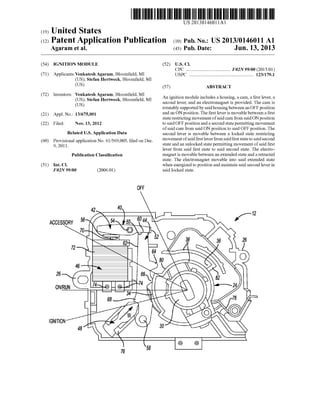
  • 1. (19) US 20130146011A1 (12) Patent Application Publication (10) Pub. No.: US 2013/0146011 A1 United States Agaram et al. (43) Pub. Date: Jun. 13, 2013 (54) (71) (72) (21) (22) (60) (51) IGNITION MODULE ApplicantszVenkatesh Agaram, Bloom?eld, MI (US); Stefan HertWeck, Bloom?eld, MI (US) Inventors: Venkatesh Agaram, Bloom?eld, MI (US); Stefan HertWeck, Bloom?eld, MI (US) Appl. No.: 13/675,001 Filed: Nov. 13, 2012 Related US. Application Data Provisional application No. 61/569,003, ?led on Dec. 9, 201 1 . Publication Classi?cation Int. Cl. F02N 99/00 (2006.01) OFF 42 ACCESSORY 56 26 ON/RUN IGNITION 76 (52) US. Cl. CPC .................................... .. F02N 99/00 (2013.01) USPC ..................................................... .. 123/1791 (57) ABSTRACT An ignition module includes a housing, a cam, a ?rst lever, a second lever, and an electromagnet is provided. The cam is rotatably supported by saidhousing betWeen an OFF position and an ON position. The ?rst lever is movable betWeen a ?rst state restricting movement ofsaid cam from said ON position to said OFF position and a second state permitting movement of said cam from said ON position to said OFF position. The second lever is movable betWeen a locked state restricting movement ofsaid ?rst lever from said ?rst state to said second state and an unlocked state permitting movement of said ?rst lever from said ?rst state to said second state. The electro magnet is movable betWeen an extended state and a retracted state. The electromagnet movable into said extended state When energized to position and maintain said second lever in said locked state. f12
  • 2. Patent Application Publication Jun. 13, 2013 Sheet 1 0f 5 US 2013/0146011 A1 ACCESSORY ON/RUN
  • 3. Patent Application Publication Jun. 13, 2013 Sheet 2 0f 5 US 2013/0146011 A1 [Fig-4
  • 4. Patent Application Publication Jun. 13, 2013 Sheet 3 0f 5 US 2013/0146011 A1
  • 5. Patent Application Publication Jun. 13, 2013 Sheet 4 0f 5 US 2013/0146011 A1 84 Engine Stopped f Passive Electromagnet fsa 96_—P'E|t t I A'Elt tasslve ecromagne ctlve ecromagne 94 Ignition "OFF“ Position fgo [Fig-7 42a 40a 54 60a 52a 76 58 Fig -8
  • 6. Patent Application Publication Jun. 13, 2013 Sheet 5 0f 5 US 2013/0146011 A1
  • 7. US 2013/0146011A1 IGNITION MODULE CROSS-REFERENCE TO RELATED APPLICATION [0001] This application claims the bene?t of US. Provi sional Ser. No. 61/569,003, ?led Dec. 9, 2011. FIELD [0002] The present disclosure relates to ignition modules and more particularly to an ignition module having a release feature permitting removal of a key fob from the ignition module under insu?icient poWer conditions. BACKGROUND [0003] Ignition modules are typically incorporated into a vehicle to permit a driver to selectively control the vehicle from an OFF state to an ON state. Such ignition modules typically include a receptacle that receives a key and/or key fob that, When rotated or depressed, moves the vehicle from the OFF state to the ON state. The key and/or key fob is typically retained Within the ignition When the vehicle is in the ON state to prevent removal ofthe key and/orkey fob from the ignition during use. Once the vehicle is returned to a parked state and the key and/or key fob is returned to an OFF position, the key and/or key fob may be removed from the ignition module. [0004] Vehicle manufacturers have recently incorporated the function ofa conventional key and a conventional key fob into a single unit in a continuing effort to simplify operation and use ofvehicles. Speci?cally, a vehicle may incorporate a Wireless ignition module that interfaces With a key fob With out the need for a conventional key. The key fob functions in a conventional manner in that a user may unlock and lock vehicle doors and may open other access compartments ofthe vehicle (i.e., a trunkor sliding door) but, also, incorporates the functionality ofa conventional key. Namely, the key fob may be inserted into the Wireless ignition module and may com municate With the Wireless ignition module When depressed orrotatedto control the vehicle betWeen the OFF state and the ON state. [0005] A key fob used in conjunction With a Wireless igni tion module is prevented from being removed from the igni tion While the vehicle is in the ON state and the vehicle is not in the parked state. The fob is only permitted to be removed from the ignition module once the vehicle is returned to the parked state and the fob is returned to the OFF position. [0006] Conventional Wireless ignition modules typically incorporate a solenoid that Works in conjunction With a series of linkages to prevent removal of the fob from the ignition module until the vehicle is returned to the OFF state and the fob is returned to the OFF position. At this point, the solenoid may be energiZed to actuate the series of linkages and permit removal of the fob from the ignition module. [0007] While conventional ignition modules adequately maintain engagement of the fob and the ignition module When the vehicle is in the ON state and adequately permit removal ofthe fob from the ignition module When the vehicle is returned to the OFF state, such ignition modules do not permit removal ofthe fob from the ignition module When the vehicle is incapable of providing su?icient poWer to actuate the solenoid. For example, When a battery of the vehicle is dead, poWer cannot be supplied to the solenoid to actuate the linkages and permit removal of the fob from the module. Jun. 13,2013 Under such circumstances, the fob remains locked in the ignition module and cannot be removed until poWer is restored to the vehicle. SUMMARY [0008] An ignition module is provided and may include a housing and a cam rotatably supported by the housing betWeen an OFF position and an ON position. A ?rst lever may be movable betWeen a ?rst state restricting movement of the cam from the ON position to the OFF position and a second state permitting movement of the cam from the ON position to the OFF position. A second lever may be movable betWeen a locked state restricting movement ofthe ?rst lever from the ?rst state to the second state and an unlocked state permitting movement of the ?rst lever from the ?rst state to the second state. An electromagnet may be movable betWeen an extended state and a retracted state and may be movable into the extended state When energiZed to position and main tain the second lever in the locked state. [0009] In another con?guration, an ignition module for a vehicle having an energy source is provided and may include a housing and a cam rotatably supported by the housing betWeen an OFF position and an ON position. A ?rst lever may be movable betWeen a ?rst state restricting movement of the cam from the ON position to the OFF position and a second state permitting movement of the cam from the ON position to the OFF position. A second lever may be movable betWeen a locked state restricting movement ofthe ?rst lever from the ?rst state to the second state and an unlocked state permitting movement of the ?rst lever from the ?rst state to the second state. An electromagnet movable betWeen an extended state and a retracted state may be movable into the extended state to position and maintain the second lever in the locked state. A release mechanism may permit movement of the cam from the ON position to the OFF position When poWer from the energy source is insuf?cient to move the electromagnet betWeen the extended state and the retracted state. [0010] Further areas of applicability of the present inven tion Will become apparent from the detailed description pro vided hereinafter. It should be understood that the detailed description and speci?c examples, While indicating the pre ferred embodiment ofthe invention, are intended forpurposes of illustration only and are not intended to limit the scope of the invention. BRIEF DESCRIPTION OF THE DRAWINGS [0011] The present invention Will become more fully understood from the detailed description and the accompa nying draWings, Wherein: [0012] FIG. 1 is a partial perspective vieW of a passenger compartment ofa vehicle incorporating an ignition module in accordance With the principles ofthe present disclosure; [0013] FIG. 2 is a partial front vieW ofan ignition module in accordance With the principles ofthe present disclosure; [0014] FIG. 3 is a partial rearvieW ofthe ignition module of FIG. 2 shoWn in an OFF state; [0015] FIG. 4 is a partial rearvieW ofthe ignition module of FIG. 2 shoWn in an accessory position betWeen an OFF posi tion and an ON position; [0016] FIG. 5 is a partial rearvieW ofthe ignition module of FIG. 2 shoWn in an ON position;
  • 8. US 2013/0146011Al [0017] FIG. 6 is a partial rearvieW ofthe ignition module of FIG. 2 shown in an OFF position; [0018] FIG. 7 is a ?owchart detailing operation ofthe igni tion module of FIG. 2; [0019] FIG. 8 is a partial rear vieW ofan ignition module in accordance With the principles ofthe present disclosure; [0020] FIG. 9 is a partial rear vieW ofan ignition module in accordance With the principles ofthe present disclosure; and [0021] FIG. 10 is a partial rear vieW of an ignition module in accordance With the principles of the present disclosure. DETAILED DESCRIPTION [0022] The folloWing description ofthe preferred embodi ments is merely exemplary innature and is inno Way intended to limit the invention, its application, or uses. [0023] With reference to the ?gures, a vehicle 10 is pro vided and may include an ignition module 12. The ignition module 12 may be associated With a steering column 14 and steering Wheel 16 of the vehicle 10 such that the ignition module 12 is a subassembly ofthe steering column 14 and is positioned in close proximity to the steering Wheel 16. While the ignition module 12 is described and shoWn as being asso ciatedWith a steering column 14 ofthe vehicle 10, the ignition module 10 could be located anyWhere Within a passenger compartment 18 of the vehicle 10. For example, the ignition module 12 could be located in an instrument panel 20 of the vehicle 10. [0024] The ignition module 12 may be a Wireless ignition module that selectively receives a key fob (not shoWn) for use in controlling the vehicle 10 betWeen an ON state and an OFF state and for supplying poWer to various subsystems of the vehicle 10. For example, the key fob may be used to position the ignition module 12 and, thus, the vehicle 10, in an ACCESSORY state (FIG. 4), that supplies poWer to vehicle accessories such as, for example, a radio 15 or other vehicle instruments 17 but does not change an operating state of the vehicle 10 from the OFF state to the ON state. [0025] The key fob may be an integratedkey fob that alloWs for operation of various subsystems of the vehicle 10 While concurrently alloWing an operator to control the vehicle 10 betWeen the OFF state, the ON state, and the ACCESSORY state. For example, the key fob may permit an operatorto lock and unlock vehicle doors 19, open and close rear or side closure panels depending on the particular vehicle, and/or initiate an alarm function ofthe vehicle 10. The key fob may additionally include an integrated key such that When the key fob is received by the ignition module 12, the key fob alloWs the user to manipulate the ignition module 12 and, thus, the vehicle 10, betWeen the OFF state, the ON state, and the ACCESSORY state. [0026] The ignition module 12 is described as being a Wire less ignition module, as the ignition module Wirelessly com municates With the key fob to properly identify the key fob Whenreceivedby the ignitionmodule 12. Further, the ignition module 12 may control operation of the vehicle 10 amongst the ON state, the OFF state, and the ACCESSORY state by Wirelessly communicatingWith abody controller (not shoWn) ofthe vehicle 10, for example, Whenthekey fob is receivedby the ignition module 12. The ignition module 12 may include a processor and memory (neither shoWn) for accomplishing Wireless communication betWeen the ignition module 12 and the key fob and for accomplishing Wireless communication betWeen the ignition module and the body controller. Jun. 13,2013 [0027] During operation, the ignition module 12 may receive the key fob and may ?rst identify the key fob. If the correct key fob is received by the ignition module 12, the ignition module 12 may alloW an operator to utiliZe the key fob and control the vehicle 10. If, hoWever, an incorrect key fob is received by the ignition module 12, the ignitionmodule 12 may identify the incorrect key fob and Will not permit an operator to control the vehicle 10. [0028] Once the ignition module 12 receives and identi?es the correct key fob, a force may be applied to the key fob to control operation ofthe vehicle 10. For example, the key fob may be rotated into various positions to control an operating state of the vehicle 10. Namely, the key fob may be ?rst rotated from an OFF position to an ACCESSORY position that alloWs an operator to control various subassemblies or accessories ofthe vehicle 10. The key fob may additionally be rotated from theACCESSORY position past the ON position to an IGNITE position in an effort to start an engine (not shoWn) ofthe vehicle 10. Once the engine is started, the key fob may be automatically rotated from the IGNITE position to the ON position When the vehicle 10 is running. Again, because the ignition module 12 may be a Wireless ignition module, When a force is appliedto the key fob to rotate the key fob from the OFF position to the ACCESSORY position, IGNITE position, or ON position, the control module 12 may sense a rotational position of the key fob and may relay the rotational position of the key fob to the body controller to alloW the body controller to properly control the vehicle 10 based on the detected position of the key fob. For example, When the key fob is initially rotated from the OFF position to the IGNITE position, the ignition module 12 identi?es the change in the rotational position from the OFF position to the IGNITE position ofthe key fob and relays the information to the body controller. The body controller may rely on such information in controlling the engine of the vehicle 10 and may cause the engine to start. [0029] During the foregoing operation, removal ofthe key fob from the ignition module 12 is typically restricted until the vehicle 10 is in a parked state and the key fob is returned to the OFF position. As Will be described in greater detail beloW, the ignition module 12 restricts removal ofthe key fob until the vehicle 10 is moved into a parked state and the key fob is rotated into the OFF position. The ignition module 12 additionally permits removal ofthe key fob under conditions When insuf?cient poWer is supplied from the vehicle 10 to the ignition module 12. [0030] With particular reference to FIGS. 2-6, the ignition module 12 is shoWn to include a housing 22 and a cylinder 24 rotatably supported by the housing 22. The housing 22 may include a series ofattachment features 26 that may be used to assemble the ignition module 12 to the steering column 14 or instrument panel 20. The attachment features 26 may position the ignition module 12 relative to and Within the steering column 14 or instrument panel 20 to alloW a portion of the cylinder 24 to be exposed (FIG. 1). [0031] The cylinder 24 is rotatably supported by the hous ing 22 suchthat a ?rst end 28 (FIG. 2) extends from a ?rst side ofthe housing 22 (FIG. 2) and a second end 30 ofthe cylinder 24 extends from an opposite side of the housing 22 (FIGS. 3-6). The ?rst end 28 may include a receptacle 32 that selec tively receives the key fob. When the key fob is received Within the receptacle 32, a force may be applied to the key fob to rotate the key fob and the cylinder 24 relative to the housing 22. As described above, the key fob may be in Wireless com
  • 9. US 2013/0146011Al munication With the ignition module 12 and, as a result, a rotational position of the cylinder 24 and, thus, the key fob relative to the housing 22, may be detected by the ignition module 12 and reported to the vehicle controller. [0032] The second end 30 of the cylinder 24 extends from an opposite side of the housing 22 than the ?rst end 28. The second end 30 may include a cam surface 34 as Well as a guide 36 de?ned by Walls 38 extending from the cylinder 24. [0033] With continued reference to FIGS. 2 and 3, the cyl inder 24 is shoWn as being rotatable betWeen an OFF position, an ACCESSORY position, an ON/RUN position, and an IGNITE position relative to the housing 22. The various posi tions of the cylinder 24 relative to the housing 22 may be accomplished When a key fob is inserted into the receptacle 32 ofthe cylinder 24 and the key fob is rotated relative to the housing 22. [0034] When the key fob is received in the receptacle 32 of the cylinder 24, the ignition module 12 ?rst identi?es the key fob. Ifthe correct key fob is inserted in the receptacle 32, the ignition module 12ivia the body controlleripermits a user to control the vehicle 10 and vehicle subsystems by simply applying a rotational force to the cylinder 24 via the key fob to rotate the cylinder 24 betWeen the various positions shoWn in FIGS. 2 and 3. If, on the other hand, an incorrect key fob is inserted into the receptacle 32 ofthe cylinder 24, the ignition module 24 may identify the key fob as being an incorrect key fob. Upon identifying an incorrect key fob, the ignition mod ule 12 may Wirelessly communicate a signal to the body controller, for example, instructing the body controller to prevent operation ofthe vehicle 10 and any accessories ofthe vehicle 10. Speci?cally, While the key fob and cylinder 24 may be permitted to rotate relative to the housing 22, the ignition module 22 may prevent operation of the vehicle 10 and any vehicle accessories by communicating to the body controller that an incorrect key fob is received in the ignition module 12. [0035] With particular reference to FIGS. 2 and 6, the igni tionmodule 12 is shoWn as including a locking mechanism 40 that selectively prevents rotation ofthe cylinder 24 relative to the housing 22 to prevent inadvertent removal ofthe key fob from the receptacle 32 When the vehicle 10 is in the RUN state, the ACCESSORY state, or the IGNITE state. The lock ing mechanism 40 may include a locking member 42, a lever 44, an electromagnet 46, and a biasing member 48. The lock ing member 42 may include a ?rst engagement surface 50 and a second engagement surface 52 in selective engagement With the lever 44. The locking member 42 may be rotatably sup ported by the housing 22 by a pivot 54 and may be biased in the counterclockWise direction relative to the vieW shoWn in FIG. 3 by a biasing member 56. [0036] The lever 44 may be pivotably supported by the housing 22 by a pivot 58 to permit the lever 44 to move relative to the housing 22 When the cylinder 24 is moved betWeen the OFF state, theACCESSORY state, the ON/RUN state, and the IGNITE state (FIGS. 2 and 3). The lever 44 may include a ?rst engagement surface 60, a second engagement surface 62, an extension 64, a cam folloWer 66, and a shoulder 68. The ?rst engagement surface 60 may be in selective con tact With the ?rst engagement surface 50 ofthe locking mem ber 42 While the second engagement surface 62 may be in selective contact With the second engagement surface 52 of the locking member 42. The extension 64 may be slidably received Within the guide 36 of the cylinder 24 When the cylinder 24 is rotated relative to the housing 22. The cam Jun. 13,2013 folloWer 66 may be disposed proximate to the extension 64 and may contact the cylinder 24 When the cylinder 24 is rotated from the OFF position to any of the ACCESSORY position, the ON/RUN position, or the IGNITE position. The shoulder 68 may extend generally from the lever 44 and may be in contact With the biasing member 48 to alloW the biasing member 48 to apply a force to the lever 44. [0037] Electromagnet 46 may be supported by the housing 22 and may include an output shaft 70 and a Wound core 72. The output shaft 70 may be moved betWeen an extended state (FIGS. 3-5) and a retracted state (FIG. 6) by selectively sup plying current to the Wound core 72 ofthe electromagnet 46. The current may be supplied to the Wound core 72 at one or more terminals 74 that are in electrical communication With the Wound core 72. [0038] The biasing member 48 may be received Within a seat 76 of the housing 22 to alloW attachment of the biasing member 48 to the housing 22. The biasing member 48 may include a spring or other biasing element (not shoWn) that exerts a force on the shoulder 68 ofthe lever 44 in a direction W. The force exerted on the lever 44 at the shoulder 68 causes the lever 44 to be biased in the clockWise direction relative to the vieWs shoWn in FIGS. 3-5. [0039] With particular reference to FIGS. 2-6, operation of the ignition module 12 Will be described in detail. When the vehicle 10 is initially at rest, the ignition module 12 is in the OFF position (FIGS. 2 and 3). The ignitionmodule 12 may be biased into the OFF position by a biasing element 78 that applies a force to the cylinder 24, thereby causingthe cylinder 24 to be biased in the clockWise direction relative to the vieWs shoWn in FIGS. 3-5. [0040] A key fob may be inserted into the receptacle 32 to alloW an operator to rotate the cylinder 24 relative to the housing 22. When the key fob is initially received in the receptacle 32, the ignition module 12 may ?rst identify the key fob via Wireless communication. If the key fob is not identi?ed or is identi?ed as being an incorrect key fob, the ignition module 12 may permit rotation of the key fob and cylinder 24 relative to the housing 22 but Will send a signal to the body controller ofthe vehicle 10, for example, to prevent use of the vehicle 10 and any vehicle accessories. If, on the otherhand, the ignition module 12 recogniZes the key fob, the ignition module 12 Will permit the user to not only rotate the key fob and cylinder 24 relative to the housing 22 but, also, Will permit use ofthe vehicle 10 and any vehicle accessories by sending a signal to the body controller that the correct key is disposed Within the receptacle 32. [0041] A force may be applied to the cylinder 24 to rotate the cylinder 24 relative to the housing 22 by applying a rotational force to the key fob. When the cylinder 24 is ini tially rotated relative to the housing 22, the cylinder 24 is rotated from the OFF position to the ACCESSORY position. At this point, the electromagnet 46 is energiZed, thereby causing the output shaft 70 ofthe electromagnet 46 to extend from the Wound core 72 and apply a force on the locking member 42. The force applied to the locking member 42 causes the locking member 42 to rotate in the clockWise direction relative to the vieWs shoWn in FIGS. 3-5 about the pivot 54. [0042] When the cylinder 24 is suf?ciently rotated in the counterclockWise direction relative to the vieWs shoWn in FIGS. 3-5 from the OFF position to the ACCESSORY posi tion, the cam folloWer 66 ofthe lever 44 disengages the cam surface 34 of the cylinder 24 and, as a result, permits the
  • 10. US 2013/0146011A1 biasing member 48 to rotate the lever 44 in the clockwise direction relative to the views shown in FIGS. 3-5 about the pivot 58. [0043] Whenthe lever 44 is suf?ciently rotated inthe clock wise direction relative to the views shown in FIGS. 3-5, the ?rst engagement surface 50 ofthe locking member 42 disen gages the ?rst engagement surface 60 ofthe lever 44, thereby allowing the output shaft 70 ofthe electromagnet 46 to rotate the locking member 42 about the pivot 54 clockwise such that the second engagement surface 52 ofthe locking member 42 contacts the second engagement surface 62 of the lever 44 (FIG. 4). At this point, the cylinder 24 is in the accessory position and the extension 64 and cam follower 66 ofthe lever 44 are in contact with the wall 38 ofthe cylinder 24, with the extension 64 being at least partially received within the guide 36. When the ignition module 12 is in the ACCESSORY position, the ignition module 12 may send a signal to the body controller, instructing the body controllerto provide powerto the accessories of the vehicle 10 to allow the operator to use the various accessories of the vehicle 10. [0044] When the cylinder 24 is in the ACCESSORY posi tion, such that the locking member 42 is permitted to rotate in the clockwise direction relative to the views shown in FIGS. 3-5, the second engagement surface 52 ofthe locking member 42 may contact the second engagement surface 62 ofthe lever 44 to prevent rotation ofthe lever 44 about the pivot 58 in the counterclockwise direction relative to the views shown in FIGS. 3-5. Preventing rotation of the lever 44 relative to the housing 22 in the counterclockwise direction relative to the views shown in FIGS. 3-5 prevents the cylinder 24 from returning to the OFF position and, thus, prevents removal of the key fob from the receptacle 32. Speci?cally, the key fob may only be removed from the receptacle 32 of the cylinder 24 when the cylinder 24 is in the OFF position. Therefore, if the cylinder 24 is prevented from returning to the OFF posi tion due to engagement between the locking member 42 and the lever 44, the key fob will remain within the receptacle 32 and is prevented from being removed from the cylinder 24 when the cylinder 24 is in the ACCESSORY position. [0045] If the force applied to the key fob is released when the cylinder 24 is intheACCESSORY position, the engine of the vehicle 10 remains offwhile accessories ofthe vehicle 10 may be used. Again, the ignition module 12 may communi cate with the body controller to instruct the body controller to provide power to the accessories of the vehicle 10 when the cylinder 24 is in the ACCESSORY position. The ignition module 12 may identifytheACCESSORYpositionby detect ing a rotational position of the cylinder 24 relative to the housing 22. The ignition module 12 will remain in the ACCESSORY position until a force is applied to the cylinder 24 via the key fob to either return the cylinder 24 to the OFF position or to advance the cylinder 24 in the opposite rota tional direction into the IGNITE position and, ?nally, into the ON/RUN position. [0046] If a rotational force is applied to the cylinder 24 via the key fob such that the cylinder 24 is returned to the OFF positionfromtheACCESSORYposition, the ignitionmodule 12 identi?es the rotational movement ofthe cylinder 24 rela tive to the housing 22 and instructs the electromagnet 46 to retract the output shaft 70 into the wound core 72 to allow the locking member 42 to rotate in the counterclockwise direc tion relative to the views shown in FIGS. 3-5 such that the second engagement surface 52 of the locking member 42 disengages the second engagement surface 62 ofthe lever 44. Jun. 13,2013 The locking member 42 is rotated in the counterclockwise direction relative to the views shown in FIGS. 3-5 by the biasing member 56 disposed generally between the locking member 42 and the electromagnet 46. Therefore, when cur rent is restricted from ?owing to the electromagnet 46, the output shaft 70 retracts into the wound core 72, thereby allow ing the biasing member 56 to rotate the locking member 42 in the counterclockwise direction relative to the views shown in FIGS. 3-5 and out of engagement with the lever 44. [0047] When the locking member 42 is disengaged from the lever 44, a rotational force applied to the cylinder 24 at the key fob causes the cam surface 34 ofthe cylinder 24 to engage the cam follower 66 ofthe lever 44 to rotate the lever 44 in the counterclockwise direction relative to the views shown in FIGS. 3-5 about the pivot 58 and against the biasing force exerted on the shoulder 68 of the lever 44 by the biasing member 48. In other words, permitting rotation ofthe lever 44 in the counterclockwise direction relative to the views shown in FIGS. 3-5 permits the cylinder 24 to be rotated from the ACCESSORY position to the OFF position. [0048] Ifthe force applied to the cylinder 24 via the key fob rotates the cylinder 24 from the ACCESSORY position to the IGNITE position, the extension 64 and cam follower 66 ofthe lever 44 ride along an outer surface 80 ofthe wall 38 andmove further into the guide 36. The guide 36 may include a stop 82 that restricts rotation of the cylinder 24 in the counterclock wise direction relative to the views shown in FIGS. 3-5 past the IGNITE position. For example, as the cylinder 24 is rotated from the ACCESSORY position to the IGNITE posi tion and the extension 64 of the lever 44 moves within the guide 36 toward the stop 82, the extension 64 will eventually contact the stop 82, thereby preventing further rotation ofthe cylinder 24 in the counterclockwise direction relative to the views shown in FIGS. 3-5. [0049] When the cylinder 24 is rotated from the ACCES SORY position to the IGNITE position, the second engage ment surface 52 ofthe locking member 42 maintains engage ment with the second engagement surface 62 ofthe lever 44 to prevent rotation of the lever 44 about the pivot 58 in the counterclockwise direction relative to the views shown in FIGS. 3-5. As described above, preventing rotation of the lever 44 in the counterclockwise direction relative to the views shown in FIGS. 3-5 prevents removal of the key fob from the receptacle 32 when the cylinder 24 is in any of the ACCESSORY position, the ON/RUN position, or the IGNITE position. Once the cylinder 24 reaches the IGNITE position, the force applied to the key fob may be released. Releasing the force applied to the key fob allows the biasing element 78 to rotate the cylinder 24 in the clockwise direction relative to the views shown in FIGS. 3-5 to move the cylinder 24 from the IGNITE position to the ON/RUN position. [0050] The cylinder 24 is permitted to rotate from the IGNITE position to the ON/RUN position and in the clock wise direction relative to the view shown in FIG. 3, as the cam follower 66 is permitted to move along the surface 80 of the cylinder 24 between the ACCESSORY position, the ON/RUN position, and the IGNITE position without apply ing a force on the lever 44. Speci?cally, the surface 80 is substantially constant and, as a result, does not apply a force on the lever 44 at the cam follower 66 when the cylinder 24 is rotated relative to the lever 44 between the ACCESSORY position, the ON/RUN position, and the IGNITE position, as the cam follower 66 simply traverses the constant surface 80 when the cylinder 24 is rotated relative to the housing 22
  • 11. US 2013/0146011A1 between the various positions. Further rotation ofthe cylinder 24 into the OFF position is prevented, as the cam follower 66 would necessarily disengage surface 80 and engage cam sur face 34, thereby causing a force to be applied to the lever 44. The applied force urges the lever 44 to rotate about pivot 58 in the counterclockwise direction relative to the view shown in FIG. 3. However, the lever 44 is prevented from rotating in the counterclockwise direction relative to the view shown in FIG. 3 until the electromagnet 46 is de-energiZed and the locking member 42 is disengaged from the lever 44. [0051] At this point, the ignition module 12 detects the rotational position ofthe cylinder 24 relative to the housing 22 and identi?es the position to the body controller, for example. The body controller, upon receiving the position of the cyl inder 24, causes the engine to start when the cylinder 24 is in the IGNITE position and continues operation ofthe engine of the vehicle 10 when the cylinder 24 is in the ON/RUN posi tion. [0052] The engine of the vehicle 10 will continue to run, provided the cylinder 24 is maintained in the ON/RUN posi tion. However, when a force is applied to the cylinder 24 to rotate the cylinder 24 in the clockwise direction relative to the views shown in FIGS. 3-5, the cylinder 24 is rotated from the ON/RUN position toward the ACCESSORY position and OFF position. When the cylinder 24 reaches the OFF posi tion, the ignition module 12 identi?es the position of the cylinder 24 relative to the housing 22 and stops the supply of current provided to the electromagnet 46. Restricting current to the electromagnet 46 causes the output shaft 70 to retract into the wound core 72. Retraction of the output shaft 70 allows the biasing member 56 to exert a force on the locking member 42 and rotate the locking member 42 about the pivot 54 in the counterclockwise direction relative to the views shown in FIGS. 3-5. [0053] Upon suf?cientrotation ofthe lockingmember42 in the counterclockwise direction relative to the views shown in FIGS. 3-5, the second engagement surface 52 of the locking member 42 disengages the second engagement surface 62 of the lever 44, thereby allowing the lever 44 to be rotated in the counterclockwise direction relative to the views shown in FIGS. 3-5. The lever 44 is caused to rotate in the counter clockwise direction relative to the views shown in FIGS. 3-5 due to engagement between the extension 64 and cam fol lower 66 with the cam surface 34 of the cylinder 24. The extension 64 and cam follower 66 engage the cam surface 34 when the cylinder 24 is suf?ciently rotated in the clockwise direction relative to the views shown in FIGS. 3-5. Rotation of the lever 44 in the counterclockwise direction relative to the views shown in FIGS. 3-5 about the pivot 58 causes the lever 44 to move against the force exerted on the shoulder 68 ofthe lever 44 by the biasing member 48. [0054] When the cylinder 24 is returned to the OFF posi tion, the ?rst engagement surface 50 of the locking member 42 may be in contact with the ?rst engagement surface 60 of the lever 44. The lever 44 may be maintained in the position shown in FIG. 6 due to engagement between the cam follower 66 of the lever 44 and the cam surface 34 of the cylinder 24. At this point, a force may be exerted on the key fob to remove the key fob from the receptacle 32 as the cylinder 24 is returned to the OFF position. [0055] As described above, when current is supplied to the electromagnet 46, the output shaft 70 extends from the wound core 72 and prevents the biasing member 56 from rotating the locking member 42 in the counterclockwise direction relative Jun. 13,2013 to the views shown in FIGS. 3-5.As such, the locking member 42 is positioned to engage the lever 44 when the cylinder 24 is rotated in the counterclockwise direction relative to the views shown in FIGS. 3-5 to prevent the lever 44 from rotat ing in the counterclockwise direction relative to the views shown in FIGS. 3-5 in an effort to prevent removal ofthe key fob from the receptacle 32 ofthe cylinder 24 when the cylin der 24 is in any of the ACCESSORY position, the ON/RUN position, or the IGNITE position. In short, when the cylinder 24 is moved into any of the ACCESSORY position, the ON/RUN position, or the IGNITE position, current is con tinually supplied to the electromagnet 46 to ensure that the output shaft 70 extends from the wound core 72 and prevents rotation of the locking member 42 in the counterclockwise direction relative to the views shown in FIGS. 3-5. [0056] Should the vehicle 10 experience a power failure such as, for example, a dead battery during use, the current supplied to the electromagnet 46 will cease. Therefore, the output shaft 70 will automatically move into the wound core 72 and the biasing member 56 will be permitted to apply a force on the locking member 42 to rotate the locking member 42 in the counterclockwise direction relative to the views shown in FIGS. 3-5. As described above, permitting rotation of the locking member 42 in the counterclockwise direction relative to the views shown in FIGS. 3-5 permits the lever 44 to likewise be rotated in the counterclockwise direction rela tive to the views shown in FIGS. 3-5 when the cylinder 24 is rotated in the clockwise direction relative to the views shown in FIGS. 3-5. Suf?cient rotation of the cylinder 24 in the clockwise direction relative to the views shown in FIGS. 3-5 allows the cylinder 24 to be moved into the OFF position, which allows an operator to apply a force on the key fob to remove the key fob from the receptacle 32. Therefore, even when the vehicle 10 experiences a power outage, an operator is permitted to remove the key fob from the ignition module 12. [0057] With particular reference to FIG. 7, a ?owchart is providedthat summarizes the foregoing operation ofthe igni tion module 12. Namely, the ignition module 12 will detect that the engine is stopped at 84. The ignition module 12 will then determine whether the vehicle 10 is in the parked posi tion at 86. If the vehicle 10 is in the parked position at 86, current will not be supplied to the electromagnet 46, thereby resulting in the electromagnet 46 being a so-called “passive” electromagnet 46 at 88. When the electromagnet 46 is not supplied with current, the cylinder 24 may be moved into the OFF position at 90 and the key fob may be removed from the ignition module 12, as previously described. [0058] Ifthe vehicle 10 is not in the parked position at 86, the ignitionmodule 12 will then determine whether the power source of the vehicle 10 is alive at 92. Ifthe power source of the vehicle 10 is determined to be alive at 92, the ignition module 12 will supply the electromagnet 46 with current at 94 to prevent the biasing member 56 from rotating the locking member 42 in the counterclockwise direction relative to the views shown in FIGS. 3-5. As described above, preventing the locking member 42 from rotating in the counterclockwise direction relative to the views shown in FIGS. 3-5 after the cylinder 24 is moved into any ofthe ACCESSORY position, the ON/RUN position, or the IGNITE position prevents the cylinder 24 from rotating in the clockwise direction relative to the views shown in FIGS. 3-5 and, thus, prevents removal of the key fob from the ignition module 12. The cylinder 24 may be moved into the OFF position at 90 only when the current
  • 12. US 2013/0146011Al supplied to the electromagnet 46 is stopped. Restricting cur rent to the electromagnet 46 permits the biasing member 56 to rotate the locking member 42 out of engagement With the lever 44, Which permits the cylinder 24 to rotate in the clock Wise direction relative to the vieWs shoWn in FIGS. 3-5 and into the OFF position. Once in the OFF position, the key fob may be removed from the ignition module 12. [0059] Ifthe ignition module 12 determines that the poWer source ofthe vehicle 10 is not alive at 92, current cannot and is not supplied to the electromagnet 46, Which results in the electromagnet 46 being passive at 96. When the electromag net 46 is not supplied or cannot be supplied With current, the output shaft 70 is retracted into the Wound core 72, thereby alloWing the biasing member 56 to once again rotate the locking member 42 out of engagement With the lever 44, Which alloWs the cylinder 24 to be rotated in the clockWise direction relative to the vieWs shoWn in FIGS. 3-5 and into the OFF position at 90. Once the cylinder 24 is returned to the OFF position, a force may be applied to the key fob to remove the key fob from the ignition module 12. [0060] With particular reference to FIG. 8, an ignitionmod ule 12a for use With the vehicle 10 is provided. In vieW ofthe substantial similarity in structure and function ofthe compo nents associated With the ignition module 12 With respect to the ignition module 12a, like reference numerals are used hereinafter and in the draWings to identify like components While like reference numerals containing letter extensions are used to identify those components that have been modi?ed. [0061] The ignition module 1211 is substantially similar to the ignition module 12 With the exception that the ignition module 1211 includes a locking mechanism 40a in place ofthe locking mechanism 40. The locking mechanism 40a may include a locking member 42a pivotably supported by a pivot 54 and a lever 44a pivotably supported by a pivot 58. The locking member 42 may include a ?rst engagement surface 50a and a second engagement surface 52a. LikeWise, the lever 44 may include a ?rst engagement surface 60a and a second engagement surface 6211. Other than the ?rst and second engagement surfaces 50a, 52a ofthe locking member 42a and the ?rst and second engagement surfaces 60a, 62a of the lever 4411, the locking member 4211 and lever 4411 are identical to the locking member 42 and lever 44 ofthe ignition module 12. As such, a detailed description of the remaining features ofthe locking member 42a and lever 44a is foregone. [0062] With continued reference to FIG. 8, operation ofthe ignition module 1211 Will be described in detail. When the key fob is inserted into the receptacle 32 of the cylinder 24, the cylinder 24 may be rotated from the OFF position to any ofthe ACCESSORY position, the ON/RUN position, or the IGNITE position. Once the cylinder 24 is moved into one of the ACCESSORY position, the ON/RUN position, or the IGNITE position, the biasing member 56 is permitted to rotate the locking member 42a in the clockWise direction relative to the vieW shoWn in FIG. 8. Speci?cally, current is initially restricted from the electromagnet 46, thereby caus ing the electromagnet 46 to become passive. When the elec tromagnet 46 is passive, the biasing member 56 is permitted to extend the output shaft 70 and rotate the locking member 42a in the clockWise direction relative to the vieW shoWn in FIG. 8. [0063] For example, shouldthe cylinder 24 be rotated from the OFF position to the ON/RUN position, current Will be restricted from reaching the electromagnet 46, Which alloWs the biasing member 56 to rotate the locking member 4211 in Jun. 13,2013 the clockWise direction relative to the vieW shoWn in FIG. 8. Rotation of the locking member 42a in the clockWise direc tion relative to the vieW shoWn in FIG. 8 causes the second engagement surface 52a ofthe locking member 4211 to engage the second engagement surface 62a ofthe lever 44a to prevent rotation of the lever 44a in the counterclockWise direction relative to the vieW shoWn in FIG. 8. Preventing rotation ofthe lever 44a in the counterclockWise direction relative to the vieW shoWn in FIG. 8 likeWise prevents rotation ofthe cylin der 24 in the clockWise direction relative to the vieW shoWn in FIG. 8 and into the OFF position due to engagement betWeen the cam folloWer 66 and the outer surface 80 of the cylinder 24, as described above With respect to the ignition module 12. Preventing rotation ofthe cylinder 24 in the clockWise direc tion relative to the vieW shoWn in FIG. 8 prevents rotation of the cylinder 24 from the ON/RUN position to the OFF posi tion and, therefore, prevents removal ofthe key fob from the receptacle 32. [0064] The cylinder 24 may be returned to the OFF position by supplying current to the electromagnet 46. Speci?cally, supplying current to the electromagnet 46 causes the output shaft 70 to retract into the Wound core 72 and, thus, causes rotation of the locking member 42a in the counterclockWise direction relative to the vieW shoWn in FIG. 8 against the biasing member 56. Speci?cally, the locking member 4211 is ?xed to the output shaft 70. Therefore, When the output shaft 70 is retracted into the Wound core 72, the locking member 4211 is rotated in the counterclockWise direction relative to the vieW shoWn in FIG. 8. The key fob may be removed from the receptacle 32 once the cylinder 24 is returned to the OFF position. [0065] Should the poWer source ofthe vehicle 10 be insuf ?cient to provide current to the electromagnet 46 such as, for example, When a battery ofthe vehicle 10 is dead, a force may be applied to the cylinder 24 via the key fob to override the locking member 4211. Namely, because the second engage ment surface 52a of the locking member 4211 is formed at substantially the same angle as is the second engagement surface 62a ofthe lever 44a such that the second engagement surface 52a ofthe locking member 42a mates With the second engagement surface 62a of the lever 4411, When a force is applied to the cylinder 24 inthe clockWise direction relative to the vieW shoWn in FIG. 8, the second engagement surface 62a ofthe lever 44a is permitted to slide along the second engage ment surface 52a of the locking member 42a. [0066] AlloWing the second engagement surface 62a ofthe lever 44a to slide along the second engagement surface 52a of the locking member 42a applies a force on the locking mem ber 42a and causes the biasing member 56 to compress. Such movement ofthe lever 44a in the counterclockWise direction is caused by rotation of the cylinder 24 in the clockWise direction relative to the vieW shoWn in FIG. 8 once the cam surface 34 ofthe cylinder 24 contacts the cam folloWer 66 of the lever 44a. [0067] While the force applied to the cylinder 2411 must be suf?cient to overcome the force applied to the locking mem ber 4211 by the biasing member 56, the required force is mitigated due to the substantially sloped surfaces ofthe sec ond engagement surfaces 52a, 62a of the locking member 4211 and lever 44a, respectively. Therefore, When the poWer source of the vehicle 10 is insuf?cient or otherWise unavail able and the electromagnet 46 cannot be actuated to rotate the locking member 42 in the counterclockWise direction relative to the vieW shoWn in FIG. 8, a force may be applied to the
  • 13. US 2013/0146011A1 cylinder 24 to rotate the cylinder from any of the IGNITE position, ON/RUN position, or ACCESSORY position back to the OFF position to alloW removal ofthe key fob from the receptacle 32. [0068] With particular reference to FIG. 9, an ignitionmod ule 12b for use With the vehicle 10 is provided. In vieW ofthe substantial similarity in structure and function ofthe compo nents associated With the ignition module 12 With respect to the ignition module 12b, like reference numerals are used hereinafter in the draWings to identify like components While like reference numerals containing letter extensions are used to identify those components that have been modi?ed. [0069] The ignitionmodule 12b is substantially identical to the ignition module 12 With the exception that the ignition module 12b includes a locking mechanism 40b in place ofthe locking mechanism 40. The locking mechanism 40b may include a locking member 42b and a lever 40b. The locking member 42b is similar to the locking member 42 of the ignition module 12; hoWever, the locking member 42b includes an elongated portion 98 and a hook portion 100 extending from the elongated portion 98. The lever 44b is similar to the lever 44 ofthe ignition module 12; hoWever, the cam folloWer 66b ofthe lever 44b may extend from the lever 44b to a lesser extent than the cam folloWer 66 ofthe lever 44. [0070] In operation, a force may be applied to the cylinder 24 to rotate the cylinder 24 from the OFF position to any ofthe ACCESSORY position, the ON/RUN position, or the IGNITE position. Under normal operating conditions, the cylinder 24 may be rotated into the ON/RUN position by rotating the cylinder 24 in the counterclockWise direction relative to the vieW shoWn in FIG. 9, Which causes a force to be applied to the lever 44b due to interaction betWeen the cam folloWer 66b and the cam surface 34 of the cylinder 24. [0071] When the poWer source of the vehicle 10 is su?i cient, poWer may be supplied to the electromagnet 46 to alloW the cylinder 24 to be rotated inthe clockWise direction relative to the vieW shoWn in FIG. 9 to return to the OFF position from any ofthe ACCESSORY position, the ON/RUN position, or IGNITE position. Speci?cally, supplying poWer to the elec tromagnet 46 causes the output shaft 70 to be retracted into the Wound core 72, Which causes the locking member 42b to be rotated in the counterclockWise direction relative to the vieW shoWn in FIG. 9 and out of engagement With the lever 44b. Once the locking member 42b is suf?ciently rotated in the counterclockWise direction, the lever 44b is then permit ted to rotate in the counterclockWise direction relative to the vieW shoWn in FIG. 9 When the cylinder 24 is rotated in the clockWise direction relative to the vieW shoWn in FIG. 9 When the cam folloWer 66b engages the cam surface 34 of the cylinder 24. Once the cylinder 24 is returned to the OFF position, the key fob may be removed from the receptacle 32 of the ignition module 12b. [0072] When the poWer source ofthe vehicle 10 is insu?i cient or otherWise unavailable and, therefore, cannot supply current to the electromagnet 46, the lever 44b is restricted from disengaging the locking member 42b to alloW an opera tor to move the cylinder 24 back to the OFF position and remove the key fob from the receptacle 32 once the cylinder 24 reaches the IGNITE position. Speci?cally, the elongated portion 98 ofthe locking member42 slidablyreceives the ?rst engagement surface 60 of the lever 44b and permits the ?rst engagement surface 60 of the lever 44b to slide generally along the elongated portion 98 until reaching the projection 100. Whether or not the poWer supply of the vehicle 10 is Jun. 13,2013 available, When the cylinder 24 is rotated from the OFF posi tion to any ofthe ACCESSORY position, the ON/RUN posi tion, or the IGNITE position, the ?rst engagement surface 60 ofthe lever 44b is in engagement With the elongated surface 98 of the locking member 42 and does not disengage the locking member 42 until the vehicle 10 is moved into the ON state. [0073] As the cylinder 24 is rotated in a counterclockWise direction relative to the vieW shoWn in FIG. 9 and the cam folloWer 66b disengages the cam surface 34 and moves into the guide 36 of the cylinder 24, the lever 44b rotates in the clockWise direction relative to the vieW shoWn in FIG. 9. HoWever, the ?rst engagement surface 60 of the lever 44b maintains engagement With the elongated portion 98 of the locking member 42 and continues to rotate in the clockWise direction relative to the vieW shoWn in FIG. 9 until the second engagement surface 62 contacts the projection 100. At this point, the lever 44b is prevented from further rotating in the clockWise direction relative to the vieW shoWn in FIG. 9 until the locking member 42b is rotated in the counterclockWise direction relative to the vieW shoWn in FIG. 9 such that the projection 100 disengages the second engagement surface 62 ofthe lever 44b. [0074] Once the projection 100 of the locking member 42 disengages the second engagement surface 62 of the lever 44b, the lever 44b is permitted to continue to rotate in the clockWise direction relative to the vieW shoWn in FIG. 9. The locking member 42b is permitted to rotate in the counter clockwise direction relative to the vieW shoWn in FIG. 9 When current is supplied to the electromagnet 46, thereby causing retraction of the output shaft 70 into the Wound core 72 against the biasing member 56. [0075] If the poWer source of the vehicle 10 is insuf?cient or otherWise unavailable to cause the output shaft 70 to retract into the Wound core 72 and rotate the locking member 42b in the counterclockWise direction relative to the vieW shoWn in FIG. 9, the lever 44b never disengages the projection 100 of the locking member 42b When the cylinder 24 is moved into the ACCESSORY position, the ON/RUN position, or the IGNITE position. Therefore, if a force is applied to the cyl inder 24 to rotate the cylinder 24 from the OFF positionto any of the ACCESSORY position, the ON/RUN position, or the IGNITE position When the poWer source of the vehicle 10 is insuf?cient or otherWise unavailable, the cylinder 24 may be rotated to the OFF position and the key fob may be removed. Speci?cally, When a force is applied to the cylinder 24 to rotate the cylinder 24 in the clockWise direction relative to the vieW shoWn in FIG. 9 from any of the IGNITE position, the ON/RUN position, or the ACCESSORY position back to the OFF position, the cam surface 34 of the cylinder 24 is per mitted to engage the cam folloWer 66 of the lever 44b and is permitted to rotate the lever 44b in the counterclockWise direction relative to the vieW shoWn in FIG. 9. Such rotation ofthe lever 44b in the counterclockWise direction relative to the vieW shoWn in FIG. 9 is permitted because the ?rst engagement surface 60 of the lever 44b is maintained in engagement With the extension 98 ofthe locking member 42 and is maintained generally betWeen the pivot 54 and the projection 100, Which alloWs the lever 44b to essentially freely move betWeen the pivot 54 and the projection 100 along the extension 98. [0076] Rotating the cylinder 24 in the clockWise direction relative to the vieW shoWn in FIG. 9 may be facilitated by providing the lever 44b With a cam folloWer 66b that extends
  • 14. US 2013/0146011A1 from the lever 44b to a lesser extent than the cam follower 66 ofthe ignition module 12, for example. Further, spacing the ?rst engagement surface 60 from the elongated portion 98 of the locking member 42b a smaller distance than a distance the projection 100 extends from the locking member 42 Will likeWise reduce the efforts required to rotate the cylinder 24 from any of the IGNITE position, the ON/RUN position, or the ACCESSORY POSITION back to the OFF position should the vehicle 10 experience a reduced-poWer condition. Once the cylinder 24 is returned to the OFF position, the key fob may be removed from the receptacle 32. [0077] With particular reference to FIG. 10, an ignition module 120 is provided. In vieW of the substantial similarity in structure and function of the components associated With the ignition module 12 With respect to the ignition module 120, like reference numerals are used hereinafter in the draW ings to identify like components While like reference numer als containing letter extensions are used to identify those components that have been modi?ed. [0078] The ignition module 120 is virtually identical to the ignition module 12 With the exception that the ignition mod ule 120 includes a locking mechanism 400 in place of the locking mechanism 40. The locking mechanism 400 is sub stantially identical to the locking mechanism 40 except for locking member 420. Locking member 420 may include a biasing element 102 disposed betWeen a main body 103 and a movable member 104. The biasing element 102 may bias the movable member 104 in a direction substantially aWay from the main body 103 and into engagement With the lever 44. The movable member 104 may include a projection 105 extending generally toWard the lever 44. [0079] In operation, the cylinder 24 may be moved from the OFF position to any of the ACCESSORY position, the ON/RUN position, or the IGNITE position. In so doing, the cylinder 24 may be rotated in the counterclockWise direction relative to the vieW shoWn in FIG. 10, Which likeWise causes rotation ofthe lever 440 in the clockWise direction relative to the vieW shoWn in FIG. 10. If, for example, the cylinder 24 is rotated in the counterclockWise direction relative to the vieW shoWn in FIG. 10 and into the ACCESSORY position, the biasing member 56 Will exert a force on the main body 103, thereby causing the locking member 420 to rotate in the clockWise direction relative to the vieW shoWn in FIG. 10 and engage the second engagement surface 620 of the lever 440. The locking member 420 is permitted to rotate in the clock Wise direction relative to the vieW shoWn in FIG. 10, as the electromagnet 46ito Which the locking member 420 is ?xed for movementiis in a passive state. In other Words, current is not supplied to the electromagnet 46 and therefore, the bias ing member 56 is permitted to rotate the locking member 420 inthe clockWise direction, thereby causing the output shaft 70 to extend from the Wound core 72. [0080] Su?icient rotation ofthe locking member 420 in the clockWise direction relative to the vieW shoWn in FIG. 10 causes the moveable member 104 ofthe locking member 420 to contact the lever 44. Engagement betWeen the movable member 104 of the locking member 420 and the second engagement surface 62 ofthe lever 44 restricts rotation ofthe lever 44 in the counterclockWise direction relative to the vieW shoWn in FIG. 10 and therefore prevents the cylinder 24 from rotating into the OFF state. [0081] As described above, restricting rotation ofthe lever in the counterclockWise direction relative to the vieW shoWn in FIG. 10 restricts rotation ofthe cylinder 24 in the clockWise Jun. 13,2013 direction relative to the vieW shoWn in FIG. 10 and into the OFF position due to engagement betWeen the cam folloWer 66 and the outer surface 80 of the cylinder 24. Should the operator Wishto move the cylinder 24 from theACCESSORY position to the OFF position to alloW removal of the key fob from the receptacle 32, current may be supplied to the elec tromagnet 46 to retract the output shaft 70 into the Wound core 72, thereby causing the locking member 420 to rotate in the counterclockWise direction relative to the vieW shoWn in FIG. 10. Once the locking member 420 is suf?ciently rotated in the counterclockWise direction relative to the vieW shoWn in FIG. 10, the lever 44 may be rotated in the counterclockWise direc tion relative to the vieW shoWn in FIG. 10 due to engagement betWeen the cam folloWer 66 of the lever 44 and the cam surface 34 of the cylinder 24. Once the cylinder 24 is su?i ciently rotated in the clockWise direction relative to the vieW shoWn in FIG. 10 such that the cylinder 24 is returned to the OFF position, the key fob may be removed from the recep tacle 32. [0082] If the poWer source of the vehicle 10 is insuf?cient or otherWise unavailable, current cannot be supplied to the electromagnet 46. Therefore, the output shaft 70 cannot be WithdraWn into the Wound core 72 and the locking member 420 cannot be rotated in the counterclockWise direction rela tive to the vieW shoWn in FIG. 10. As such, the locking member 420 is maintained in engagement With the lever 44 and prevents the lever 44 from rotating in the counterclock Wise direction relative to the vieW shoWn in FIG. 10 and, thus, prevents rotation of the cylinder 24 from any of the IGNITE position, the ON/RUN position, or the ACCESSORY posi tion into the OFF position, ifa su?icient force is applied to the cylinder 24 in an effort to rotate the cylinder 24 in the clock Wise direction and into the OFF position, a force may be exerted on the lever 44 by the cylinder 24, as the cylinder 24 rotates inthe clockWise directionrelative to the vieW shoWn in FIG. 10. The force applied on the lever 44 causes the lever 44 to rotate in the counterclockWise direction relative to the vieW shoWn in FIG. 10 and causes the lever 44 to apply a force on the locking member 420 in a direction substantially along a longitudinal axis ofthe locking member 420. [0083] The force applied along the longitudinal axis ofthe locking member 420 causes the movable member 104 to compress the biasing element 102 disposed betWeen the mov able member 104 and the main body 103. As such, the mov able member 104 moves toWard the main body 103 and reduces the overall effective length of the locking member 420. Once the movable member 104 is suf?ciently moved toWard the main body 103, the effective length ofthe locking member 420 is reduced and the lever 44 is permitted to rotate in the counterclockWise direction relative to the vieW shoWn in FIG. 10. [0084] When the lever 44 is permitted to rotate in the coun terclockWise direction relative to the vieW shoWn in FIG. 10, the cylinder 24 is permitted to rotate in the clockWise direc tion relative to the vieW shoWn in FIG. 10 and is permitted to move from any of the IGNITE position, the ON/RUN posi tion, or the ACCESSORY position into the OFF position. As With the ignition modules 12, 12a, 12b, When the cylinder 24 is returned to the OFF position, a force may be applied to the key fob to remove the key fob from the receptacle 32. [0085] The description of the invention is merely exem plary in nature and, thus, variations that do not depart fromthe gist ofthe invention are intended to be Within the scope ofthe
  • 15. US 2013/0146011Al invention. Such variations are not to be regarded as a depar ture from the spirit and scope of the invention. What is claimed is: 1. An ignition module comprising: a housing; a cam rotatably supported by said housing betWeen an OFF position and an ON position; a ?rst lever movable betWeen a ?rst state restricting move ment of said cam from said ON position to said OFF position and a second state permitting movement ofsaid cam from said ON position to said OFF position; a second lever movable betWeen a locked state restricting movement of said ?rst lever from said ?rst state to said second state and an unlocked state permitting movement ofsaid ?rst lever from said ?rst state to said second state; and an electromagnet movable betWeen an extended state and a retracted state, said electromagnet movable into said extended state When energiZed to position and maintain said second lever in said locked state. 2. The ignitionmodule ofclaim 1, further comprising a ?rst biasing element operable to bias said second lever into said unlocked state. 3. The ignition module ofclaim 2, Wherein said ?rst biasing element moves said second lever into said unlocked state When said electromagnet is de-energiZed. 4. The ignition module of claim 2, further comprising a second biasing element operable to bias said ?rst lever into said ?rst state. 5. The ignition module of claim 4, Wherein said cam includes a cam surface operable to move said ?rst lever from said ?rst state to said second state When said second lever is in said unlocked state. 6. The ignition module of claim 1, Wherein said cam includes a cam surface operable to move said ?rst lever from said ?rst state to said second state When said second lever is in said unlocked state. 7. The ignition module of claim 1, Wherein said electro magnet is a solenoid. 8. The ignition module of claim 1, Wherein said cam includes a channel and said ?rst lever includes an extension, said extension slidably received Within said channel When said cam is moved from said OFF position to said ON position and said ?rst lever is in said ?rst state. 9. The ignition module of claim 8, Wherein said ?rst lever is biased into said ?rst state. 10. An ignition module for a vehicle having an energy source, the ignition module comprising: a housing; a cam rotatably supported by said housing betWeen on OFF position and an ON position; a ?rst lever movable betWeen a ?rst state restricting move ment of said cam from said ON position to said OFF position and a second state permitting movement ofsaid cam from said ON position to said OFF position; Jun. 13,2013 a second lever movable betWeen a locked state restricting movement of said ?rst lever from said ?rst state to said second state and an unlocked state permitting movement ofsaid ?rst lever from said ?rst state to said second state; an electromagnet movable betWeen an extended state and a retracted state, said electromagnet movable into said extended state to position and maintain said second lever in said locked state; and a release mechanism operable to permit movement of said cam from said ON position to said OFF position When poWer from said energy source is insuf?cient to move said electromagnet betWeen said extended state and said retracted state. 11. The ignition module of claim 10, Wherein said release mechanism includes a ?rst angled surface associated With said ?rst lever and a second angled surface associated With said second lever, said ?rst angled surface in contact With said second angled surface to permit said ?rst lever to move said second lever from said locked state to said unlocked state against said electromagnet When said ?rst lever moves from said ?rst state to said second state. 12. The ignition module of claim 11, Wherein said ?rst lever moves from said ?rst state to said second state in response to movement of said cam from said ON position to said OFF position. 13. The ignition module of claim 10, Wherein said second lever includes an extension operable to restrict movement of said ?rst lever from said second state to said ?rst state. 14. The ignition module of claim 13, Wherein said exten sion prevents movement of said ?rst lever into said ?rst state until said cam is in said ON position, said ?rst lever permitted to return to said second state if said cam is not fully moved from said OFF position to said ON position. 15. The ignition module of claim 10, Wherein said second lever includes a main body and an extension, said main body in contact With said electromagnet and said extension move able relative to and along a longitudinal axis of said main body. 16. The ignition module of claim 15, Wherein said exten sion is biased aWay from a distal end of said main body. 17. The ignition module of claim 15, Wherein said exten sion moves along said longitudinal axis toWard said main body When said cam is moved from said ON position to said OFF position and said second lever is in said locked state to permit movement ofsaid ?rst lever from said ?rst state to said second state. 18. The ignition module ofclaim 10, Wherein said electro magnet moves said second lever into said unlocked state When energiZed. 19. The ignition module of claim 10, Wherein said release mechanism is a biasing element that biases said second lever into said unlocked state. 20. The ignition module ofclaim 19, Wherein said electro magnet moves said second lever into said locked state When energiZed.