Decoding Kotlin - Your guide to solving the mysterious in Kotlin.pptx
US20040126254 - Spiral Pump.pdf
1. l|||||||||||||ll||l||||||||l|||||||||||||||||||||l||||||l|||||||||||||||||||||||||||||||||
US 20040126254A1
(19) United States
(12) Patent Application Publication (10) Pub. No.: US 2004/0126254 A1
Chen et al. (43) Pub. Date: Jul. 1, 2004
(54) SURFACE MICROMACHINED Related US. Application Data
MECHANICAL MICROPUMPS AND FLUID
SHEAR MIXING, LYSING, AND (60) Provisional application No. 60/422,548, ?led on Oct.
SEPARATION MICROSYSTEMS 31, 2002.
(76) Inventors: Ching Jen Chen, Tallahassee, FL (US); PubliCatiOIl ClHSSi?CHtiOIl
Paul Charles Galambos, Albuquerque,
NM (Us); Yousef Haik, Tallahassee, FL (51) Int. Cl.7 ...................................................... F04B 17/00
Mohammad Ibrahim Kilani, U-S- Cl- ..........................................................
Amman (JO)
(57) ABSTRACT
Correspondence Address; A micropump formed from a monolithic body and rotatable
Michael K_ Dixon disc contained Within the body. The rotatable disc may
Akerman Senter?tt include one or more prostrusions for drawing a ?uid through
4th Floor an inlet and expelling it through an outlet. The protrusions
222 Lakeview Avenue may be formed in a spiral formation, extend as radial vanes
West Palm Beach, FL 33401 (Us) from a central point, or have another con?guration. The
micropump may have a thickness no more than about 12
microns. In other embodiments, the rotatable disk includes
(21) App1_ NO_; 10/697,412 one or more gears that utilize positive displacement to pump
?uids. The micrompump may be used With other microelec
(22) Filed: Oct. 30, 2003 tromechanical systems and devices.
6. Patent Application Publication Jul. 1, 2004 Sheet 5 0f 7 US 2004/0126254 A1
% » m
ZVIIIIIIIIIIIIIIII/l VIII/I114 iyllllllll ‘I'll/11114 ‘7 II ’
o‘ ‘k M I ‘ II IL - fIIIIlIIIIIIIIIIIIIIIIII/A
I
/ ////
9. US 2004/0126254 A1
SURFACE MICROMACHINED MECHANICAL
MICROPUMPS AND FLUID SHEAR MIXING,
LYSING, AND SEPARATION MICROSYSTEMS
CROSS REFERENCE TO RELATED
APPLICATIONS
[0001] This application claims the bene?t of US. Provi
sional Application No. 60/422,548 entitled “SURFACE
MICROMACHINED MICROPUMPS AND FLUID
SHEAR MIXING, LYSING, AND SEPARATION MICRO
SYSTEMS”, ?led on Oct. 31, 2002, Which is incorporated
by reference into the current application in its entirety.
STATEMENT REGARDING FEDERALLY
SPONSORED RESEARCH OR DEVELOPMENT
[0002] Development for this invention Was supported in
part by US. Department of Energy Contract No. DE
AO385. Accordingly, the United States Government may
have certain rights in this invention.
FIELD OF THE INVENTION
[0003] The invention is directed generally to microma
chined mechanical devices, and more particularly, to micro
machined pumps capable of pumping ?uids at micro and
nano scales and related shear driven mixing, lysing, and
separation devices.
BACKGROUND
[0004] Miniature pumps, hereafter referred to as micro
pumps, are in great demand for environmental, biomedical,
medical, biotechnical, printing, analytical instrumentation,
and miniature cooling applications. Other typical applica
tions include use of micropumps in drug delivery systems,
including both transdermal and impantable systems, micro
total analysis systems, and electronic cooling devices. Just
as in lager-scale applications, various pump designs are
required for different micropump systems. For certain appli
cations in Which space is at a premium and in Which ?uid
volumes are small, pumps With minimal dimensions, par
ticularly pump cavity dimensions, are of interest.
[0005] Currently available micropumps typically are fab
ricated using etched silicon or glass substrates that are
bonded together and utiliZe an actuation mechanism that
most often is a pieZo-electric bimorph, or in the case of
electrokinetic micropumps, embedded electrodes. Typically,
each component is individually bonded to other components
to form a pump. As a result, this process is labor intensive
and expensive. The resulting high price of the micropumps
may preclude pro?table commercialization of these micro
pumps. Moreover, the bonding of a plurality of components
renders these pumps susceptible to reliability problems, such
as separation of the bonds.
[0006] Thus, a need exists for an ef?cient, inexpensive
micropump that is capable of being produced in mass
quantities With little or no assembly required.
[0007] In addition, many ?uids of interest in micro?uidic
applications are biological or contain complex chemical
mixtures. Such solutions often must be analyZed or manipu
lated to separate a constituent of interest or to mix in
chemical reagents. Because the How in micro?uidic devices
essentially is laminar having a loW Reynolds number, it is
Jul. 1, 2004
dif?cult to complete these tasks using the turbulence and
inertia based methods effective at larger scales.
[0008] Also, in certain applications it can be necessary to
lyse cells in order to access cellular constituents (e.g. DNA
or RNA). Typically, cell lysis is accomplished using a
centrifuge or sonication in a bead solution. HoWever, neither
method is readily scaleable to microdevices. Therefore, a
need exists for micro?uidic cell lysis, mixing and separation
devices.
SUMMARY OF THE INVENTION
[0009] This invention is directed to micropumps formed
from monolithic structures having thicknesses of no more
than about 12 microns and include pumping chambers With
inlets and outlets, and structures for mechanically urging
?uid from the inlet to the outlet. The micropumps may be
capable of pumping ?uids on the micro and nano scales.
Each of these pumps may be capable of being produced
complete With the actuation and transmission mechanisms in
batches of hundreds to thousands per batch using surface
micromachining. Consequently, pumps according to this
invention can provide increased reliability and can be pro
duced With little, if any, costs associated With manual
assembly.
[0010] Micropumps embodiments include viscous micro
pumps and ring gear micropumps. The viscous micropumps
include spiral micropumps, centrifugal micropumps, and
micropumps Without spiral protrusions, Which are referred
to as Von Karman micropumps. The ring gear micropumps
include crescent micropumps and planetary gear micro
pumps.
[0011] According to one aspect of this invention, a micro
pump, referred to as a spiral micropump, includes a rotatable
disk and a stationary plate. A spiral protrusion is attached to
the rotatable disk and draWs a ?uid through an inlet port in
the micropump. The ?uid passes through a spiral channel
formed by the spiral protrusion and betWeen the rotatable
disk and stationary plate. The ?uid is expelled through an
outlet port. The rotatable disk and stationary plate may be
sealed With a variety of seals, Which may include, but are not
limited to, a seal resembling a labyrinth or a housing.
[0012] In another embodiment of this invention, a micro
pump is con?gured identically to the spiral micropump, but
does not include the spiral protrusion. This micropump is
referred to as the Von-Karman pump and operates using the
viscous drag that develops in the ?uid in the micropump as
the rotatable disk rotates. This embodiment is advantageous
because this micropump is not limited by the small aspect
ratio that characteriZes surface micromachined devices.
[0013] In yet another embodiment of this invention, a
micropump is con?gured to include a radial array of vanes
attached to a gear disk that de?nes an impeller of the
micropump. This micropump is referred to as the centrifugal
micropump.
[0014] Certain pumping devices described herein can gen
erate a shear ?eld. Such a ?eld can be used to lyse cells at
the microscale Where centrifugation and sonication are less
effective. Also, by positioning different solution constituents
at different streamlines in the shear ?eld, cells can be
separated and eluted at the end of the micropump according
to their position in the shear ?eld. Those constituents closest
10. US 2004/0126254 A1
to the moving plate Will be eluted ?rst and those constituents
closest to the stationary plate Will be eluted last. This type of
constituent separation can be enhanced by operating the
shear pump against a pressure gradient. Methods of manipu
lating constituents as to their location in different layers of
a varying cross-stream shear ?eld include but-are not limited
to electrical ?elds (AC and DC), hydrodynamic forces,
sedimentation forces, thermal gradients and diffusion.
[0015] Other embodiments of this invention include ring
gear micropumps. One type of ring gear micropump is a
crescent micropump that is formed from a ring gear having
a plurality of teeth on its inner and outer surfaces. The teeth
on the inner surface are con?gured to mesh With an idler
positioned Within the inner aspects of the ring gear, and the
teeth on the outer surface are con?gured to mesh With teeth
on a transmission gear used to drive the ring gear. The
micropump includes an inlet port and an outlet port in the
inner aspects of the ring gear. The crescent micropump
further includes a crescent shaped component for position
ing the idler and the ring gear relative to each other. The
crescent micropump operates by rotating the ring gear using,
for instance, a transmission gear, Which in turn causes the
idler to rotate. The rotating idler draWs a ?uid from the inlet
port and expels the ?uid through the outlet port.
[0016] In yet another embodiment of a ring gear micro
pump, the micropump, referred to as a planetary gear
micropump, is composed of a ring gear having a sun gear
and ?rst and second planetary gears positioned in interior
aspects of the ring gear. The ring gear has a plurality of teeth
positioned on an inner surface of the ring gear that mesh
With the planetary gears. The sun gear is coupled to a pivot
positioned eccentrically Within the sun gear, and the diam
eter of the ?rst planetary gear may be larger than the
diameter of the second planetary gear.
[0017] This micropump is operable by rotating the ring
gear, Which causes the planetary and sun gears to rotate. The
eccentric pivot causes the sun gear to rotate around the pivot
and oscillate. This oscillation creates successive increasing
and decreasing volumes on either side of the sun gear and
the ?rst and second gears, Which draWs ?uid into the
micropump through an inlet port and expels ?uid out of the
micropump through an outlet port.
[0018] The various gearing systems and mechanisms of
the ring gear micropumps can be used to move ?uids
continuously through the micropump using positive dis
placement. The gears may also act to lyse cells, Which is also
referred to as cell lysis, When a cellular solution is pumped
by the gears.
[0019] An advantage of micropumps according to the
invention is that the micropumps have a monolithic body.
For example, these pumps may be constructed using Sandia
National Laboratories’ Ultraplanar Multi-level MEMS
Technology (SUMMiTTM) process or similar process. As the
micropumps formed by this process are monolithic, the
micropumps do not require additional assembly. The SUM
MiTTM process uses three our four movable polysilicon
layers together With one stationary polysilicon layer. The
polysilicon layers are separated from adjacent layers by
sacri?cial oxide layers.
[0020] Another advantage of these pumps is their ability to
operate in micro and nano scales.
Jul. 1, 2004
[0021] Yet another advantage of this invention is that the
micropumps can operate Without valves, thereby making the
micropumps more reliable and having less components as
compared to micropumps having valve requirements. Fur
thermore, because the pump is continuous ?oW rather than
pulsatile ?oW, a continuously and smoothly varying ?oW
rate may be generated Without use of micro?uidic capacitors
to dampen the oscillations.
[0022] These and other features and advantages of the
present invention Will become apparent after revieW of the
folloWing draWings and detailed description of the disclosed
embodiments.
BRIEF DESCRIPTION OF THE DRAWINGS
[0023] The accompanying draWings, Which are incorpo
rated in and form a part of the speci?cation, illustrate
preferred embodiments of the presently disclosed inven
tion(s) and, together With the description, disclose the prin
ciples of the invention(s). These several illustrative ?gures
include the folloWing:
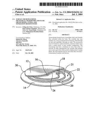
[0024] FIG. 1 is a schematic perspective illustration of a
partial cutaWay of a spiral micropump;
[0025] FIG. 2 is an exemplary spiral micropump coupled
to a typical electrostatic comb drive system for supplying
rotational motion to the micropump;
[0026] FIG. 3 is a cross-sectional vieW of the spiral
micropump of FIG. 2;
[0027] FIG. 4 is a picture of a spiral micropump expelling
a droplet of ?uid under experimental conditions;
[0028] FIG. 5(a) is a cross-sectional vieW of spiral micro
pump of FIG. 2;
[0029] FIG. 5(b) is a detail vieW of a portion of the spiral
micropump of FIG. 5(a);
[0030] FIG. 6(a) is a top vieW of the spiral micropump of
FIG. 2 including a housing seal;
[0031] FIG. 6(b) is a cross-sectional vieW taken at section
line A-A in FIG. 6(a);
[0032] FIG. 6(a) is a cross-sectional vieW taken at section
line B-B in FIG. 6(b);
[0033] FIG. 6(LD is a detail vieW of a portion of the spiral
micropump shoWn in FIG. 6(a);
[0034] FIG. 7 is a schematic illustration of a crescent
micropump;
[0035] FIG. 8 is a picture of tWo exemplary crescent
micropumps, the micropump on the left side having a top
cover and the micropump on the right side Without a top
cover;
[0036] FIG. 9 is a cross section of the crescent micropump
of FIG. 7;
[0037] FIG. 10 is a schematic illustration of a planetary
gear micropump;
[0038] FIG. 11 is a collection of schematic illustrations of
the micropump of FIG. 10 in various orientations during
operation;
11. US 2004/0126254 A1
[0039] FIG. 12(a) is a cross-sectional top vieW of a Von
Karman micropump;
[0040] FIG. 12(b) is a cross-sectional front vieW of the
Von Karman micropump of FIG. 12(a); and
[0041] FIG. 13 is a cross-sectional top vieW of a centrifu
gal micropump.
DETAILED DESCRIPTION OF THE
INVENTION
[0042] This invention includes numerous embodiments of
monolithic micropumps that are capable of pumping ?uids
and are con?gured for use in microelectromechanical sys
tems (MEMSs). These micropumps are monolithic struc
tures having thicknesses of no more than about 12 microns
and include pumping chambers With inlets and outlets, and
structures for mechanically urging ?uid from the inlet to the
outlet. As used herein, the term monolithic refers to the
resulting structure obtained from an integrated circuit for
mation process, Which generally comprises a plurality of
lithography, etching, and deposition steps. Thus, no assem
bly steps, such as bonding steps, are needed as the various
layers are inherently self-assembled. Although the micro
pumps according to the invention are fully monolithic, use
of this term does not preclude substantially free movement
of one layer relative to another layer, such as in the case of
a spinning rotatable disk.
[0043] Micropumps according to the invention have a total
thickness of no more than about 12 microns. Thicknesses of
the micropumps described herein are less than the thick
nesses of conventional pieZoelectric driven membrane
pumps having, Which have thicknesses of betWeen about 80
microns and about 100 microns. The relatively high ef?
ciency of pumps having thicknesses of 12 microns or less is
an unexpected result because as the thickness is reduced to
no more than 12 microns, the Reynolds number decreases
and the effective viscosity increases. Therefore, it Would be
expected that the loW Reynolds number Would render pumps
according to the invention ineffective. HoWever, it has been
found for thickness of no more than about 12 microns, that
viscous effects actually begin aiding pumping as the mecha
nism for pumping is based on viscous drag and not on
inertial effects.
[0044] Embodiments of these micropumps, Which are
described in detail beloW, include viscous micropumps
formed from rotatable discs and ring gear micropumps. The
viscous micropumps include a spiral micropump, a Von
Karman micropump, Which is a spiral micropump Without a
spiral protrusion, and a centrifugal micropump. The ring
gear micropumps include a crescent micropump and a
planetary gear micropump. The micropumps may be actu
ated electrostatically using on-chip micro-engines. Slightly
larger meso-scale versions of these pumps can be fabricated
using more conventional machining techniques and poWered
using small electric motors.
[0045] These micropumps may be used in a variety of
applications. For instance, these micropumps may be
included as a component of an integrated circuit system and
be placed in communication With microprocessors, ampli
?ers, actuators, voltage controllers for the actuators, sensors
and other appropriate devices. These micropumps may be
used as a component in microlabs, Which may also be
Jul. 1, 2004
referred to as a lab-on-a-chip, in medical devices, such as
insulin pumps, chemical synthesis, for cooling systems in
integrated circuits, and other applications.
[0046] Each of these embodiments is preferably formed
using surface machining processes capable of fabricating
hundreds or thousands of devices together With no part
assembly being required. Surface micromachined devices
are planar in nature, and are characteriZed by very shalloW
depths, such as, but not limited to, no more than about 12
microns. The micropumps may be fabricated using Sandia
National Laboratories’ Ultraplanar Multi-level MEMs Tech
nology (SUMMiTTM) process or similar process. The SUM
MiTTM process uses three or four movable polysilicon layers
together With one stationary polysilicon layer (“Poly”). The
polysilicon layers are separated from adjacent layers by
sacri?cial oxide layers that are removed during the ?nal etch
release process step. See eg I-C Compatible Polysilicon
Surface Micromachining by J. J. SniegoWski and M. P. de
Boer, Annu. Rev. Mater. Sci. 2000, 30:299-333.
[0047] 1. Monolithic Viscous Micropumps
[0048] A. Spiral Micropump
[0049] One embodiment of this invention, as shoWn in
FIG. 1 and referred to hereinafter as the spiral micropump,
includes a rotatable disk 12 coupled to a stationary plate 14
using a pin joint 16, Which is positioned generally Within the
center of stationary plate 14. Rotatable disk 12 includes a
spiral protrusion 21 that directs ?uids from an inlet port 18
to an outlet port 20. Stationary plate 14 is a generally ?at
shaped component and includes tWo generally ?at surfaces.
One of these ?at surfaces is positioned in close proximity to
spiral protrusion 21. In one embodiment, the combined
thickness of rotatable disk 12, stationary plate 14, and spiral
protrusion 21 is no more than about 12 microns. In at least
one embodiment, the spiral micropump may be formed from
as feW as 2 silicon layers. HoWever, the sprial micropump
may be formed from betWeen 3 and 5 silicon layers as Well.
[0050] In another embodiment, the micropump contains
the components described above; hoWever, spiral protrusion
21 is not included. Rather, this embodiment, Which is
referred to as a viscous micropump, pumps ?uids using
viscous phenomena as the driving mechanism.
[0051] During operation, a ?uid enters inlet port 18 and
?oWs through spiral channel 22 to outlet port 20. Spiral
channel 22 is formed by spiral protrusion 21 that is bounded
by stationary plate 14 on one side and rotatable disk 12 on
the other side. Fluids, With or Without suspended particles,
are draWn through spiral channel 22 as a result of a velocity
pro?le created by rotatable disk 12 rotating around pin joint
16. The velocity pro?le consists of ?uids having velocities
that vary betWeen about Zero at the surface of stationary
plate 14 and a velocity approximately equal to the rotational
velocity of the rotatable disk at a location proximate to the
inner surface 24 of rotatable disk 12. Viscous stresses on
upper surfaces of the spiral channel 22 alloW ?uids to be
transported against an imposed pressure difference. The
spiral micropump is capable of expelling a suf?cient amount
of ?uids to produce droplets of ?uid visible to the unassisted
human eye, as shoWn in FIG. 4.
[0052] Rotatable disk 12 may be rotated through numer
ous methods. In one embodiment, rotatable disk 12 is rotated
using an electrostatic comb drive microengine, as shoWn in
12. US 2004/0126254 A1
FIG. 2, that provides continuous mechanical power trans
mitted to rotatable disk 12 through a transmission 26, Which
may be a torque ampli?cation gear mechanism operating at
12:1. Transmission 26 includes an output gear 28 that
includes a plurality of teeth positioned on a perimeter 30 of
output gear 28. The teeth on output gear 28 mesh With the
teeth located on the perimeter 30 of rotatable disk 12.
[0053] FIG. 3 is a cross-sectional vieW of the spiral
micropump taken through the centerline to illustrate the
relationships betWeen the layers forming the spiral micro
pump. Rotatable disk 12 is formed from a polysilicon layer,
Which is identi?ed as Poly 4, and stationary plate 14 is
formed from another polysilicon layer, Which is identi?ed as
Poly 0. Spiral protrusion 21 is formed from three polysilicon
layers, Which are identi?ed as Poly 1, Poly 2, and Poly 3, and
is anchored to rotatable disk 12. This con?guration leaves a
small gap betWeen spiral protrusion 21 and stationary plate
14.
[0054] The spiral micropump may be contained using a
variety of seals or components for preventing ?uids from
leaking out. In one embodiment, seal 32 resembles a laby
rinth seal positioned around the periphery of the spiral
micropump, as shoWn in FIG. 5. The seal 32 can be formed
from three polysilicon layers. In one embodiment, the three
layers may be concentric and cylindrical. HoWever, the
layers are not limited to this shape or number. Rather, seal
32 may be formed from any other number of layers or
alternative shapes.
[0055] The three layers are positioned betWeen the rotat
able disk and the ?xed plate. The inner and outer layers form
protrusion extending from the stationary plate 14 and Poly
0, and the middle layer forms a protrusion extending from
the rotatable disk 12 and Poly 4 and positioned betWeen the
protrusions extending from the stationary plate 14. The
middle layer rotates With the rotatable disk 12. A small
clearance gap is located betWeen adjacent layers. As shoWn
in FIG. 5, the three cylindrical layers are de?ned by inter
connected layers designated as Poly 1, Poly 2, and Poly 3.
[0056] In another embodiment, as shoWn in FIG. 6, seal
32 may be a housing that nearly entirely encloses rotatable
disk 12, stationary plate 14, and spiral protrusion 21, except
for a small opening through Which transmission 26 contacts
rotatable disk 12. FIG. 6(b) is a cross-sectional vieW of the
spiral micropump and shoWs seal 32 formed from a top
cover 36 that is formed from a Poly 4 layer, a side Wall 38
that is formed from Poly 1, Poly 2 and Poly 3 layers, and a
bottom cover 40 that is formed from a Poly 0 layer. Top
cover 36 and side Wall 38 form a closed chamber that
surrounds rotatable disk 12 and stationary plate 14. In this
embodiment, spiral protrusion 21 is de?ned by the Poly 1
and 2 layer and is attached to rotatable disk 12. The Poly 1
layer may also include dimples that create protrusions beloW
the spiral protrusion 21 to improve the seal betWeen the poly
layers forming spiral protrusion 21. Seal 32 may further
include a cantilever seal 42, as shoWn in FIG. 6(a) for
reducing leakage from the bottom of pumping chamber 44
through an opening. Seal 32 may also include a dimple 48,
Which may be formed by a dimple cut in the Poly 3 layer, for
minimiZing leakage from the top of pumping chamber 44
through a WindoW.
[0057] Micropumps according to the invention may also
be used to lyse cells by pumping a cellular solution at a shear
Jul. 1, 2004
rate sufficient to destroy the cell membrane. In addition, the
shear ?eld created in the spiral or viscous micropumps can
be used to spatially separate constituents as the constituents
are eluted from the micropump.
[0058] In operation, a liquid containing cells is introduced
at the inlet 18 of the spiral or viscous micropump. As the
rotatable disk 12 is turned rapidly, the solution is pumped
toWards outlet 20, and a shear ?eld is developed betWeen
rotatable disk 12 and stationary plate 14 that is proportional
to the velocity of the rotating disk. If the resulting shear
stress induced in the cells in solution is high enough, the cell
membrane of the cells Will rupture, Which results in lysis of
the cells. After the cells rupture, the ?uid stream Will
continue to be pumped out of spiral channel 22 through
outlet 20. Cellular constituents, such as DNA and cell
membrane material, may be separated While ?oWing through
spiral channel 22, as described in detail beloW.
[0059] The shear ?eld developed by a viscous micropump
may be used to separate constituents in a ?uid stream
?oWing through a channel fed by the pump. Separation of
the constituents is possible due to a variation in velocity of
the ?uid across the ?uid stream. In the simplest case, the
?uid near rotatable disk 12 is moving at approximately the
velocity of the rotatable disk 12, and the ?uid near the
stationary plate 14 has a velocity approximately equal to
Zero, Which is the velocity of stationary plate 14. The
velocity varies linearly betWeen Zero and the moving disk
velocity as the ?uid stream is traversed from the stationary
plate to the rotatable disk. Because the flow ?eld through
channel 22 is essentially laminar, constituents stay in layers,
or lanes, as the constituents move through the micropump.
The constituents closest to rotatable disk 12 are expelled
from the micropump ahead of the sloWer moving constitu
ents that are located closer to stationary plate 14. Because of
this phenomena, constituents are separated in space and time
in an exit channel as a result of the constituents occupying
different layers Within the ?uid ?oW. The separation betWeen
constituents may be increased by increasing the speed of the
micropump. For best operation, different constituents should
be positioned at different locations across channel 22 in the
How stream. In some cases, such a constituent con?guration
occurs naturally because of the shear ?eld. Different con
stituents occupy different lamina because of the Way the
constituents respond to the shear ?eld.
[0060] Constituents may also be positioned in different
?uid lamina using other methods.
[0061] For instance, an electrode or an array of electrodes
can be incorporated in stationary plate 14 to apply an electric
?eld consisting of alternating or direct current (AC or DC,
respectively), to the electrode or electrodes While rotatable
disk 12 is grounded. Rotatable disk 12 may be grounded
through the drive mechanism. This con?guration produces
an electric ?eld that is generally perpendicular to the direc
tion of ?uid ?oW. The solution constituents are positioned
differently Within the cross-stream ?eld and are therefore, in
different ?uid lamina. The position of the solution constitu
ents is dictated by the constituents’ electrophoretic or dielec
trophoretic properties. The electrophoretic properties deter
mine the DC signal response, and the dielectrophoretic
properties determine the AC signal response. Constituents
positioned in lamina nearest rotating disk 12, Which is the
ground, travel further through the micropump in a particular
time period than other ?uids.
13. US 2004/0126254 A1
[0062] Other methods of establishing cross-stream ?elds
include sedimentation processes in Which different speci?c
gravity constituents are positioned at different locations in a
cross-stream gravity ?eld, and chemical affinity processes,
Whereby a Wall of a micropump, Whether stationary or
rotating, is coated Which causes chemical constituents to be
adsorbed and removed from the ?uids at different rates.
Differences in diffusion coef?cients correlating With differ
ent constituents causes some separation of constituents but
also leads to broadening of the bands of eluted constituents
as the ?uids are expelled from the micropump, thereby
reducing resolution.
[0063] These separation effects can be enhanced When the
pump is operated against a pressure gradient, such as Where
the pressure at outlet 20 is greater than the pressure at inlet
18. This pressure gradient forces the ?uids against the ?oW
induced by rotatable disk 12. The ?uid near stationary plate
14 is more affected by the pressure gradient than the ?uid in
streamlines located near rotatable disk 12. If the pressure
gradient is sufficient, the ?uid near stationary plate 14 Will
be pushed backWard against the shear driven ?oW. This
causes the solution constituents to be separated more Widely
because While the ?uid near the stationary Wall is pushed
back toWards inlet 18 by the pressure gradient, solution
constituents near rotatable disk 12 are pulled in the usual
?oW direction.
[0064] While these processes produce constituent separa
tion, the same processes may also be used for constituent
mixing. Enhanced diffusion (dispersion) in the shear ?eld
occurs When the constituent concentration gradient across
the stream due to along stream convection reduces the
mixing time required. Another method of mixing constitu
ents is to stop the ?oW at outlet 20. In this embodiment, a
re-circulation system is established in Which the ?uids ?rst
travel through the micropump in the forWard direction along
rotatable disk 12 and then travel back along stationary plate
14 due to the pressure driven ?oW in the loW velocity
streamlines positioned closely to stationary plate 14. This
re-circulation region is an effective micro?uidic mixer.
[0065] B. Von Karman Micropump.
[0066] In another embodiment of this invention, a micro
pump, Which is referred to as a Von Karman micropump is
shoWn in FIGS. 12a and 12b. The Von Karman micropump
is composed of a rotatable plate 82 that rotates on top of a
parallel ?xed plate 84 about pin joint 85. A cavity 86 is
formed betWeen the disk 82 and the plate 84 and for
pumping the ?uid. The ?xed plate 84 has an inlet port 88 and
an outlet port (not shoWn). The viscous forces caused by the
rotating ?at disk 82 carry the ?uid from the inlet port 88 to
the outlet port.
[0067] FIG. 12b illustrates a Von Karman micropump that
may be formed using the SUMMiT-VTM process and may
have a thickness no more than about 12 microns. In at least
one embodiment, the Von Karman micropump may be
formed from as feW as 2 silicon layers. HoWever, the Von
Karman micropump may be formed from betWeen 3 and 5
silicon layers as Well. The ?xed plate 84 may be formed in
Poly 0 and the inlet port 88 and may be created by a Bosch
etch through the Wafer. The rotatable plate 82 may be formed
in the Poly 3 and may create a cavity 86 Whereby the
rotatable plate 82 is about six microns from the ?xed plate
84. The rotatable plate 82 may be driven using gear teeth on
Jul. 1, 2004
the outer surface of the rotatable plate 82. The Poly 4 layer
may form a top cover 90 that may be connected seamlessly
to the housing Walls 92, Which may be anchored to the
ground. The housing Walls 92 and the Poly 4 top cover 90
provide a continuous seal around the entire micropump,
except for the area proximate to the driving gears 94.
Surface tension forces prevent the ?uid in the micropump
from leaking through the very small gap proximate to the
drive gears 94.
[0068] C. Centrifugal Micropump
[0069] FIG. 13 shoWs yet another embodiment of a vis
cous drag micropump and is referred to as a centrifugal
micropump. The centrifugal micropump may have a thick
ness no more than about 12 microns. In at least one
embodiment, the centrifugal micropump may be formed
from as feW as 2 silicon layers. HoWever, the centrifugal
micropump may be formed from betWeen 3 and 5 silicon
layers as Well. The con?guration of the centrifugal micro
pump resembles the spiral micropump; hoWever, the cen
trifugal micropump does not include a spiral protrusion.
Rather, the centrifugal micropump includes a radial array of
vanes 96 attached to a rotatable disk 98. The rotatable disk
98 functions as an impeller of the centrifugal micropump.
[0070] 2. Monolithic Ring Gear Micropumps
[0071] A. Crescent Micropump
[0072] The invention also includes planar gear pumps,
such as the crescent micropump and the planetary gear
micropump, for pumping ?uids and for lysing cells. The
planar gear micropumps may have thicknesses no more than
about 12 microns. In at least one embodiment, the planar
gear micropump may be formed from as feW as 2 silicon
layers. HoWever, the planary gear micropump may be
formed from betWeen 3 and 5 silicon layers as Well. The
planar gears may be used to lyse cells, as described in detail
above, by pumping a cellular solution through the micro
pump. The crescent micropump, as shoWn in FIG. 7,
includes a ring gear 48 having a plurality of teeth on its outer
and inner surfaces. In at least one embodiment, the ring gear
48 may be formed from three or four layers of silicon and a
base layer 49 may be formed from one or more layers of
silicon. The teeth on the outer surface mesh With teeth on a
drive gear, and the teeth on the inner surface mesh With an
idler 52. In this con?guration, a drive gear rotates and causes
ring gear 48 to rotate, Which in turn causes idler 52 to rotate.
This action causes a ?uid to be draWn into interior aspects
of ring gear 48 from inlet 54 and expelled through outlet 56.
Idler 52 and ring gear 50 are kept in position With a crescent
diverter 58.
[0073] FIG. 8 depicts tWo crescent micropumps 51 and
53, micropump 51 having a top cover in place and micro
pump 55 having the top cover removed. The crescent
micropumps can be driven With torsional ratchet actuators
60, or other structure for providing rotational motion to
micropumps. Torsional ratchet actuators are independently
attached to transmissions 62 for applying rotational motion
to ring gears 48. The crescent micropump on the right may
have a cover installed using a post fabrication technique
such as, but not limited to, anodic bonding.
[0074] FIG. 9 depicts a cross-section of ring gear 48
including a seal 64 positioned around pumping chamber 66,
Which is formed as an integral part of ring gear 48. Seal 64
14. US 2004/0126254 A1
resembles a labyrinth seal and is formed from a dimple in the
Poly 1 layer. In addition, seal 64 includes a plurality of
rollers that are created using a pin joint process and act as
axial bearings that support the Walls of the seal during
rotation and thus minimize friction.
[0075] B. Planetary Gear Micropump
[0076] Yet another embodiment of this invention, as
shoWn in FIG. 10 and referred to hereinafter as a planetary
gear micropump, may be used to pump ?uids or lyse cells.
The planetary gear micropump may have a thickness no
more than about 12 microns. In at least one embodiment, the
planetary gear micropump may be formed from as feW as 2
silicon layers. HoWever, the planetary gear micropump may
be formed from betWeen 3 and 5 silicon layers as Well. The
micropump includes a ring gear 68 mechanically coupled to
a sun gear 70 using ?rst and second planetary gears, 72 and
74 respectively. Sun gear 70 pivots eccentrically around
pivot 76 that is not in the center point of sun gear 70. Ring
gear 68 drives the rotation of ?rst and second planetary gears
72 and 74 and sun gear 70. The diameter of the ?rst
planetary gear 72 is larger than the diameter of the second
planetary gear 74, or vice versa, and the sum of the diam
eters of sun gear 70 and ?rst and second planetary gears 72
and 74 is approximately equal to the pitch diameter of ring
gear 68. The ring gear 68 may be formed from three or more
layers of silicon. A base layer may be formed from one or
more layers of silicon.
[0077] Operation of the planetary gear micropump is
shoWn in FIG. 11. As ring gear 68 rotates, ?rst and second
planetary gears 72 and 74 rotate around sun gear 70.
Rotation of ?rst and second planetary gears 72 and 74
around sun gear 70 causes sun gear 70 to rotate because the
gap 78 betWeen the right side of sun gear 70 and the inner
Wall of ring gear 68 is smaller than the gap 80 betWeen the
left side of sun gear 70 and the inner Wall of ring gear 68.
As sun gear 70 rotates around pivot 76, gap 78 continues to
shrink in siZe and sun gear is forced to make a full revolution
around pivot 76. This eccentric rotation of sun gear 70
produces successive increasing and decreasing volumes on
either side of sun gear 70 and the ?rst and second gears 72
and 74. Such action provides pumping action necessary for
the pump to operate.
[0078] The foregoing is provided for purposes of illustrat
ing, explaining, and describing embodiments of this inven
tion. Modi?cations and adaptations to these embodiments
Will be apparent to those skilled in the art and may be made
Without departing from the scope or spirit of this invention.
We claim:
1. A micropump, comprising:
a pumping chamber, Wherein said pumping chamber
includes an inlet for draWing ?uid therein and an outlet
for expelling said ?uid out of said chamber, and
structure for mechanically urging said ?uid from said inlet
to said outlet, Wherein said micropump is fully mono
lithic forming a monolithic body, said pump having a
total thickness of no more than about 12 microns.
2. The micropump of claim 1, Wherein said pumping
chamber includes at least one rotatable disc in ?uid com
munication With said ?uid, said structure for mechanically
urging comprising said rotatable disc.
Jul. 1, 2004
3. The micropump of claim 2, Wherein the at least one
rotatable disc comprises at least one protrusion extending
from the disc.
4. The micropump of claim 3, Wherein the at least one
protrusion forms a spiral shaped ?uid pathWay concentric
With the at least one rotatable disc.
5. The micropump of claim 3, Wherein the at least one
protrusion forms a plurality of radial vanes extending from
an axis of rotation of the rotatable disc.
6. The micropump of claim 2, Wherein at least one
rotatable disc further comprises a plurality of gear teeth on
a side surface of the rotatable disc.
7. The micropump of claim 6, further comprising at least
one crescent shaped diverter positioned in the pumping
chamber proximate to the at least one rotatable disc, and
Wherein an inner surface of the monolithic body includes a
plurality of gear teeth for meshing With the at least one
rotatable disc.
8. The micropump of claim 2, further comprising at least
one cap forming a portion of the monolithic body and having
an opening enabling a driving gear to contact the at least one
rotatable disc contained in the monolithic body.
9. The micropump of claim 2, further comprising a
labyrinth seal formed from a ?rst protrusion forming a ring
extending generally vertically from a base layer and sur
rounding the rotatable disc, a second protrusion forming a
ring extending generally vertically from the base layer and
positioned inside the ?rst protrusion, and a third protrusion
forming a ring extending generally vertically from the at
least one rotatable disc and positioned betWeen the ?rst and
second prostrusions.
10. The micropump of claim 2, further comprising at least
one electrostatic comb drive for rotating the at least one
rotatable disc.
11. The micropump of claim 10, further comprising at
least one gear in contact With the electrostatic comb drive
and in contact With the at least one rotatable disc.
12. The micropump of claim 11, Wherein the at least one
gear comprises a 12:1 torque ampli?cation gear train.
13. The micropump of claim 1, Wherein said pumping
chamber includes at least tWo rotatable gears therein, said
structure for mechanically urging comprising said rotating
gears.)
14. The micropump of claim 13, Wherein the at least tWo
rotatable gears comprises at least three rotatable gears,
Wherein a ?rst rotatable gear is rotatably attached to a pin
substantially at a center point of the base layer and includes
a plurality of gear teeth, a second rotatable gear including a
plurality of teeth on a side surface is positioned betWeen the
?rst rotatable disc and a side Wall of the monolithic body,
and a third rotatable gear including a plurality of teeth on a
side surface and having a diameter larger then the second
rotatable gear is positioned betWeen the ?rst rotatable gear
and a side Wall of the monolithic body.
15. A micropump, comprising:
a monolithic body formed from betWeen about tWo layers
of silicon and about ?ve layers of silicon and having a
thickness no more than about 12 microns, Wherein the
monolithic body comprises a base layer and side Walls
forming an pumping chamber containing at least one
rotatable disc; Wherein said pumping chamber includes
an inlet for draWing ?uid therein and an outlet for
expelling said ?uid out of said cavity; and
15. US 2004/0126254 A1
at least one rotatable disc positioned in the pumping
chamber for drawing a ?uid through the inlet and
expelling the ?uid out of the outlet.
16. The micropump of claim 15, Wherein the at least one
rotatable disc comprises at least one protrusion extending
from the disc.
17. The micropump of claim 15, Wherein the at least one
protrusion forms a spiral shaped ?uid pathWay concentric
With the at least one rotatable disc.
18. The micropump of claim 15, Wherein the at least one
protrusion forms a plurality of radial vanes extending from
an axis of rotation of the rotatable disc.
19. The micropump of claim 15, Wherein at least one
rotatable disc further comprises a plurality of gear teeth on
a side surface of the rotatable disc.
20. The micropump of claim 19, further comprising at
least one crescent shaped diverter positioned in the pumping
chamber proximate to the at least one rotatable disc, and
Wherein an inner surface of the monolithic body includes a
plurality of gear teeth for meshing With the at least one
rotatable disc.
21. The micropump of claim 15, Wherein the at least one
rotatable disc comprises at least three rotatable discs,
Wherein a ?rst rotatable disc is rotatably attached to a pin
substantially at a center point of the base layer and includes
a plurality of gear teeth, a second rotatable disc including a
plurality of teeth on a side surface is positioned betWeen the
?rst rotatable disc and a side Wall of the monolithic body,
and a third rotatable disc including a plurality of teeth on a
side surface and having a diameter larger then the second
rotatable disc is positioned betWeen the ?rst rotatable disc
and a side Wall of the monolithic body.
22. The micropump of claim 15, further comprising at
least one cap forming a portion of the monolithic body and
having an opening enabling a driving gear to contact the at
least one rotatable disc contained in the monolithic body.
23. The micropump of claim 15, further comprising a
labyrinth seal formed from a ?rst protrusion forming a ring
extending generally vertically from the base layer and
surrounding the rotatable disc, a second protrusion forming
a ring extending generally vertically from the base layer and
positioned inside the ?rst protrusion, and a third protrusion
Jul. 1, 2004
forming a ring extending generally vertically from the at
least one rotatable disc and positioned betWeen the ?rst and
second prostrusions.
24. The micropump of claim 15, further comprising at
least one electrostatic comb drive for rotating the at least one
rotatable disc.
25. The micropump of claim 24, further comprising at
least one gear in contact With the electrostatic comb drive
and in contact With the at least one rotatable disc.
26. The micropump of claim 25, Wherein the at least one
gear has a 12:1 torque ampli?cation gear train.
27. A method of pumping ?uids, comprising:
rotating at least one rotatable disc positioned in a pumping
chamber of a miropump formed from a monolithic
body having a thickness no more than about 12 microns
and containing the at least one rotatable disc; Wherein
a ?uid is draWn through an inlet in the pumping
chamber and expelled from an outlet in the pumping
chamber.
28. The method of claim 27, Wherein rotating at least one
rotatable disc comprises rotating at least one disc comprising
at least one protrusion extending from the disc.
29. The method of claim 28, Wherein rotating at least one
rotatable disc having at least one protrusion extending from
the disc comprises rotating at least one disc having a spiral
shaped protrusion extending from the disc.
30. The method of claim 28, Wherein rotating at least one
rotatable disc having at least one protrusion extending from
the disc comprises rotating at least one disc having a spiral
shaped protrusion extending from the disc.
31. The method of claim 27, Wherein rotating at least one
rotatable disc is accomplished using at least one electrostatic
comb drive.
32. The method of claim 27, Wherein rotating at least one
rotatable disc drives at least one idler gear positioned in the
pumping chamber of the at least one rotatable disc.
33. The method of claim 27, Wherein rotating the at least
one rotatable disc comprises rotating at least three gears in
the pumping chamber.
* * * * *