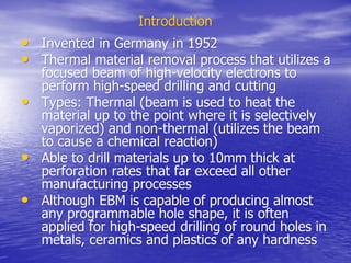
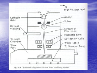
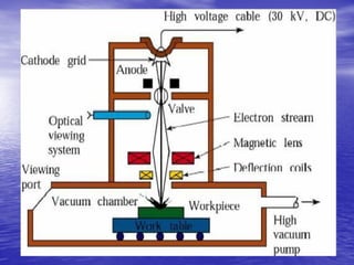
Electron Beam Machining (EBM) is a thermal material removal process that uses a focused beam of high-velocity electrons to perform high-speed drilling and cutting. It was invented in Germany in 1952. EBM utilizes an electron beam gun to generate, shape, and deflect an electron beam to drill or machine a workpiece. Key process parameters include beam current, pulse duration, lens current, and beam deflection signal, which control the energy delivered to the workpiece and characteristics of the drilled holes such as diameter and depth. EBM provides advantages such as high drilling speeds, ability to drill small holes, and no required mechanical contact force.
1. Electron beam machining uses a stream of high-speed electrons to drill precise holes in materials.
2. It has a high drilling rate of up to 4000 holes/second and can drill any material regardless of its properties.
3. The electron beam is controlled using electromagnetic lenses and magnetic deflection coils to focus the beam into a small spot and direct it in programmed patterns.
1. Electron beam machining uses a stream of high-speed electrons to drill precise holes in materials by melting or vaporizing the workpiece material.
2. It requires a vacuum chamber, electron beam gun to generate and shape the beam, and power supply to accelerate electrons up to 150kV.
3. The electron beam can be precisely focused and deflected using electromagnetic lenses and magnetic coils to drill holes as small as 0.1mm in diameter with an aspect ratio of 15:1.
This Presentation covers the basic concepts of EBW in a easy version. For more information, please refer the books mentioned in the references slide.... Thank you
Electron beam machining (EBM) uses a focused beam of electrons to melt and vaporize small amounts of material. It was invented in 1952 and works by accelerating electrons in a vacuum chamber to generate a small, high-energy spot that precisely removes material through melting and vaporization. Key aspects of EBM include its ability to machine very small, high aspect ratio holes and its minimal heat affected zone. However, it requires expensive equipment and vacuum conditions.
Electron beam machining (EBM) is a high-energy beam process invented in 1952 that uses an electron beam to remove material. Electrons are generated and accelerated to high velocities, focusing the beam into a small spot to intensely heat and melt or vaporize material. The process occurs inside a vacuum chamber to prevent electron scattering. Key parameters that control the machining include accelerating voltage, beam current, pulse duration and spot size. EBM can drill small, high aspect ratio holes and cut intricate shapes in a wide range of materials.
This document discusses electron beam machining (EBM), a thermal energy-based machining process. EBM works by accelerating electrons in a vacuum and focusing them into a beam that strikes and vaporizes small amounts of workpiece material. Key components of an EBM system include an electron gun, focusing lens, and deflector coil. Process parameters like beam current and spot size are controlled. EBM allows for precise micro-machining of hard, brittle, and electrically conductive materials but has high equipment costs and a slow material removal rate. Applications include drilling small holes in parts for industries like aerospace, electronics, and diesel engines.
Ultrasonic machining uses abrasive slurry and a vibrating tool to remove small chips of metal from a workpiece. It consists of an oscillator, transducer, tool, and slurry system. The oscillator converts electrical energy to high-frequency mechanical vibrations in the transducer. These vibrations are transmitted to the tool via the transducer cone and tool holder. As the tool vibrates at ultrasonic frequencies, abrasive particles in the slurry remove material from the workpiece through abrasion. The metal removal rate depends on factors like the abrasive grain size, material, slurry concentration, vibration amplitude, and frequency.
THERMAL AND ELECTRICAL BASED PROCESSESravikumarmrk
The document discusses various thermal energy based machining processes including EDM, EBM, LBM, and PAM. It provides details on the principles, specifications, and process parameters for EDM such as the use of a wire electrode, dielectric fluids, and circuit types. It also describes the principles of EBM using an electron beam, LBM using lasers, and PAM using ionized plasma gas. Key advantages and applications are highlighted for each process.
The document discusses various thermal energy based machining processes including EDM, laser beam machining, and plasma arc machining. It provides details on the principles, types, and process parameters for each. EDM works by producing sparks between an electrode and workpiece using a dielectric fluid, vaporizing small amounts of material. Laser beam machining uses a focused laser beam to melt and vaporize workpiece material. Plasma arc machining involves using a high-temperature ionized gas to cut and melt materials.
The document discusses various thermal energy based machining processes including EDM, laser beam machining, and plasma arc machining. It provides details on the principles, types, process parameters and applications of each process. EDM works by producing sparks between an electrode and workpiece using a dielectric fluid, vaporizing small amounts of material. Laser beam machining uses a focused laser beam to melt and vaporize material. Plasma arc machining involves heating a gas to an ionized plasma state and directing the plasma through a torch onto the workpiece.
Electric discharge machining (EDM) is a thermoelectric process that uses sparks produced by electric discharges to remove material from conductive workpieces. Short duration sparks erode material by melting and vaporizing small amounts from both the tool and workpiece electrodes. Effective dielectric flushing is needed to remove debris from the gap and improve machining accuracy and surface finish. Process parameters like voltage, current, pulse duration and frequency can be controlled to achieve different material removal rates and surface finishes for roughing and finishing operations. Common electrode materials include graphite, copper and brass due to their machinability and electrical conductivity.
Electron beam welding (EBW) is a fusion welding process in which a beam of high velocity electrons is directed to the materials being joined.The workpieces melts as the kinetic energy of the lectrons is transformed
into heat upon impact.
Electrochemical machining (ECM) is a non-traditional machining process that removes metal by electrochemical dissolution. It involves passing electrical current between an electrode tool and a metal workpiece submerged in an electrolyte solution. Positively charged metal ions dissolve from the workpiece and migrate to the cathode tool. ECM can machine any electrically conductive material regardless of hardness, strength or toughness. It produces complex shapes and cavities with high precision and no tool wear. However, ECM is limited to electrically conductive materials and generates acidic waste.
This document discusses the key characteristics of instruments used for measurement. It describes static characteristics like range, span, linearity, sensitivity and environmental effects. It also discusses dynamic characteristics and how instruments are modeled as generalized systems with inputs and outputs. Key static performance metrics are defined like systematic characteristics, hysteresis, resolution and drift over time. The document provides qualitative and quantitative definitions of these important instrument characteristics.
This document discusses the key characteristics of instruments used for measurement. It describes static characteristics like range, span, linearity, sensitivity and environmental effects that influence instrument performance. It also discusses dynamic characteristics and how the instrument output varies with rapid changes in the measured quantity. Key static characteristics discussed in more detail include drift over time, hysteresis and backlash.
NON CONVENTIONAL MACHINING PRESENTATIONKunal Chauhan
This document provides an overview of non-conventional machining processes including electron beam machining (EBM), laser beam machining (LBM), and ultrasonic machining (USM). EBM uses a focused beam of high velocity electrons to melt and evaporate material. LBM uses a high power laser beam capable of high power density to melt and evaporate material. USM uses a tool that vibrates at ultrasonic frequencies in an abrasive slurry to erode material away. Non-conventional machining processes allow machining of materials that are difficult to machine with conventional methods and provide benefits like higher accuracy, less heat impact, and ability to machine complex shapes.
The document discusses various welding processes and concepts. It provides information on:
1. Resistance welding which uses force and current through electrodes to generate heat and form a weld nugget between metal parts. No danger of electric shock as low voltage is used.
2. Features of resistance welding including no need for flux, clean worksite, easy automation, high production rates, and less heat affected area. Disadvantages include surface preparation needs and expensive equipment.
3. Ultrasonic welding which uses high frequency vibration to melt and fuse thermoplastic materials. It has a fast process, quick drying time, easy automation, and clean precise joints. Limitations are joint size and high tooling
Electrochemical machining (ECM) is a non-traditional machining process that removes metal by electrolysis rather than mechanical forces. In ECM, a tool acts as a cathode and the workpiece as an anode, and an electric current is passed through an electrolyte in the gap between them, chemically dissolving metal from the workpiece. ECM can machine hard metals and complex shapes more accurately than traditional machining. It provides a smooth surface finish with no mechanical forces or heat affecting the workpiece material. However, ECM requires an electrolyte solution, specialized equipment, and produces chemical waste, making it more expensive and less environmentally friendly than other processes.
The document summarizes the key components and functioning of an X-ray machine. The primary components are the X-ray tube, which contains a cathode that emits electrons and an anode target, and the power supply. The tube is housed within a tube head mounted on an arm, allowing it to be positioned. Electrons are emitted from the cathode filament and accelerated towards the anode target, where their energy is converted to X-rays. The power supply provides low voltage to heat the filament and high voltage of 60,000-120,000V between the cathode and anode to produce X-rays. Factors like tube voltage, current, filtration, exposure time and collimation control the X-
Electron beam welding uses a beam of electrons accelerated by high voltage to melt and join materials. It can achieve deep penetration with minimal heat input. It produces a clean, homogeneous weld in a vacuum environment without filler metals or shielding gas. However, it requires expensive equipment and a vacuum chamber. Laser beam welding uses a focused laser beam to melt materials. It has high travel speeds but requires precise part fit-up and tracking. Solid state welding joins materials without melting through processes like friction, diffusion, or ultrasonic welding. Plasma welding uses an arc struck in an externally-supplied ionized gas to produce high temperature for welding metals. Explosion welding joins materials through high velocity impact using a chemical explosion.
Electron beam welding uses a beam of electrons accelerated by high voltage to melt and join materials. It can achieve deep penetration with minimal heat input. It produces a clean, homogeneous weld in a vacuum environment without filler metals or shielding gas. However, it requires expensive equipment and a vacuum chamber. Laser beam welding uses a focused laser beam to melt materials. It has high travel speeds but requires precise part fit-up and positioning. Solid state welding joins materials without melting through processes like friction, diffusion, or ultrasonic welding. This reduces heat effects but is limited in applications. Plasma welding uses an arc struck in an externally-supplied ionized gas to produce high temperature for welding metals.
Atomic emission spectroscopy is a standard method for metal analysis where a sample is vaporized to form free atoms that are excited to higher energy states. When the atoms return to lower states, they emit photons of radiation. Modern instruments use non-combustion plasma sources like inductively coupled plasma. An atomic emission spectrometer consists of a sample atomizer, monochromator, and detector. The sample is vaporized and excited, then the emitted light is dispersed and measured to identify elemental composition. Atomic emission spectroscopy is used for applications like pharmaceutical and metals analysis, and determining mineral composition in materials.
Electron beam machining by Himanshu VaidHimanshu Vaid
Electron beam machining (EBM) is a thermal process that uses a focused beam of high-velocity electrons to perform high-speed drilling and cutting. It works by melting and rapidly vaporizing materials using the intense heat from electrons. The process requires specialized equipment that generates an electron beam through thermionic emission, accelerates the electrons, focuses the beam using electromagnetic lenses, and performs beam deflection inside a vacuum chamber to machine a workpiece. EBM can drill very small, high-aspect ratio holes at high speeds in almost any material without mechanical forces. However, it has high capital costs and requires regular maintenance of the vacuum systems.
Electrochemical micromachining (EMM) is a non-traditional machining process that uses electrical and chemical energy for precision micro-machining of conductive materials. EMM involves anodic dissolution of workpiece material in an electrolyte solution between a tool electrode and workpiece electrode. EMM allows for machining of complex micro-scale geometries without thermal or mechanical stresses. The document describes the fundamentals, process parameters, applications and a demonstration EMM setup developed for micro-fabrication.
Non-traditional machining processes are used to manufacture complex precision parts. They use indirect energy like sparks, lasers, heat or chemicals instead of direct tool contact. This allows machining of hard materials with complex shapes. Some common non-traditional processes include electrical discharge machining (EDM), electrochemical machining (ECM), laser beam machining, and abrasive jet machining. These processes remove material using techniques like electrical sparks, electrolysis, focused laser beams or high pressure abrasive jets. Non-traditional machining provides benefits like high accuracy, improved surface finish, less tool wear and greater design flexibility compared to traditional machining.
A review on techniques and modelling methodologies used for checking electrom...nooriasukmaningtyas
The proper function of the integrated circuit (IC) in an inhibiting electromagnetic environment has always been a serious concern throughout the decades of revolution in the world of electronics, from disjunct devices to today’s integrated circuit technology, where billions of transistors are combined on a single chip. The automotive industry and smart vehicles in particular, are confronting design issues such as being prone to electromagnetic interference (EMI). Electronic control devices calculate incorrect outputs because of EMI and sensors give misleading values which can prove fatal in case of automotives. In this paper, the authors have non exhaustively tried to review research work concerned with the investigation of EMI in ICs and prediction of this EMI using various modelling methodologies and measurement setups.
Low power architecture of logic gates using adiabatic techniquesnooriasukmaningtyas
The growing significance of portable systems to limit power consumption in ultra-large-scale-integration chips of very high density, has recently led to rapid and inventive progresses in low-power design. The most effective technique is adiabatic logic circuit design in energy-efficient hardware. This paper presents two adiabatic approaches for the design of low power circuits, modified positive feedback adiabatic logic (modified PFAL) and the other is direct current diode based positive feedback adiabatic logic (DC-DB PFAL). Logic gates are the preliminary components in any digital circuit design. By improving the performance of basic gates, one can improvise the whole system performance. In this paper proposed circuit design of the low power architecture of OR/NOR, AND/NAND, and XOR/XNOR gates are presented using the said approaches and their results are analyzed for powerdissipation, delay, power-delay-product and rise time and compared with the other adiabatic techniques along with the conventional complementary metal oxide semiconductor (CMOS) designs reported in the literature. It has been found that the designs with DC-DB PFAL technique outperform with the percentage improvement of 65% for NOR gate and 7% for NAND gate and 34% for XNOR gate over the modified PFAL techniques at 10 MHz respectively.
Presentation of IEEE Slovenia CIS (Computational Intelligence Society) Chapte...University of Maribor
Slides from talk presenting:
Aleš Zamuda: Presentation of IEEE Slovenia CIS (Computational Intelligence Society) Chapter and Networking.
Presentation at IcETRAN 2024 session:
"Inter-Society Networking Panel GRSS/MTT-S/CIS
Panel Session: Promoting Connection and Cooperation"
IEEE Slovenia GRSS
IEEE Serbia and Montenegro MTT-S
IEEE Slovenia CIS
11TH INTERNATIONAL CONFERENCE ON ELECTRICAL, ELECTRONIC AND COMPUTING ENGINEERING
3-6 June 2024, Niš, Serbia
DEEP LEARNING FOR SMART GRID INTRUSION DETECTION: A HYBRID CNN-LSTM-BASED MODELgerogepatton
As digital technology becomes more deeply embedded in power systems, protecting the communication
networks of Smart Grids (SG) has emerged as a critical concern. Distributed Network Protocol 3 (DNP3)
represents a multi-tiered application layer protocol extensively utilized in Supervisory Control and Data
Acquisition (SCADA)-based smart grids to facilitate real-time data gathering and control functionalities.
Robust Intrusion Detection Systems (IDS) are necessary for early threat detection and mitigation because
of the interconnection of these networks, which makes them vulnerable to a variety of cyberattacks. To
solve this issue, this paper develops a hybrid Deep Learning (DL) model specifically designed for intrusion
detection in smart grids. The proposed approach is a combination of the Convolutional Neural Network
(CNN) and the Long-Short-Term Memory algorithms (LSTM). We employed a recent intrusion detection
dataset (DNP3), which focuses on unauthorized commands and Denial of Service (DoS) cyberattacks, to
train and test our model. The results of our experiments show that our CNN-LSTM method is much better
at finding smart grid intrusions than other deep learning algorithms used for classification. In addition,
our proposed approach improves accuracy, precision, recall, and F1 score, achieving a high detection
accuracy rate of 99.50%.
We have compiled the most important slides from each speaker's presentation. This year’s compilation, available for free, captures the key insights and contributions shared during the DfMAy 2024 conference.
Harnessing WebAssembly for Real-time Stateless Streaming PipelinesChristina Lin
Traditionally, dealing with real-time data pipelines has involved significant overhead, even for straightforward tasks like data transformation or masking. However, in this talk, we’ll venture into the dynamic realm of WebAssembly (WASM) and discover how it can revolutionize the creation of stateless streaming pipelines within a Kafka (Redpanda) broker. These pipelines are adept at managing low-latency, high-data-volume scenarios.
2. Synopsis
Synopsis
•
• Introduction
Introduction
•
• Principle
Principle
•
• Characteristics of EBM
Characteristics of EBM
•
• Equipment – gun construction
Equipment – gun construction
•
• Types of gun (vacuum system)
Types of gun (vacuum system)
•
• Beam control
Beam control
•
• Process parameters
Process parameters
•
• Advantages
Advantages
•
• Limitations
Limitations
•
• Applications
Applications
3. Introduction
Introduction
•
• Invented in Germany in 1952
Invented in Germany in 1952
•
• Thermal material removal process that utilizes a
Thermal material removal process that utilizes a
focused beam of high-velocity electrons to
perform high-speed drilling and cutting
•
• Types: Thermal (beam is used to heat the
Types: Thermal (beam is used to heat the
material up to the point where it is selectively
vaporized) and non-thermal (utilizes the beam
to cause a chemical reaction)
•
• Able to drill materials up to 10mm thick at
Able to drill materials up to 10mm thick at
perforation rates that far exceed all other
manufacturing processes
•
• Although EBM is capable of producing almost
Although EBM is capable of producing almost
any programmable hole shape, it is often
applied for high-speed drilling of round holes in
metals, ceramics and plastics of any hardness
4. Principle
Principle
•
• A stream of high-speed electrons impinges
A stream of high-speed electrons impinges
on the work surface whereby the kinetic
energy, transferred to the work material,
produces intense heating. Depending on
the intensity of the heat thus generated,
the material can melt or vaporize
5.
6.
7.
8.
9. Major components of the system
Major components of the system
•
• Three important elements of EBM system:
Three important elements of EBM system:
1.
1. Electron beam gun: Function is to generate, shape and deflect the
Electron beam gun: Function is to generate, shape and deflect the
electron beam to drill or machine the
electron beam to drill or machine the workpiece
workpiece
•
• The essential constituents of the electron gun are:
The essential constituents of the electron gun are:
•
• Cathode- source of the electrons
Cathode- source of the electrons
•
• Bias Grid- to control the no. of electrons and acts as a switch for
Bias Grid- to control the no. of electrons and acts as a switch for
generating pulses
generating pulses
•
• Anode- to accelerate the electrons
Anode- to accelerate the electrons
•
• Magnetic coil that functions as a magnetic lens, repels and shapes
Magnetic coil that functions as a magnetic lens, repels and shapes
the electron beam into a converging beam
•
• Tungsten diaphragm- removes stray electrons and cools the set-
Tungsten diaphragm- removes stray electrons and cools the set-
up
up
•
• Rotating slotting disks mounted directly below the gun exit
Rotating slotting disks mounted directly below the gun exit
opening to protect the EBM gun from metal spatter and vapor
•
• Light microscope- to view the machining area
Light microscope- to view the machining area
•
• Three magnetic coils : Magnetic lens, deflection coil and
Three magnetic coils : Magnetic lens, deflection coil and stigmator
stigmator
that are respectively used to focus the beam, small amount of
controllable beam deflection and to correct minor beam
aberrations and ensures a round beam at the
aberrations and ensures a round beam at the workpiece
workpiece
10. Major components of the system
Major components of the system
2.
2. Power supply: voltages of up to 150kV is generated to accelerate
Power supply: voltages of up to 150kV is generated to accelerate
the electrons;
the electrons;
•
• All power supply variables are controlled by a microcomputer
All power supply variables are controlled by a microcomputer
•
• To ensure process repeatability, the process variables are
To ensure process repeatability, the process variables are
monitored and compared with set-points by the power supply
computer. If a discrepancy arises, the operator is alerted
3.
3. Vacuum system and machining chamber:
Vacuum system and machining chamber:
•
• A vacuum chamber is required for EBM and should have a volume
A vacuum chamber is required for EBM and should have a volume
of at least 1
of at least 1m
m3
3
to minimize the chance of spatter sticking to the
chamber walls
chamber walls
•
• Inside the chamber a positioning system is used for the controlled
Inside the chamber a positioning system is used for the controlled
manipulation of the
manipulation of the workpiece
workpiece
•
• The positioning system may be as simple as a single, motor-
The positioning system may be as simple as a single, motor-
driven rotary axis or as complex as a fully CNC, closed-loop, five-
axis system
axis system
11.
12.
13. Characteristics of EBM
Characteristics of EBM
•
• Important characteristic: high resolution and the long depth of field
Important characteristic: high resolution and the long depth of field
that is obtained because of the short wavelength of high energy
electrons;
electrons;
•
• Extraordinary energy (power densities of
Extraordinary energy (power densities of 10
106
6
kW/cm2 have been
kW/cm2 have been
achieved)
achieved)
•
• Ability to catalyze many chemical reactions, controllability and
Ability to catalyze many chemical reactions, controllability and
compatability
compatability with high vacuum
with high vacuum
•
• For conductive as well as non-conductive materials
For conductive as well as non-conductive materials
•
• At entry side of beam, a small burr
At entry side of beam, a small burr
•
• Workpiece
Workpiece material properties do not affect performance
material properties do not affect performance
•
• Small diameter holes (0.1 to 1.4mm)
Small diameter holes (0.1 to 1.4mm)
•
• Aspect ratio = 15:1
Aspect ratio = 15:1
•
• No mechanical force and hence fragile, thin, low strength
No mechanical force and hence fragile, thin, low strength
components can be easily machined
•
• Off-axis holes easily made
Off-axis holes easily made
•
• Residual thermal stresses generated on the
Residual thermal stresses generated on the workpiece
workpiece due to high
due to high
temperature gradient
•
• Very high investment cost
Very high investment cost
•
• Skilled operator is required
Skilled operator is required
•
• HAZ
HAZ
14. Types of vacuum system
Types of vacuum system
1.
1. High vacuum (HV)
High vacuum (HV)
2.
2. Medium vacuum (MV)
Medium vacuum (MV)
3.
3. Non vacuum (NV)
Non vacuum (NV)
•
• Still requires a high vacuum in the electron gun, but deliver the
Still requires a high vacuum in the electron gun, but deliver the
beam to a
beam to a workpiece
workpiece at atmospheric pressure, thus avoiding non-
at atmospheric pressure, thus avoiding non-
productive
productive pumpdown
pumpdown cycles completely
cycles completely
•
• Construction much different from the HV
Construction much different from the HV
•
• The beam path from the cathode consists of a series of
The beam path from the cathode consists of a series of
individually pumped stages that are all connected by small
apertures – this construction produces a pressure gradient that
ranges from atmospheric pressure to high vacuum
•
• Although NV system can increase productivity dramatically, they
Although NV system can increase productivity dramatically, they
are somewhat limited since the interaction of the electron beam
with air spreads and diffuses the beam thus lowering the power
density at the
density at the workpiece
workpiece – this results in an increase of the
– this results in an increase of the
thermal effects of the process, the effects are still far less than
those of conventional processes
•
• Standoff distance between the gun and the
Standoff distance between the gun and the workpeice
workpeice is limited to
is limited to
a maximum of 19mm
a maximum of 19mm
15.
16. Beam control
Beam control
•
• The electron beam is controlled with optical precision
The electron beam is controlled with optical precision
•
• The beam consists of negatively charged particles whose
The beam consists of negatively charged particles whose
energy content is determined by the mass and velocity
of the individual particles.
•
• The negatively charged particles can be accelerated in an
The negatively charged particles can be accelerated in an
electrostatic field to extreme high velocities. During the
process, the specific energy content of the electron
beam can be increased beyond the emission energy,
thus producing a beam of energy, the intensity of which
far exceeds that obtainable from light.
•
• Due to the precise electron optics, large amounts of
Due to the precise electron optics, large amounts of
energy can be manipulated with optical precision.
17. 1.
1. Electromagnetic lens:
Electromagnetic lens:
•
• Before the electrons collide with the
Before the electrons collide with the
workpiece
workpiece, a variable strength
, a variable strength
electromagnetic lens is used to refocus
the beam to any desired diameter down
to less than 0.025 mm at a precise
location on the
location on the workpiece
workpiece and thus
and thus
attains an extremely high power density.
•
• This extremely, high power density
This extremely, high power density
immediately vaporizes any material on
which the beam impinges.
18. 2.
2.Magnetic deflection coil:
Magnetic deflection coil:
•
• Mounted below the magnetic lens, is used to bend the
Mounted below the magnetic lens, is used to bend the
beam and direct it over the desired surface of the
workpiece
workpiece. This deflection system permits programming
. This deflection system permits programming
of the beam in any specific geometrical pattern, using
the proper deflection coil current input
•
• At the point of beam impingement, the kinetic energy in
At the point of beam impingement, the kinetic energy in
the beam is converted to thermal energy in
the beam is converted to thermal energy in workpiece
workpiece.
.
•
• Another interesting deflection control technique is the
Another interesting deflection control technique is the
flying spot scanner or optical tracing device. Using this
device, the electron beam can be deflected to cover
almost any conceivable pattern over a 0.25
almost any conceivable pattern over a 0.25 sq.in
sq.in. area.
. area.
The desired pattern is drawn, then photographed, and
the photographic negative acts as the master.
•
• The electron beam can also be deflected in a
The electron beam can also be deflected in a
predetermined pattern by a relay tray or a flying spot
scanner mounted in a control cabinet, which consists of
a saw-tooth square wave and sine wave generator. By
using this process, it is possible to drill a cross-shaped
hole.
hole.
19.
20. Process parameters
Process parameters
•
• Beam current, pulse duration, lens current and the beam
Beam current, pulse duration, lens current and the beam
deflection signal are the four important parameter
associated with EBM
associated with EBM
1.
1. Beam current:
Beam current:
•
• Continuously adjustable from approximately 100
Continuously adjustable from approximately 100µamp to
µamp to
1amp
1amp
•
• As beam current is increased, the energy per pulse
As beam current is increased, the energy per pulse
delivered to the
delivered to the workpiece
workpiece is also increased
is also increased
2.
2. Pulse duration:
Pulse duration:
•
• Affects both the depth and the diameter of the hole
Affects both the depth and the diameter of the hole
•
• The longer the pulse duration, the wider the diameter and
The longer the pulse duration, the wider the diameter and
the deeper the drilling depth capability will be
•
• To a degree, the amount of recast and the depth of HAZ
To a degree, the amount of recast and the depth of HAZ
will be governed by the pulse duration – shorter pulse
durations will allow less interaction time for thermal effects
to materialize
to materialize
•
• Typical EBM systems can generate pulses as short as 50µs
Typical EBM systems can generate pulses as short as 50µs
or as long as 10msec
21. Process parameters
Process parameters
3.
3. Lens current:
Lens current:
•
• Determines the distance between the focal point and the
Determines the distance between the focal point and the
electron beam gun (working distance) and also determines
the size of the focused spot on the
the size of the focused spot on the workpiece
workpiece
•
• The diameter of the focused electron beam spot on the
The diameter of the focused electron beam spot on the
workpiece
workpiece will, in turn, determine the diameter of the hole
will, in turn, determine the diameter of the hole
produced
produced
•
• The depth to which the focal point is positioned beneath the
The depth to which the focal point is positioned beneath the
workpiece
workpiece surface determines the axial shape of the drilled
surface determines the axial shape of the drilled
hole
hole
•
• By selecting different focal positions, the hole produced can
By selecting different focal positions, the hole produced can
be tapered, straight, inversely tapered or bell shaped
4.
4. Deflection coil:
Deflection coil:
•
• When the hole shapes are required to be other than round,
When the hole shapes are required to be other than round,
the beam deflection coil is programmed to sweep the beam
in the pattern necessary to cut out the shape at the hole’s
periphery
periphery
•
• Beam deflection is usually applicable only to shapes smaller
Beam deflection is usually applicable only to shapes smaller
than 6mm
than 6mm
22. Advantages
Advantages
•
• Very high drilling rates – up to 4000 holes/sec
Very high drilling rates – up to 4000 holes/sec
•
• Drills in many different configurations
Drills in many different configurations
•
• Drills any material - Hardness, thermal
Drills any material - Hardness, thermal capactiy
capactiy, ductility, electrical
, ductility, electrical
conductivity or surface properties (reflectivity) etc, are not barriers
•
• No mechanical distortion
No mechanical distortion
•
• Limited thermal effects because only one pulse is required to
Limited thermal effects because only one pulse is required to
generate each hole and pulse durations are short
•
• Computer controlled parameters
Computer controlled parameters
•
• High accuracy – capability to maintain high accuracy and repeatability
High accuracy – capability to maintain high accuracy and repeatability
±0.1mm for position of the hole and ±5% for the hole diameter
•
• Drilling parameters can easily be changed even during drilling of
Drilling parameters can easily be changed even during drilling of
single
single workpiece
workpiece from one to the other.
from one to the other.
•
• No tool wear
No tool wear
•
• Best obtainable finish, compared to the other unconventional
Best obtainable finish, compared to the other unconventional
processes used to drill precision holes
•
• Low operating cost
Low operating cost
23. Limitations
Limitations
•
• High capital equipment cost
High capital equipment cost
•
• Holes produced in materials of thickness
Holes produced in materials of thickness
>0.13mm are tapered. So can machine thinner
parts only
parts only
•
• Limited to 10mm material thickness
Limited to 10mm material thickness
•
• Requires vacuum – nonproductive pump down
Requires vacuum – nonproductive pump down
time
time
•
• Availability limited
Availability limited
•
• Presence of a thin recast layer which may be a
Presence of a thin recast layer which may be a
consideration in some applications
•
• High level of operator skill required
High level of operator skill required
•
• Necessity for auxiliary backing material
Necessity for auxiliary backing material
24. Applications
Applications
•
• High-speed perforations in any kind of material –
High-speed perforations in any kind of material –
fluid and chemical industries use EBM to produce a
multitude of holes for filters and screens
•
• Perforation of small diameter holes in thick
Perforation of small diameter holes in thick
materials
materials
•
• Drilling of tapered holes
Drilling of tapered holes
•
• Non-circular hole drilling
Non-circular hole drilling
•
• Engraving of metals, ceramics and
Engraving of metals, ceramics and vaporised
vaporised layers.
layers.
•
• Machining of the thin films to produce resistor
Machining of the thin films to produce resistor
networks in the IC chip manufacture
26. Glass fiber spinning head drilled by EBM
Glass fiber spinning head drilled by EBM
Dome material: Cobalt alloy steel; wall thickness: 4.3 to
6.3mm; hole dia: 0.81mm;
11,766 holes drilled in 40mins; 100 times faster than EDM; 20
to 100 times faster than laser drilling
27. Dome material: chrome nickel cobalt molybdenum tungsten
steel; wall thickness: 1.1mm; hole dia: 0.9mm;
3800 holes drilled in 60mins