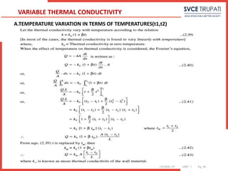
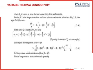
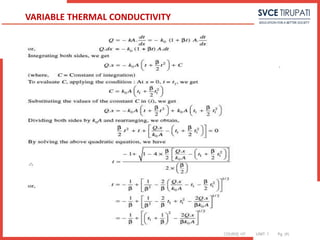
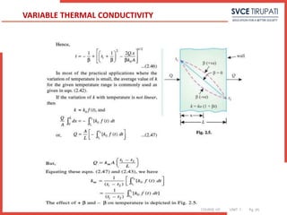
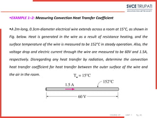
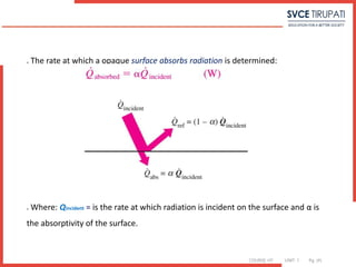
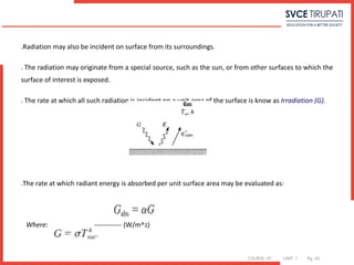
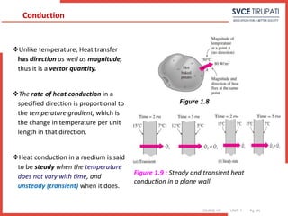
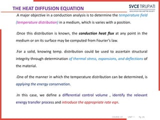
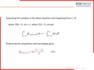
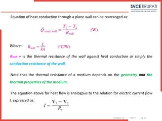
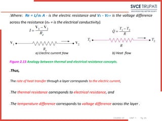
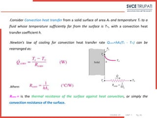
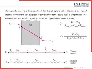
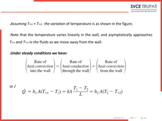
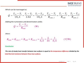
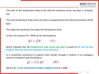
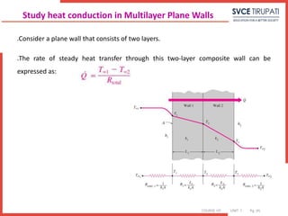
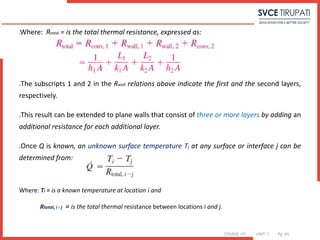
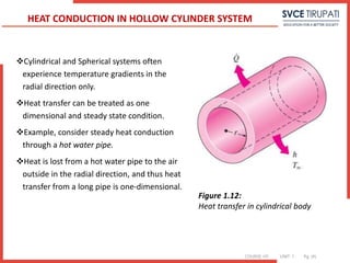
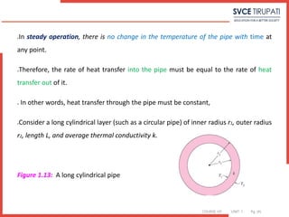
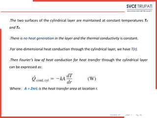
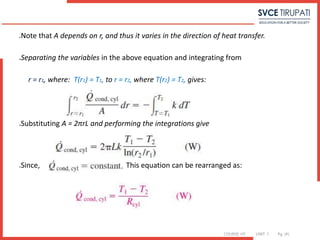
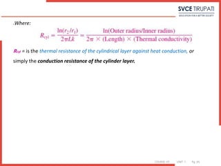
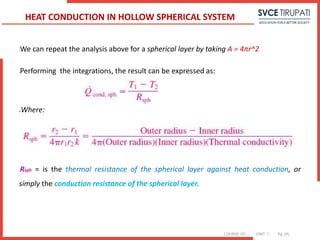
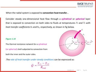
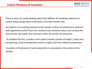
The document provides a comprehensive overview of heat transfer, covering its modes (conduction, convection, and radiation) and fundamental concepts including Fourier's Law and Newton's Law of Cooling. It elaborates on mathematical principles related to steady-state and transient heat conduction, as well as applications and examples relevant to real-life scenarios. Additionally, it discusses properties of materials affecting heat transfer, such as thermal conductivity and emissivity.


![COURSE: HT UNIT: 1 Pg. (#)
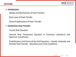
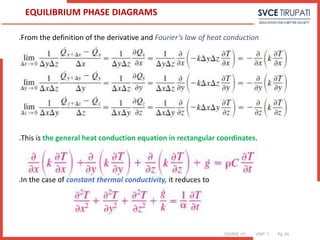
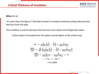
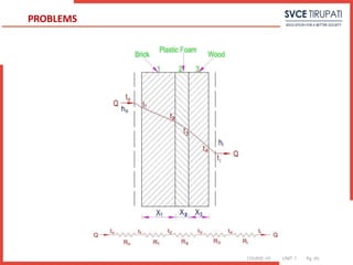
Q=Aha(Ta-T1) =-k1A(T2-T1 / L1)= -k2A(T3-T2 / L2)=-k3A(T4-T3 / L3) =Ahb(T4-Tb)
Q= (Ta-T1)/Ra = T1-T2 / R1 = T2-T3 / R2 = T3-T4 / R3 = T4-Tb / Rb
Where
Ra = 1/Aha, R1 = L1/Ak1, R2 = L2/Ak2, R3 = L3/Ak3, Rb = 1/Ahb
ΔT = Ta-Tb = (Ta-T1 )+(T1-T2)+(T2-T3)+(T3-T4)+(T4-Tb)
Q= ΔT/ΣR
Q= Ta-Tb / [1/haA+L1/Ak1+L2/Ak2+L3/Ak3+1/hbA ]
= Ta-Tb /ΣR
Heat conduction through composite wall](https://image.slidesharecdn.com/unitidigitalcontent-240709140328-864ee228/85/UNIT-I-Digital-Content-pptx-engineering-shshhsghsjsjsggh-70-320.jpg)
![COURSE: HT UNIT: 1 Pg. (#)
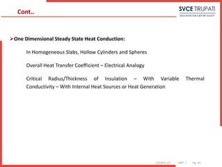
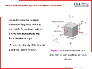
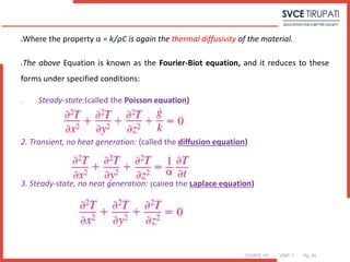
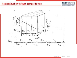
ΣR = 1/haA+L1/Ak1+L2/Ak2+L3/Ak3+1/hbA
ΣR =1/A[1/ha+L1/k1+L2/k2+L3/k3+1/hb]
Ta=T1, Tb=T4
R=1/UA, Q= Ta-Tb / 1/UA = Q=UAC(Ta- Tb)
U is the overall heat transfer coefficient
Heat conduction through composite wall](https://image.slidesharecdn.com/unitidigitalcontent-240709140328-864ee228/85/UNIT-I-Digital-Content-pptx-engineering-shshhsghsjsjsggh-71-320.jpg)
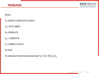
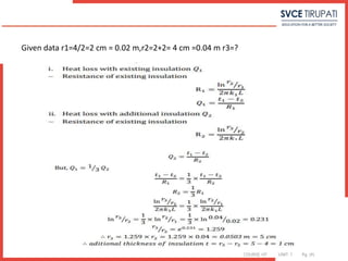
![COURSE: HT UNIT: 1 Pg. (#)
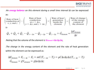
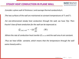
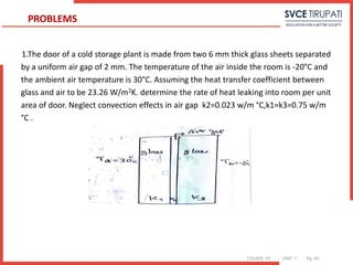
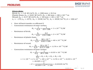
Given data
L1 = 6mm
L2 = 2 mm
L3 = 6 mm
Ta = 30°C
Tb = -20°C
ha =hb = 23.36 W/m2 K
Q/A = Ta-Tb/ [1/ha+L1/k1+L2/k2+L3/k3+1/hb ]
Q/A = 30 – (- 20) / [1/23.26+ 0.006/0.75 + 0.002/0.02 + 0.006/0.75+1/23.26]
Q/A = 247.5 W/m2
PROBLEMS](https://image.slidesharecdn.com/unitidigitalcontent-240709140328-864ee228/85/UNIT-I-Digital-Content-pptx-engineering-shshhsghsjsjsggh-73-320.jpg)
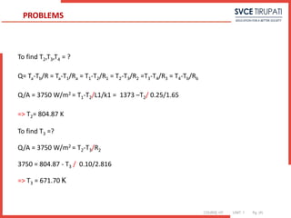
![COURSE: HT UNIT: 1 Pg. (#)
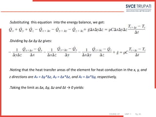
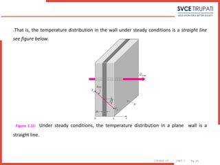
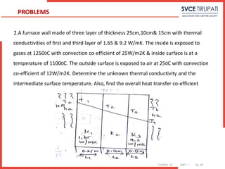
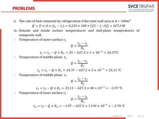
Heat Transfer
Q=haA(Ta-T1)
Q/A = 3750 W/m2
Q= ΔT/ΣR
Q/A= Ta-Tb/ [1/ha+L1/k1+L2/k2+L3/k3+1/hb ]
3750 = 1523 – 298 / [1/25 + 0.25/1.65 + 0.10/k2+ 0.15/9.2+1/12]
k2 = 2.816 W/mK
PROBLEMS](https://image.slidesharecdn.com/unitidigitalcontent-240709140328-864ee228/85/UNIT-I-Digital-Content-pptx-engineering-shshhsghsjsjsggh-76-320.jpg)
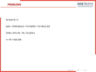
![COURSE: HT UNIT: 1 Pg. (#)
U= 1/R
R = [1/ha+L1/k1+L2/k2+L3/k3+1/hb ]
=[1/25 + 0.25/1.65 + 0.10/ 2.816 + 0.15/9.2+1/12]
= [0.04+1.9+2.916+0.016+0.08]
= 0.3258 K/W
U= 1/R = 3.069 W/K
PROBLEMS](https://image.slidesharecdn.com/unitidigitalcontent-240709140328-864ee228/85/UNIT-I-Digital-Content-pptx-engineering-shshhsghsjsjsggh-77-320.jpg)

![COURSE: HT UNIT: 1 Pg. (#)
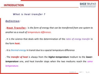
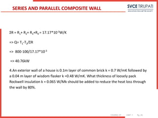
R1= L1/k1A1 = 0.05/50*1 = 1*10-3W/K
=> R2 = 1/[ 1/Rb+ 1/Rc ]
Rb= Lb/kbAb = 0.1/10*0.5 = 2*10-2W/K
Rc= Lc/kcAc = 0.1/6.67*0.5 = 3*10-2W/K
=> R2 = 1/[ 1/2*10-2 + 1/3*10-2] = 1.2*10-2W/K
=> R3 = L3/k3A3 = 0.05/20*1 = 2.5*10-3W/K
=> R4 = L4/k4A4 = 0.05/30*1 = 1.66*10-3W/K
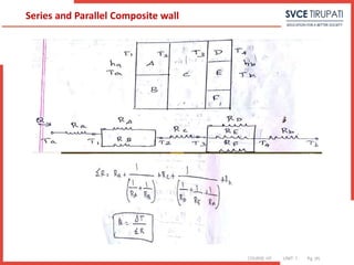
SERIES AND PARALLEL COMPOSITE WALL](https://image.slidesharecdn.com/unitidigitalcontent-240709140328-864ee228/85/UNIT-I-Digital-Content-pptx-engineering-shshhsghsjsjsggh-82-320.jpg)
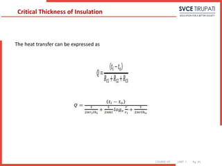
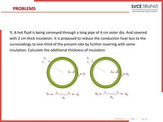
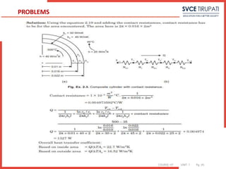
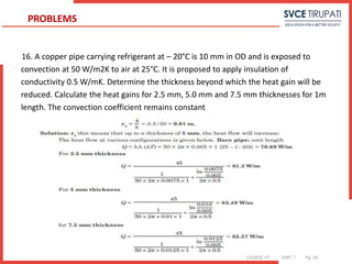
![COURSE: HT UNIT: 1 Pg. (#)
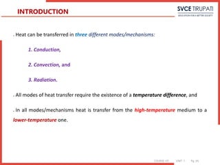
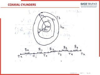
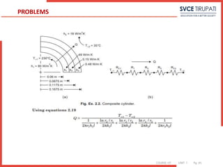
Q = ha 2¶r1L (Ta-T1)
R =1/ 2¶ L [1/ har1 +1/k1 ln(r2/r1)+ 1/k2 ln(r3/r2)+1/k3 ln(r4/r3) + 1/ har4 ]
Q= ΔT/R
ΔT = Ta-Tb /R
Q = T1-T2 / 1/2 ¶ k1L1(lnr2/r1) = T2-T3 / 1/2 ¶ k2L2(lnr3/r2) = T3-T4 / 1/2 ¶ k3L3(lnr4/r3) =
T4-T3 / 1/2 ¶ k3L3(lnr4/r3) = T4-Tb / 1/hb (2¶r3L)
COAXIAL CYLINDERS](https://image.slidesharecdn.com/unitidigitalcontent-240709140328-864ee228/85/UNIT-I-Digital-Content-pptx-engineering-shshhsghsjsjsggh-85-320.jpg)
![COURSE: HT UNIT: 1 Pg. (#)
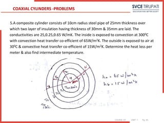
Given
ri = 10cm = 0.1m =r1
r2 = r1 + 0.025 = 0.125 m
r3 = r2 + 0.03 = 0.155 m
r4 = r3 + 0.035 = 0.19 m
k1 = 25 W/mK , ha = 65 W/m2K
K2 = 0.25 W/mK , hb = 15 W/m2K
K 3= 0.65 W/mK, L= 1m (if not given)
ΣR =1/ 2¶ L [1/ har1 +1/k1 ln(r2/r1)+ 1/k2 ln(r3/r2)+1/k3 ln(r4/r3) + 1/ har4 ]
ΣR = 0.268 W
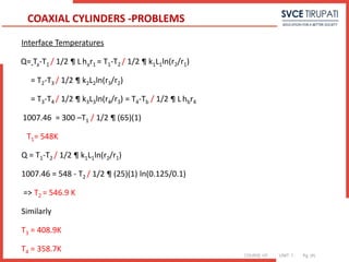
Q= ΔT/ ΣR = 300-30/ 0.268 = 1007.46 W/m
COAXIAL CYLINDERS -PROBLEMS](https://image.slidesharecdn.com/unitidigitalcontent-240709140328-864ee228/85/UNIT-I-Digital-Content-pptx-engineering-shshhsghsjsjsggh-87-320.jpg)
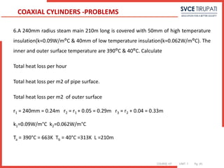
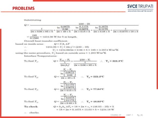
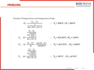
![COURSE: HT UNIT: 1 Pg. (#)
Q= ΔT/ ΣR
ΣR = 1/ 2¶ L [1/ har1 +1/k1 ln(r2/r1)+ 1/k2 ln(r3/r2)+1/k3 ln(r4/r3) + 1/ hbr4 ]
ΣR = 1/ 2¶ 210 [0 +1/0.09 ln(0.29/0.24)+ 1/0.062 ln (0.33/0.29)+0+0]
ΣR = 3.13*10-3°C/W
Q= ΔT/ ΣR = (663- 313)/ 3.13*10-3 =111.5kW
(i) Total heat loss per hour
Q= 111.5*103 / 1/ 3600 = 401.4 MJ/hr
(ii) Total heat loss per m2 of pipe surface
Q= 111.5*103 / 1/2 ¶*0.24*210 = 35.29 MJ/hr
(iii) Total heat loss per m2 of outer surface
Q= 111.5*103 / 1/2 ¶*0.33*210 = 48.52 MJ/hr
COAXIAL CYLINDERS -PROBLEMS](https://image.slidesharecdn.com/unitidigitalcontent-240709140328-864ee228/85/UNIT-I-Digital-Content-pptx-engineering-shshhsghsjsjsggh-90-320.jpg)
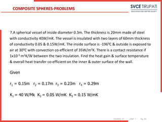
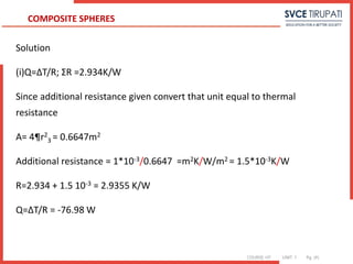
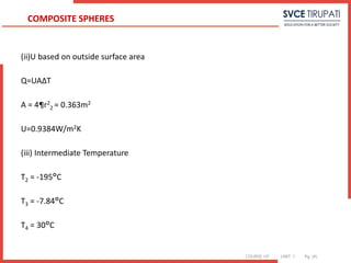
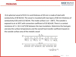
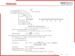
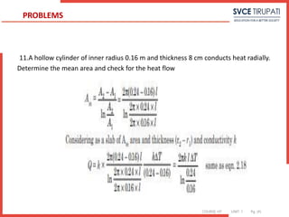
![COURSE: HT UNIT: 1 Pg. (#)
COMPOSITE SPHERES
R= ¼ ¶{ 1/hiri
2 +1/k1[1/r1 - 1/r2] +1/k2[1/r2 - 1/r3] +1/hor3
2}
Q= Ti-T0/4¶hiri
2 = T1-T2/ 1/4¶ [1/r1-1/r2] = T2-T3/ 1/4¶ [1/r2-1/r3]
= T3-T4/ 1/4¶ [1/r4-1/r3]
= T4-Tb /4¶hor3
2](https://image.slidesharecdn.com/unitidigitalcontent-240709140328-864ee228/85/UNIT-I-Digital-Content-pptx-engineering-shshhsghsjsjsggh-91-320.jpg)
![COURSE: HT UNIT: 1 Pg. (#)
11. A surface is at 200°C and has an area of 2m2. It exchanges heat with another
surface B at 30°C by radiation. The value of factor due to the geometric location and
emissivity is 0.46. Determine the heat exchange. Also find the value of thermal
resistance and equivalent convection coefficient.
Solution:
Given data T1 = 200°C = 200 + 273 = 473K, T2 = 30°C = 30 + 273 = 303K
σ = 5.67 × 10⁻⁸, A = 2m2, F = 0.46.
Q = 0.46 × 5.67 × 10–8 × 2[4734 – 3034] = 0.46 × 5.67 × 2 [(473/100)4 – (303/100)4]
Q = 2171.4 W
PROBLEMS](https://image.slidesharecdn.com/unitidigitalcontent-240709140328-864ee228/85/UNIT-I-Digital-Content-pptx-engineering-shshhsghsjsjsggh-102-320.jpg)
![COURSE: HT UNIT: 1 Pg. (#)
12. A electric room heater (radiator) element is 25 cm long and 4 cm in diameter. The
element dissipates heat to the surroundings at 1500 W mainly by radiation, the
surrounding temperature being 15°C. Determine the equilibrium temperature of the
element surface.
Solution
Given data L=25 cm, D= 4 cm, Q=1500W, T2=15+273=288 k
,Q = σ A(T1 4 – T2 4)
1500 = 5.67 × π × 0.04 × 0.25 [(T1/100)4 – (288/100)4]
T1 = 959.9 K or 686.9°C
PROBLEMS](https://image.slidesharecdn.com/unitidigitalcontent-240709140328-864ee228/85/UNIT-I-Digital-Content-pptx-engineering-shshhsghsjsjsggh-104-320.jpg)
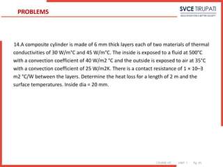
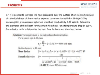
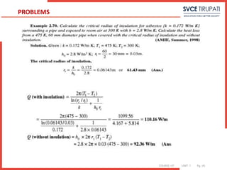
![COURSE: HT UNIT: 1 Pg. (#)
19. Calculate the critical radius of insulation for asbestos [k =0.17 W/m ◦C]
surrounding a pipe and exposed to room air at 20◦C with h=3.0 W/m2 ◦C. Calculate
the heat loss from a 200◦C,5.0-cm-diameter pipe when covered with the critical radius
of insulation and without insulation.
Solution:
ro = k /h =0.17 /3.0 =0.0567 m=5.67 cm
The inside radius of the insulation is 5.0/2=2.5 cm,
so the heat transfer is calculated from Equation as q/L= 2π (200−20) / ln
(5.67/2.5)0.17+ 1
(0.0567)(3.0) =105.7 W/m
Without insulation the convection from the outer surface of the pipe is
q/L=h(2πr)(Ti −To)=(3.0)(2π)(0.025)(200−20)=84.8 W/m
PROBLEMS](https://image.slidesharecdn.com/unitidigitalcontent-240709140328-864ee228/85/UNIT-I-Digital-Content-pptx-engineering-shshhsghsjsjsggh-118-320.jpg)