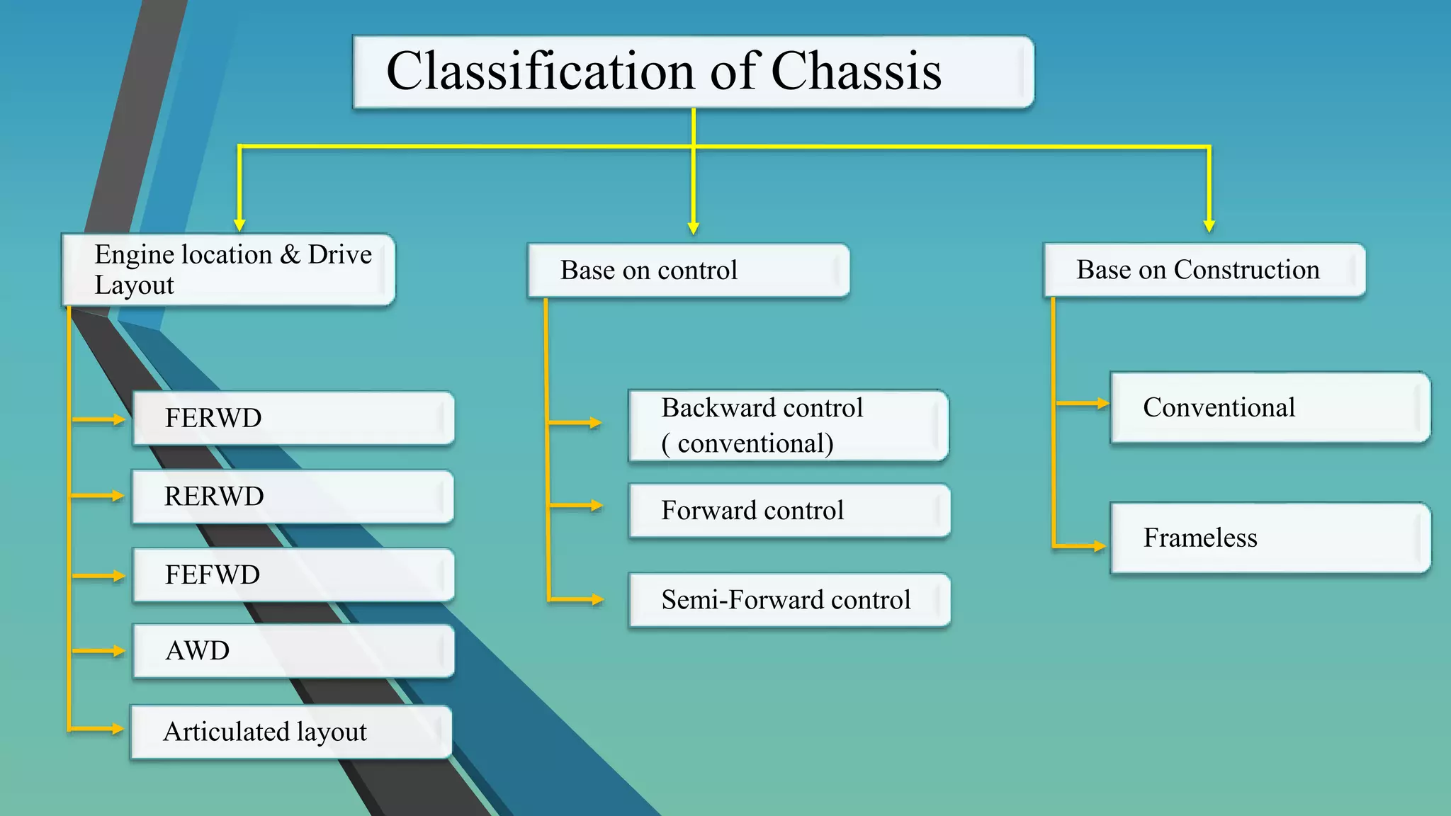
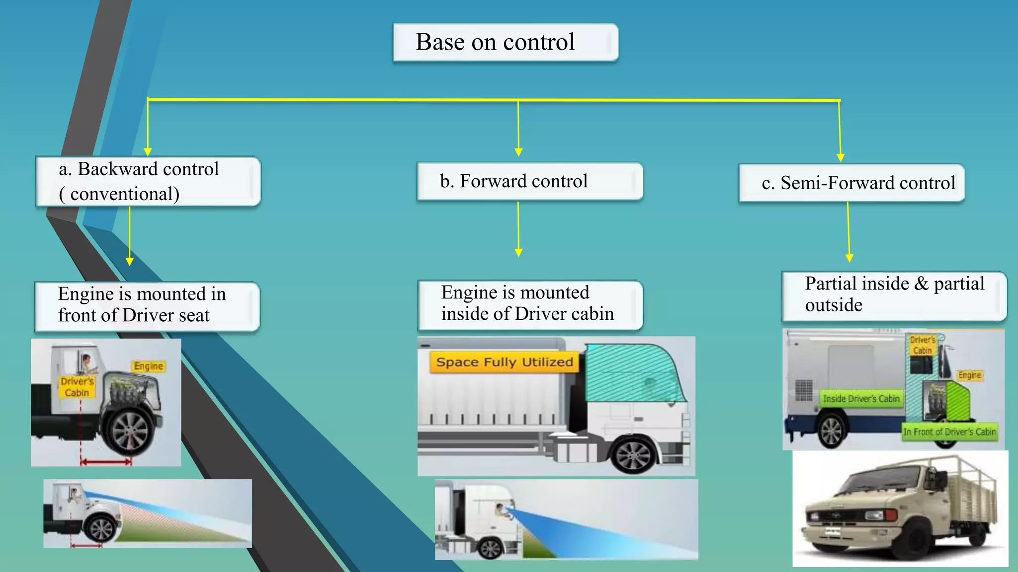
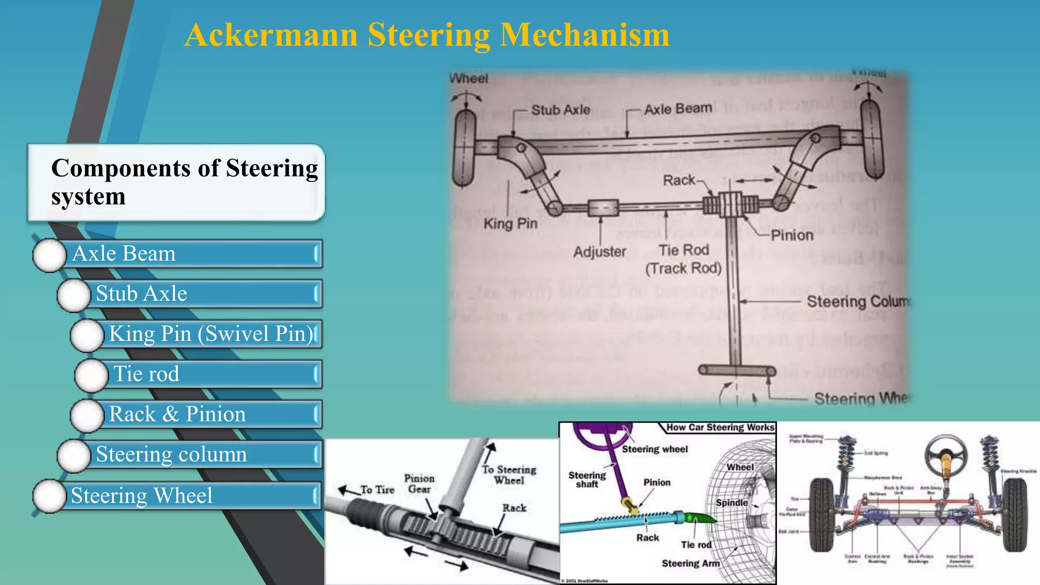
Unit 4: Vehicle Systems
Presented by :-
Pune Vidhyarthi Griha's
College of Engineering and Technology-Pune 09
Prof. Rohan Panage
(7900155751)
Syllabus
 Introduction of chassis layouts, steering system,
suspension system, braking system, cooling system and
fuel injection system and fuel supply system.
 Study of Electric and Hybrid Vehicle systems.
 Study of power transmission system, Clutch, Gear box
(Simple Numerical), propeller shaft, universal joint,
differential gearbox and axles.
 Vehicle active and passive safety arrangements: seat, seat
belts, airbags and antilock brake system.
Chassis Layouts
Def’n : It is a skeleton of the vehicle on which various components
or different system are mounted to Drive the vehicle.
Engine & Cooling system ( Radiator)
Transmission System
Suspension System
Wheels
Steering System
Frame
Axles
Components of Chassis
Classification of Chassis
Engine location & Drive
Layout
Base on control Base on Construction
FERWD Backward control
( conventional)
AWD
FEFWD
RERWD
Articulated layout
Forward control
Semi-Forward control
Conventional
Frameless
A. FERWD :- Front Engine Rear Wheel Drive
The engine is located at the front of the vehicle and
the power is transmitted to rear wheel.
Engine Clutch Gearbox Propeller shaft Differential Wheel
B. RERWD :- Rear Engine Rear Wheel Drive
The engine is located at the rear of the vehicle and
the power is transmitted to rear wheel.
Engine Clutch Gearbox Differential Wheel
Note:- Propeller shaft is missing
C. FEFWD :- Front Engine Front Wheel Drive
The engine is located at the front of the vehicle and
the combine steering and drive at front wheel.
Engine Clutch Gearbox Differential Wheel
Note:- Propeller shaft is missing
D. AWD :- All (4x4) Wheel Drive
The engine is located at the front of the vehicle and
Additional Gearbox is required to split the power and
transfer to rear and front wheel
Engine Clutch Gearbox
Propeller
shaft
Differential Wheel
Transfer
Gearbox
E. Articulated Vehicle Layout
 The engine is located at the front of the vehicle
and the power is transmitted to rear wheel.
 Heavy duty diesel engine, eg. Tractor – Trailer
In India max. length is 15m
Engine Clutch Gearbox Propeller shaft Differential Wheel
Base on control
a. Backward control
( conventional)
b. Forward control c. Semi-Forward control
Engine is mounted in
front of Driver seat
Engine is mounted
inside of Driver cabin
Partial inside & partial
outside
Base on Construction
Conventional
(Frame)
Frameless
a) Includes main frame, sub frame
b) Higher load carrying capacity
c) Easy to assemble
d) Lower dynamic stability at higher
speed
e) Eg. Trucks, buses, etc..,,
a. Single frame ( one part one body)
b. Lower load carrying capacity
c. Difficult to assemble
d. Better dynamic stability at high speed
e. Eg. Bikes, LMV-cars
Steering System
Def”n : System which allow the driver to control the direction of vehicle by turning
the front wheel. This is done by steering wheel.
Principle of steering :
a. For correct steering the axis of rotation of all the wheel should meet at point ‘O’
b. To achieve this inner wheel should be turned greater angle (θ2) than the outer
wheel angle (θ1) ….. (θ2) > (θ1)
Now, AB= a (dist. bet’n front axles)
CD = b (dist. Of wheel track)
AE = L ( Wheel base)
O = Common Centre for all wheels.
Eq’n for correct steering ig given by,
a/L = cot θ1 – cot θ2
Ackermann Steering Mechanism
Axle Beam
Stub Axle
King Pin (Swivel Pin)
Tie rod
Rack & Pinion
Steering column
Steering Wheel
Components of Steering
system
Engine Cooling System
➢ The Engine cooling system is one of the necessary thing that is present in the
Internal Combustion Engine to reduce the temperature of the components
inside the engine. It also helps to reduce the wear out of the component and
provide smooth functioning and long life of the components.
➢ An automobile engine cooling system which uses air or water to remove
waste heat from engine and also keep its temperature safe limit to ensure
efficient , clean operation.
➢ Functions of engine cooling system :
1. It removes heat from the engine.
2. It maintains the engine operating temperature so that engine can run
efficiently
15
Types of cooling System
Air cooling System
Water Cooling System
16
➢ Air Cooling System
➢ It is used in aero planes and motorcycle engines
where the engines are exposed to air directly.
➢ In this system fins or extended surfaces are provided
on the cylinder walls, cylinder head etc,
➢ Heat generated due to combustion in the engine
cylinder will be conducted to the fins and when the
air flows over the fins, heat will be dissipated to air
Examples of Air Cooled Engine:
It is used in scooters, motorcycles
17
➢ The amount of heat dissipated to air depends upon :
(a) Amount of air flowing through the fins.
(b) Fin surface area.
(c) Thermal conductivity of metal used for fins
18
Water Coolin System
Water cooling system mainly consists of :
(a) Radiator,
(b) Thermostat valve,
(c) Water pump,
(d) Fan,
(e) Water Jackets
In this method,
 cooling water jackets are provided around the cylinder, cylinder head, valve seats
etc.
 The water when circulated through the jackets, it absorbs heat of combustion.
 This hot water will then be cooling in the radiator partially by a fan and partially
by the air flow developed by the forward motion of the vehicle.
 The cooled water is again re-circulated through the water jackets
19
FUEL SUPPLY SYSTEMS
➢ The fuel passes through a number of stages before reaching the combustion
chamber.
➢ It includes the filtration and atomization of fuel into fine particles.
➢ It is necessary to atomize the fuel before entering into the combustion
chamber so that complete combustion of fuel can take place.
➢ There are different fuel supply systems for spark ignition (petrol) and
compression ignition (diesel) engine.
20
Fuel Supply System in Petrol Engine
21
MPFI : Multi-point fuel injection system
22
In petrol engine the combustible mixture of fuel is prepared outside the combustion
chamber.
➢ Proper air-fuel ratio is maintained with the help of a device known as carburetor and
this mixture is inducted into the combustion chamber.
➢ The air fuel ratio depends upon the various conditions. The engine needs a richer
mixture while starting and leaner mixture at normal running conditions.
➢ Such conditions must be fulfilled before entering the combustion chamber.
➢ The fuel from the tank is delivered to the float chamber attached to the carburetor
with the help of fuel pump.
➢ The fuel pump maintains the constant pressure. In carburetor fuel is mixed with air
in required proportion.
➢ After that the mixture of fuel and air is inducted into the combustion chamber
23
Fuel Supply System in Diesel Engine
➢ In diesel engine only air is injected during the suction stroke and it
is compressed during compression stroke.
 Fuel is injected into the combustion chamber in the form of fine spray
at the end of compression stroke.
 A fuel injection system in a diesel engine has to satisfy the following
requirements:
1. To inject the fuel at the right time in the cycle.
2. The fuel should be properly atomized.
3. The correct quantity of fuel should be injected depending upon the
load.
24
Fuel pump takes the fuel from fuel tank and delivers it to the fuel filter.
 When the pressure is developed in the injection pump the fuel flows
from injection pump to the fuel injector under pressure.
 The fuel injector is either a single hole nozzle or multi-hole nozzle.
CRDI : Common rail direct
ignition system 25
Gear Box
Def ’n :- It receives the power from
engine through clutch and transmitted to
the wheels.
Function :-
a. Reduce the speed and increases the
torque.
b. Also provide the wide range of gear
ration.
26
Types of Gear Box
A. Selective Gear Box B. Planetary Gear Box
Constant Mesh
Sliding Mesh
Synchromesh
Epicyclic Gear
Automatic
Fluid / torque convertor
Electric type
27
D1 D2 D3
A1
A2
B1
B2
C1
C2
E1
F1 G1
H1
E2 F2 G2
H2
I
Constant Mesh
28
Gear Ratio :-
It is ratio of input speed(Engine) to output
speed ( Propeller Shaft).
i = ni / no
Note :-
a. Gear ratio (i) is maximum in
1st gear & minimum in last gear
Where,
i = Gear ratio/speed ratio
ni = speed of input shaft , rpm
no = speed of output shaft , rmp 29
Power in Gear Box :-
Efficiency of Gear Box = Ratio of Output Power to Input Power
η = Po / Pi
Output Power (Po)
Po = Wo To
60 x 1000
Po = 2 π No To KW
60 x 1000
Input Power (Pi)
Pi = Wi Ti
60 x 1000
Pi = 2 π Ni Ti KW
60 x 1000
30
Q 1. The automobile engine is running at 5800 rpm. The speed of propeller shaft is 1300 rpm in
first gear & 6900 rpm in fifth gear .
Find the gear ratio in in both cases.
Q 2. The Automobile engine is developing 68KW power at 3800 rpm . If the gear ratio in first
gear is 3.9:1,
Determine :
a. Input torque of Gear box
b. output torque of Gear box ( Assume Efficiency is 100%)
c. output seed of Gear box
Q 3. The car engine is developing 79 BH at 5300 rpm . The gear ratio in fifth gear is 0.83 . If
the efficiency f gear box is 90%.
Find :
a) Input torque of Gear box
b) output torque of Gear box
c) output seed of Gear box 31

Unit 4 - Vehicle Classification & Systems.pptx

  • 1.
    Unit 4: VehicleSystems Presented by :- Pune Vidhyarthi Griha's College of Engineering and Technology-Pune 09 Prof. Rohan Panage (7900155751)
  • 2.
    Syllabus  Introduction ofchassis layouts, steering system, suspension system, braking system, cooling system and fuel injection system and fuel supply system.  Study of Electric and Hybrid Vehicle systems.  Study of power transmission system, Clutch, Gear box (Simple Numerical), propeller shaft, universal joint, differential gearbox and axles.  Vehicle active and passive safety arrangements: seat, seat belts, airbags and antilock brake system.
  • 3.
    Chassis Layouts Def’n :It is a skeleton of the vehicle on which various components or different system are mounted to Drive the vehicle. Engine & Cooling system ( Radiator) Transmission System Suspension System Wheels Steering System Frame Axles Components of Chassis
  • 4.
    Classification of Chassis Enginelocation & Drive Layout Base on control Base on Construction FERWD Backward control ( conventional) AWD FEFWD RERWD Articulated layout Forward control Semi-Forward control Conventional Frameless
  • 5.
    A. FERWD :-Front Engine Rear Wheel Drive The engine is located at the front of the vehicle and the power is transmitted to rear wheel. Engine Clutch Gearbox Propeller shaft Differential Wheel
  • 6.
    B. RERWD :-Rear Engine Rear Wheel Drive The engine is located at the rear of the vehicle and the power is transmitted to rear wheel. Engine Clutch Gearbox Differential Wheel Note:- Propeller shaft is missing
  • 7.
    C. FEFWD :-Front Engine Front Wheel Drive The engine is located at the front of the vehicle and the combine steering and drive at front wheel. Engine Clutch Gearbox Differential Wheel Note:- Propeller shaft is missing
  • 8.
    D. AWD :-All (4x4) Wheel Drive The engine is located at the front of the vehicle and Additional Gearbox is required to split the power and transfer to rear and front wheel Engine Clutch Gearbox Propeller shaft Differential Wheel Transfer Gearbox
  • 9.
    E. Articulated VehicleLayout  The engine is located at the front of the vehicle and the power is transmitted to rear wheel.  Heavy duty diesel engine, eg. Tractor – Trailer In India max. length is 15m Engine Clutch Gearbox Propeller shaft Differential Wheel
  • 10.
    Base on control a.Backward control ( conventional) b. Forward control c. Semi-Forward control Engine is mounted in front of Driver seat Engine is mounted inside of Driver cabin Partial inside & partial outside
  • 11.
    Base on Construction Conventional (Frame) Frameless a)Includes main frame, sub frame b) Higher load carrying capacity c) Easy to assemble d) Lower dynamic stability at higher speed e) Eg. Trucks, buses, etc..,, a. Single frame ( one part one body) b. Lower load carrying capacity c. Difficult to assemble d. Better dynamic stability at high speed e. Eg. Bikes, LMV-cars
  • 12.
    Steering System Def”n :System which allow the driver to control the direction of vehicle by turning the front wheel. This is done by steering wheel. Principle of steering : a. For correct steering the axis of rotation of all the wheel should meet at point ‘O’ b. To achieve this inner wheel should be turned greater angle (θ2) than the outer wheel angle (θ1) ….. (θ2) > (θ1) Now, AB= a (dist. bet’n front axles) CD = b (dist. Of wheel track) AE = L ( Wheel base) O = Common Centre for all wheels. Eq’n for correct steering ig given by, a/L = cot θ1 – cot θ2 a/L = cot θ1 – cot θ2
  • 13.
    Ackermann Steering Mechanism AxleBeam Stub Axle King Pin (Swivel Pin) Tie rod Rack & Pinion Steering column Steering Wheel Components of Steering system
  • 15.
    Engine Cooling System ➢The Engine cooling system is one of the necessary thing that is present in the Internal Combustion Engine to reduce the temperature of the components inside the engine. It also helps to reduce the wear out of the component and provide smooth functioning and long life of the components. ➢ An automobile engine cooling system which uses air or water to remove waste heat from engine and also keep its temperature safe limit to ensure efficient , clean operation. ➢ Functions of engine cooling system : 1. It removes heat from the engine. 2. It maintains the engine operating temperature so that engine can run efficiently 15
  • 16.
    Types of coolingSystem Air cooling System Water Cooling System 16
  • 17.
    ➢ Air CoolingSystem ➢ It is used in aero planes and motorcycle engines where the engines are exposed to air directly. ➢ In this system fins or extended surfaces are provided on the cylinder walls, cylinder head etc, ➢ Heat generated due to combustion in the engine cylinder will be conducted to the fins and when the air flows over the fins, heat will be dissipated to air Examples of Air Cooled Engine: It is used in scooters, motorcycles 17
  • 18.
    ➢ The amountof heat dissipated to air depends upon : (a) Amount of air flowing through the fins. (b) Fin surface area. (c) Thermal conductivity of metal used for fins 18
  • 19.
    Water Coolin System Watercooling system mainly consists of : (a) Radiator, (b) Thermostat valve, (c) Water pump, (d) Fan, (e) Water Jackets In this method,  cooling water jackets are provided around the cylinder, cylinder head, valve seats etc.  The water when circulated through the jackets, it absorbs heat of combustion.  This hot water will then be cooling in the radiator partially by a fan and partially by the air flow developed by the forward motion of the vehicle.  The cooled water is again re-circulated through the water jackets 19
  • 20.
    FUEL SUPPLY SYSTEMS ➢The fuel passes through a number of stages before reaching the combustion chamber. ➢ It includes the filtration and atomization of fuel into fine particles. ➢ It is necessary to atomize the fuel before entering into the combustion chamber so that complete combustion of fuel can take place. ➢ There are different fuel supply systems for spark ignition (petrol) and compression ignition (diesel) engine. 20
  • 21.
    Fuel Supply Systemin Petrol Engine 21
  • 22.
    MPFI : Multi-pointfuel injection system 22
  • 23.
    In petrol enginethe combustible mixture of fuel is prepared outside the combustion chamber. ➢ Proper air-fuel ratio is maintained with the help of a device known as carburetor and this mixture is inducted into the combustion chamber. ➢ The air fuel ratio depends upon the various conditions. The engine needs a richer mixture while starting and leaner mixture at normal running conditions. ➢ Such conditions must be fulfilled before entering the combustion chamber. ➢ The fuel from the tank is delivered to the float chamber attached to the carburetor with the help of fuel pump. ➢ The fuel pump maintains the constant pressure. In carburetor fuel is mixed with air in required proportion. ➢ After that the mixture of fuel and air is inducted into the combustion chamber 23
  • 24.
    Fuel Supply Systemin Diesel Engine ➢ In diesel engine only air is injected during the suction stroke and it is compressed during compression stroke.  Fuel is injected into the combustion chamber in the form of fine spray at the end of compression stroke.  A fuel injection system in a diesel engine has to satisfy the following requirements: 1. To inject the fuel at the right time in the cycle. 2. The fuel should be properly atomized. 3. The correct quantity of fuel should be injected depending upon the load. 24
  • 25.
    Fuel pump takesthe fuel from fuel tank and delivers it to the fuel filter.  When the pressure is developed in the injection pump the fuel flows from injection pump to the fuel injector under pressure.  The fuel injector is either a single hole nozzle or multi-hole nozzle. CRDI : Common rail direct ignition system 25
  • 26.
    Gear Box Def ’n:- It receives the power from engine through clutch and transmitted to the wheels. Function :- a. Reduce the speed and increases the torque. b. Also provide the wide range of gear ration. 26
  • 27.
    Types of GearBox A. Selective Gear Box B. Planetary Gear Box Constant Mesh Sliding Mesh Synchromesh Epicyclic Gear Automatic Fluid / torque convertor Electric type 27
  • 28.
    D1 D2 D3 A1 A2 B1 B2 C1 C2 E1 F1G1 H1 E2 F2 G2 H2 I Constant Mesh 28
  • 29.
    Gear Ratio :- Itis ratio of input speed(Engine) to output speed ( Propeller Shaft). i = ni / no Note :- a. Gear ratio (i) is maximum in 1st gear & minimum in last gear Where, i = Gear ratio/speed ratio ni = speed of input shaft , rpm no = speed of output shaft , rmp 29
  • 30.
    Power in GearBox :- Efficiency of Gear Box = Ratio of Output Power to Input Power η = Po / Pi Output Power (Po) Po = Wo To 60 x 1000 Po = 2 π No To KW 60 x 1000 Input Power (Pi) Pi = Wi Ti 60 x 1000 Pi = 2 π Ni Ti KW 60 x 1000 30
  • 31.
    Q 1. Theautomobile engine is running at 5800 rpm. The speed of propeller shaft is 1300 rpm in first gear & 6900 rpm in fifth gear . Find the gear ratio in in both cases. Q 2. The Automobile engine is developing 68KW power at 3800 rpm . If the gear ratio in first gear is 3.9:1, Determine : a. Input torque of Gear box b. output torque of Gear box ( Assume Efficiency is 100%) c. output seed of Gear box Q 3. The car engine is developing 79 BH at 5300 rpm . The gear ratio in fifth gear is 0.83 . If the efficiency f gear box is 90%. Find : a) Input torque of Gear box b) output torque of Gear box c) output seed of Gear box 31