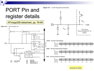
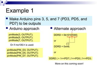
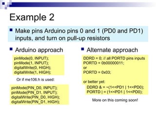
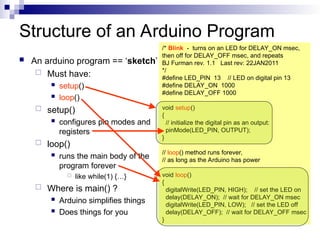
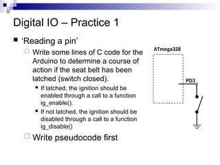
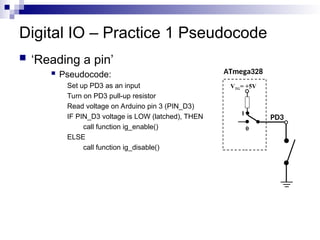
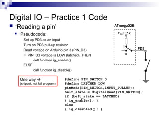
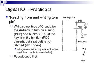
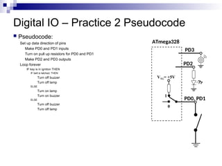
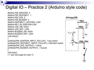
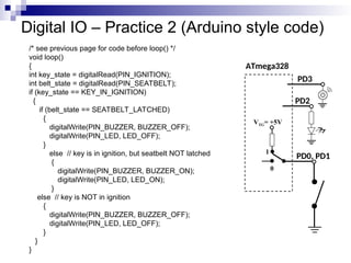
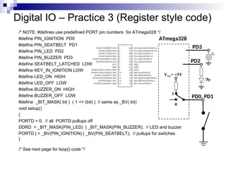
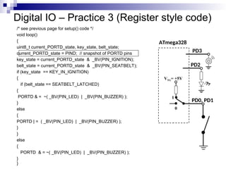
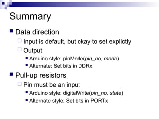
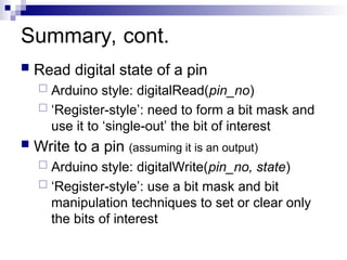
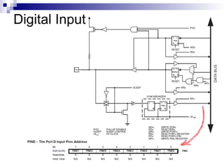
Unit 4: Introduction to
Microcontrollers_Part1
Learning Objectives
 Explain the general architecture of a
microcontroller
 List the key features of the ATmega328
microcontroller
 Explain the features and elements of the Arduino
 Explain the concepts of microcontroller pins as
inputs and outputs
 Convert between binary and hexadecimal digits
Mechatronics Concept Map
Controller
(Hardware & Software)
System to
Control
Sensor
Signal
Conditioning
Power
Interface
Actuator
User
Interface
Power
Source
BJ Furman 22JAN11
ME 106
ME 154
ME 157
ME 195
ME 120
ME 297A
ME 106
ME 120
ME 106
ME 190
ME 187
ME 110
ME 136
ME 154
ME 157
ME 182
ME 189
ME 195
ME 106
ME 120
ME 106
INTEGRATION
What is a Microcontroller?
http://www.freescale.com/files/microcontrollers/doc/ref_manual/M68HC05TB.pdf
ANALOG
INPUTS
What is the difference between a ‘Digital Input’ and an ‘Analog Input’?
ATmega328 Internal Architecture
ATmega328 data sheet pp. 2, 5
http://www.adafruit.com/index.php?
ATmega328 Features
ATmega328 data sheet p. 1
http://www.atmel.com/Images/Atmel-8271-8-bit-AVR-Microcontroller
-ATmega48A-48PA-88A-88PA-168A-168PA-328-328P_datasheet.p
df
Arduino Duemilanove
http://www.arduino.cc/en/Main/ArduinoBoardDuemilanove
http://arduino.cc/en/uploads/Main/ArduinoDuemilanove.jpg
Pin 13 LED
USB
connector
Barrel jack
Digital pins header
Reset button
ATmega328 MCU
Analog pins header
Power-ground header
See the handout:
Arduino_ATmega328_pin_mapping_and_schematic
Arduino Uno R3
http://www.adafruit.com/index.php?
main_page=popup_image&pID=50
ATmega16u2 replaces FT232RL for USB-serial communication
See: http://learn.adafruit.com/arduino-tips-tricks-and-techniques/arduino-uno-faq
Arduino Due
Atmel SAM3X8E processor (32 bit ARM Cortex M3 architecture, 84MHz)
http://www.adafruit.com/index.php?main_page=popup_image&pID=1076
See: http://arduino.cc/en/Main/ArduinoBoardDue
Note: 3.3 V !!
Arduino Duemilanove/Uno Features
Microcontroller ATmega168/328
Operating Voltage 5V
Input Voltage (recommended) 7-12V
Input Voltage (limits) 6-20V
Digital I/O Pins 14 (of which 6 provide PWM output)
Analog Input Pins 6
DC Current per I/O Pin 40 mA
DC Current for 3.3V Pin 50 mA
Flash Memory
16 KB (ATmega168) or 32 KB (ATmega328) of which 2
KB used by bootloader
SRAM 1 KB (ATmega168) or 2 KB (ATmega328)
EEPROM 512 bytes (ATmega168) or 1 KB (ATmega328)
Clock Speed 16 MHz
http://www.arduino.cc/en/Main/ArduinoBoardDuemilanove
http://arduino.cc/en/uploads/Main/arduino-duemilanove-schematic.pdf
ATmega328 Microcontroller
Pin number
Pin name
Special
function
Source:http://www.atmel.com/dyn/products/product_card.asp?PN=ATmega328P
Note the
limitations!
p. 316
Absolute Maximums
ATmega328 data sheet p. 316
Microcontroller Ports and Pins
 The communication channels
through which information
flows into or out of the
microcontroller
 Ex. PORTB
 Pins PB0 – PB7
 May not be contiguous
 Often bi-directional
C
See next slides!
Port Pin Data Directionality
 Input
 When you want to take information from the external
world (sensors) into the MCU
 Output
 When you want to change the state of something
outside the MCU (turn a motor on or off, etc.)
 Pins default to input direction on power-up or
reset
 Your program can set or change the
directionality of a pin at any time
ATmega328
Block Diagram
Input
Output
M68HC11 microcontroller
Setting the Pin Data Direction
 Arduino
 pinMode(pin_no., dir)
 Ex. Make Arduino pin 3 (PD3) an output
 pinMode(3, OUTPUT);
 pinMode(PIN_D3, OUTPUT); // with me106.h
 Note: one pin at a time
 Suppose you wanted Arduino pins 3, 5, and 7 (PD3,
PD5, and PD7) to be outputs?
 Is there a way to make them all outputs at the same
time?
 Yes! Answer coming later…
Pin Voltages
 Microcontrollers are fundamentally digital
devices. For digital IO pins:
 Information is ‘coded’ in two discrete states:
 HIGH or LOW (logic: 1 or 0)
 Voltages
 TTL
 5 V (for HIGH)
 0 V (for LOW)
 3.3 V CMOS
 3.3 V (for HIGH)
 0 V (for LOW)
Pin Used as an Output
 Turn on an LED, which is
connected to pin Arduino pin 0
(PD0) (note the resistor!)
 What should the data
direction be for pin 0 (PD0)?
 pinMode(____, ____);
 Turn on the LED
 digitalWrite(PIN_LED,HIGH);
 Turn off the LED
 digitalWrite(PIN_LED,LOW);
ATmega328
Arduino
pin 0
(PD0)
Pins as Inputs and Pull-up Resistors - 1
 Using a switch as a sensor
 Ex. Seat belt sensor
 Detect the switch state
 What should the data direction be
for Arduino pin 3 (PD3)?
 pinMode(____, ____);
 What will the voltage be on PD3
when the switch is closed?
 What will the voltage be on PD3
when the switch is open?
 Indeterminate!
ATmega328
Arduino
pin 3
(PD3)
SPST
momentary
Pins as Inputs and Pull-up Resistors - 2
 Switch as a sensor, cont.
 Make the voltage on the pin
determinate by turning on the pull-
up resistor for PD3
 Assuming PD3 is an input:
 digitalWrite(PIN_SWITCH,HIGH);
turns on the “pull-up” resistor
 pinMode(PIN_SWITCH,INPUT_PULLUP);
 What will the voltage on PD3 be when
the switch is open?
 VTG
 What will the voltage on PD3 be when
the switch is closed?
ATmega328
PD3
1
VTG= +5V
0
Pins as Inputs and Pull-up Resistors - 3
 Switch as a sensor, cont.
 To turn off the pull-up
resistor
 Assuming PD3 is an input:
digitalWrite(PIN_SWITCH,LOW);
turns the “pull-up” resistor off
ATmega328
PD3
VTG= +5V
0
1
Pins as Inputs and Pull-up Resistors - 4
 Possibility of ‘weak drive’
when pull-up resistor is
turned on
 Pin set as an input with a
pull-up resistor turned on
can source a small current
 Remember this!
ATmega328
PD3
VTG= +5V
0
1
iweak
Handling the Arduino - How NOT to Do It!
Improper Handling - NEVER!!!
Handling the Arduino - The Proper Way
Proper Handling - by the edges!!!
So What?
 Recall the question:
 Is there a way change the data direction for a set of
pins all at the same time?
 All the work of MCU happens through registers
(special memory locations)
 Registers on the Atmega328 are 8-bits wide
 The data direction register (DDRx) handles the
data directions for pins in PORTx
Source:http://www.atmel.com/dyn/products/product_card.asp?PN=ATmega328P p. 93
Data Direction Register
 If the bit is zero -> pin will be an input
 Making a bit to be zero == ‘clearing the bit’
 If the bit is one -> pin will be an output
 Making a bit to be one == ‘setting the bit’
 To change the data direction for a set of pins
belonging to PORTx at the same time:
1. Determine which bits need to be set and cleared in
DDRx
2. Store the binary number or its equivalent (in an
alternate base, such as hex) into DDRx
ATmega328 Registers of Interest
 See the ATmega328 data sheet, pp. 76-94
 For digital IO, the important registers are:
 DDRx
 Data Direction bit in DDRx register (read/write)
 PORTx
 PORTx data register (read/write)
 PINx
 PINx register (read only)
PORT Pin and
register details
ATmega328 datasheet, pp. 76-94
Jump to bits
Example 1
 Arduino approach  Alternate approach
 Make Arduino pins 3, 5, and 7 (PD3, PD5, and
PD7) to be outputs
pinMode(3, OUTPUT);
pinMode(5, OUTPUT);
pinMode(7, OUTPUT);
DDRD = 0b10101000;
or
DDRD = 0xA8;
or
DDRD | = 1<<PD7 | 1<<PD5 | 1<<PD3;
More on this coming soon!
Or if me106.h is used:
pinMode(PIN_D3, OUTPUT);
pinMode(PIN_D5, OUTPUT);
pinMode(PIN_D7, OUTPUT);
Example 2
 Arduino approach  Alternate approach
 Make pins Arduino pins 0 and 1 (PD0 and PD1)
inputs, and turn on pull-up resistors
pinMode(0, INPUT);
pinMode(1, INPUT);
digitalWrite(0, HIGH);
digitalWrite(1, HIGH);
DDRD = 0; // all PORTD pins inputs
PORTD = 0b00000011;
or
PORTD = 0x03;
or better yet:
DDRD & = ~(1<<PD1 | 1<<PD0);
PORTD | = (1<<PD1 | 1<<PD0);
More on this coming soon!
Or if me106.h is used:
pinMode(PIN_D0, INPUT);
pinMode(PIN_D1, INPUT);
digitalWrite(PIN_D0, HIGH);
digitalWrite(PIN_D1, HIGH);
Structure of an Arduino Program
 An arduino program == ‘sketch’
 Must have:
 setup()
 loop()
 setup()
 configures pin modes and
registers
 loop()
 runs the main body of the
program forever
 like while(1) {…}
 Where is main() ?
 Arduino simplifies things
 Does things for you
/* Blink - turns on an LED for DELAY_ON msec,
then off for DELAY_OFF msec, and repeats
BJ Furman rev. 1.1 Last rev: 22JAN2011
*/
#define LED_PIN 13 // LED on digital pin 13
#define DELAY_ON 1000
#define DELAY_OFF 1000
void setup()
{
// initialize the digital pin as an output:
pinMode(LED_PIN, OUTPUT);
}
// loop() method runs forever,
// as long as the Arduino has power
void loop()
{
digitalWrite(LED_PIN, HIGH); // set the LED on
delay(DELAY_ON); // wait for DELAY_ON msec
digitalWrite(LED_PIN, LOW); // set the LED off
delay(DELAY_OFF); // wait for DELAY_OFF msec
}
Digital IO – Practice 1
 ‘Reading a pin’
 Write some lines of C code for the
Arduino to determine a course of
action if the seat belt has been
latched (switch closed).
 If latched, the ignition should be
enabled through a call to a function
ig_enable().
 If not latched, the ignition should be
disabled through a call to a function
ig_disable()
 Write pseudocode first
ATmega328
PD3
Digital IO – Practice 1 Pseudocode
 ‘Reading a pin’
 Pseudocode:
Set up PD3 as an input
Turn on PD3 pull-up resistor
Read voltage on Arduino pin 3 (PIN_D3)
IF PIN_D3 voltage is LOW (latched), THEN
call function ig_enable()
ELSE
call function ig_disable()
ATmega328
PD3
VTG= +5V
0
1
Digital IO – Practice 1 Code
 ‘Reading a pin’
 Pseudocode:
Set up PD3 as an input
Turn on PD3 pull-up resistor
Read voltage on Arduino pin 3 (PIN_D3)
IF PIN_D3 voltage is LOW (latched), THEN
call function ig_enable()
ELSE
call function ig_disable()
ATmega328
PD3
VTG= +5V
0
1
#define PIN_SWITCH 3
#define LATCHED LOW
pinMode(PIN_SWITCH,INPUT_PULLUP);
belt_state = digitalRead(PIN_SWITCH);
if (belt_state == LATCHED)
{ ig_enable(); }
else
{ ig_disabled(); }
One way 
(snippet, not full program)
Digital IO – Practice 2
 ‘Reading from and writing to a
pin’
 Write some lines of C code for
the Arduino to turn on a lamp
(PD2) and buzzer (PD3) if the
key is in the ignition (PD0
closed), but seat belt is not
latched (PD1 open)
 (diagram shows only one of the two
switches, but both are similar)
 Pseudocode first
ATmega328
PD0, PD1
PD2
PD3
Digital IO – Practice 2 Pseudocode
 Pseudocode:
Set up data direction of pins
Make PD0 and PD1 inputs
Turn on pull up resistors for PD0 and PD1
Make PD2 and PD3 outputs
Loop forever
IF key is in ignition THEN
IF belt is latched, THEN
Turn off buzzer
Turn off lamp
ELSE
Turn on lamp
Turn on buzzer
ELSE
Turn off buzzer
Turn off lamp
ATmega328
PD0, PD1
VTG= +5V
0
1
PD2
PD3
Digital IO – Practice 2 (Arduino style code)
#define PIN_IGNITION 0
#define PIN_SEATBELT 1
#define PIN_LED 2
#define PIN_BUZZER 3
#define SEATBELT_LATCHED LOW
#define KEY_IN_IGNITION LOW
#define LED_ON HIGH
#define LED_OFF LOW
#define BUZZER_ON HIGH
#define BUZZER_OFF LOW
void setup()
{
pinMode(PIN_IGNITION, INPUT_PULLUP); // key switch
pinMode(PIN_SEATBELT, INPUT_PULLUP); // belt latch switch
pinMode(PIN_LED, OUTPUT); // lamp
pinMode(PIN_BUZZER, OUTPUT); // buzzer
}
void loop()
{ /* see next page for code */}
ATmega328
PD0, PD1
VTG= +5V
0
1
PD2
PD3
Digital IO – Practice 2 (Arduino style code)
/* see previous page for code before loop() */
void loop()
{
int key_state = digitalRead(PIN_IGNITION);
int belt_state = digitalRead(PIN_SEATBELT);
if (key_state == KEY_IN_IGNITION)
{
if (belt_state == SEATBELT_LATCHED)
{
digitalWrite(PIN_BUZZER, BUZZER_OFF);
digitalWrite(PIN_LED, LED_OFF);
}
else // key is in ignition, but seatbelt NOT latched
{
digitalWrite(PIN_BUZZER, BUZZER_ON);
digitalWrite(PIN_LED, LED_ON);
}
else // key is NOT in ignition
{
digitalWrite(PIN_BUZZER, BUZZER_OFF);
digitalWrite(PIN_LED, LED_OFF);
}
}
}
ATmega328
PD0, PD1
VTG= +5V
0
1
PD2
PD3
Digital IO – Practice 3 (Register style code)
/* NOTE: #defines use predefined PORT pin numbers for ATmega328 */
#define PIN_IGNITION PD0
#define PIN_SEATBELT PD1
#define PIN_LED PD2
#define PIN_BUZZER PD3
#define SEATBELT_LATCHED LOW
#define KEY_IN_IGNITION LOW
#define LED_ON HIGH
#define LED_OFF LOW
#define BUZZER_ON HIGH
#define BUZZER_OFF LOW
#define _BIT_MASK( bit ) ( 1 << (bit) ) // same as _BV( bit)
void setup()
{
PORTD = 0; // all PORTD pullups off
DDRD = _BIT_MASK(PIN_LED) | _BIT_MASK(PIN_BUZZER); // LED and buzzer
PORTD | = _BV(PIN_IGNITION) | _BV(PIN_SEATBELT); // pullups for switches
}
/* See next page for loop() code */
ATmega328
PD0, PD1
VTG= +5V
0
1
PD2
PD3
Digital IO – Practice 3 (Register style code)
/* see previous page for setup() code */
void loop()
{
uint8_t current_PORTD_state, key_state, belt_state;
current_PORTD_state = PIND; // snapshot of PORTD pins
key_state = current_PORTD_state & _BV(PIN_IGNITION);
belt_state = current_PORTD_state & _BV(PIN_SEATBELT);
if (key_state == KEY_IN_IGNITION)
{
if (belt_state == SEATBELT_LATCHED)
{
PORTD & = ~( _BV(PIN_LED) | _BV(PIN_BUZZER) );
}
else
{
PORTD | = ( _BV(PIN_LED) | _BV(PIN_BUZZER) );
}
}
else
{
PORTD & = ~( _BV(PIN_LED) | _BV(PIN_BUZZER) );
}
}
ATmega328
PD0, PD1
VTG= +5V
0
1
PD2
PD3
Summary
 Data direction
 Input is default, but okay to set explictly
 Output
 Arduino style: pinMode(pin_no, mode)
 Alternate: Set bits in DDRx
 Pull-up resistors
 Pin must be an input
 Arduino style: digitalWrite(pin_no, state)
 Alternate style: Set bits in PORTx
Summary, cont.
 Read digital state of a pin
 Arduino style: digitalRead(pin_no)
 ‘Register-style’: need to form a bit mask and
use it to ‘single-out’ the bit of interest
 Write to a pin (assuming it is an output)
 Arduino style: digitalWrite(pin_no, state)
 ‘Register-style’: use a bit mask and bit
manipulation techniques to set or clear only
the bits of interest
Digital Input

Unit 4 Part I.ppt this contains notes for

  • 1.
    Unit 4: Introductionto Microcontrollers_Part1
  • 2.
    Learning Objectives  Explainthe general architecture of a microcontroller  List the key features of the ATmega328 microcontroller  Explain the features and elements of the Arduino  Explain the concepts of microcontroller pins as inputs and outputs  Convert between binary and hexadecimal digits
  • 3.
    Mechatronics Concept Map Controller (Hardware& Software) System to Control Sensor Signal Conditioning Power Interface Actuator User Interface Power Source BJ Furman 22JAN11 ME 106 ME 154 ME 157 ME 195 ME 120 ME 297A ME 106 ME 120 ME 106 ME 190 ME 187 ME 110 ME 136 ME 154 ME 157 ME 182 ME 189 ME 195 ME 106 ME 120 ME 106 INTEGRATION
  • 4.
    What is aMicrocontroller? http://www.freescale.com/files/microcontrollers/doc/ref_manual/M68HC05TB.pdf ANALOG INPUTS What is the difference between a ‘Digital Input’ and an ‘Analog Input’?
  • 5.
    ATmega328 Internal Architecture ATmega328data sheet pp. 2, 5 http://www.adafruit.com/index.php?
  • 6.
    ATmega328 Features ATmega328 datasheet p. 1 http://www.atmel.com/Images/Atmel-8271-8-bit-AVR-Microcontroller -ATmega48A-48PA-88A-88PA-168A-168PA-328-328P_datasheet.p df
  • 7.
    Arduino Duemilanove http://www.arduino.cc/en/Main/ArduinoBoardDuemilanove http://arduino.cc/en/uploads/Main/ArduinoDuemilanove.jpg Pin 13LED USB connector Barrel jack Digital pins header Reset button ATmega328 MCU Analog pins header Power-ground header See the handout: Arduino_ATmega328_pin_mapping_and_schematic
  • 8.
    Arduino Uno R3 http://www.adafruit.com/index.php? main_page=popup_image&pID=50 ATmega16u2replaces FT232RL for USB-serial communication See: http://learn.adafruit.com/arduino-tips-tricks-and-techniques/arduino-uno-faq
  • 9.
    Arduino Due Atmel SAM3X8Eprocessor (32 bit ARM Cortex M3 architecture, 84MHz) http://www.adafruit.com/index.php?main_page=popup_image&pID=1076 See: http://arduino.cc/en/Main/ArduinoBoardDue Note: 3.3 V !!
  • 10.
    Arduino Duemilanove/Uno Features MicrocontrollerATmega168/328 Operating Voltage 5V Input Voltage (recommended) 7-12V Input Voltage (limits) 6-20V Digital I/O Pins 14 (of which 6 provide PWM output) Analog Input Pins 6 DC Current per I/O Pin 40 mA DC Current for 3.3V Pin 50 mA Flash Memory 16 KB (ATmega168) or 32 KB (ATmega328) of which 2 KB used by bootloader SRAM 1 KB (ATmega168) or 2 KB (ATmega328) EEPROM 512 bytes (ATmega168) or 1 KB (ATmega328) Clock Speed 16 MHz http://www.arduino.cc/en/Main/ArduinoBoardDuemilanove
  • 11.
  • 12.
    ATmega328 Microcontroller Pin number Pinname Special function Source:http://www.atmel.com/dyn/products/product_card.asp?PN=ATmega328P Note the limitations! p. 316
  • 13.
  • 14.
    Microcontroller Ports andPins  The communication channels through which information flows into or out of the microcontroller  Ex. PORTB  Pins PB0 – PB7  May not be contiguous  Often bi-directional C See next slides!
  • 15.
    Port Pin DataDirectionality  Input  When you want to take information from the external world (sensors) into the MCU  Output  When you want to change the state of something outside the MCU (turn a motor on or off, etc.)  Pins default to input direction on power-up or reset  Your program can set or change the directionality of a pin at any time
  • 16.
  • 17.
  • 18.
    Setting the PinData Direction  Arduino  pinMode(pin_no., dir)  Ex. Make Arduino pin 3 (PD3) an output  pinMode(3, OUTPUT);  pinMode(PIN_D3, OUTPUT); // with me106.h  Note: one pin at a time  Suppose you wanted Arduino pins 3, 5, and 7 (PD3, PD5, and PD7) to be outputs?  Is there a way to make them all outputs at the same time?  Yes! Answer coming later…
  • 19.
    Pin Voltages  Microcontrollersare fundamentally digital devices. For digital IO pins:  Information is ‘coded’ in two discrete states:  HIGH or LOW (logic: 1 or 0)  Voltages  TTL  5 V (for HIGH)  0 V (for LOW)  3.3 V CMOS  3.3 V (for HIGH)  0 V (for LOW)
  • 20.
    Pin Used asan Output  Turn on an LED, which is connected to pin Arduino pin 0 (PD0) (note the resistor!)  What should the data direction be for pin 0 (PD0)?  pinMode(____, ____);  Turn on the LED  digitalWrite(PIN_LED,HIGH);  Turn off the LED  digitalWrite(PIN_LED,LOW); ATmega328 Arduino pin 0 (PD0)
  • 21.
    Pins as Inputsand Pull-up Resistors - 1  Using a switch as a sensor  Ex. Seat belt sensor  Detect the switch state  What should the data direction be for Arduino pin 3 (PD3)?  pinMode(____, ____);  What will the voltage be on PD3 when the switch is closed?  What will the voltage be on PD3 when the switch is open?  Indeterminate! ATmega328 Arduino pin 3 (PD3) SPST momentary
  • 22.
    Pins as Inputsand Pull-up Resistors - 2  Switch as a sensor, cont.  Make the voltage on the pin determinate by turning on the pull- up resistor for PD3  Assuming PD3 is an input:  digitalWrite(PIN_SWITCH,HIGH); turns on the “pull-up” resistor  pinMode(PIN_SWITCH,INPUT_PULLUP);  What will the voltage on PD3 be when the switch is open?  VTG  What will the voltage on PD3 be when the switch is closed? ATmega328 PD3 1 VTG= +5V 0
  • 23.
    Pins as Inputsand Pull-up Resistors - 3  Switch as a sensor, cont.  To turn off the pull-up resistor  Assuming PD3 is an input: digitalWrite(PIN_SWITCH,LOW); turns the “pull-up” resistor off ATmega328 PD3 VTG= +5V 0 1
  • 24.
    Pins as Inputsand Pull-up Resistors - 4  Possibility of ‘weak drive’ when pull-up resistor is turned on  Pin set as an input with a pull-up resistor turned on can source a small current  Remember this! ATmega328 PD3 VTG= +5V 0 1 iweak
  • 25.
    Handling the Arduino- How NOT to Do It! Improper Handling - NEVER!!!
  • 26.
    Handling the Arduino- The Proper Way Proper Handling - by the edges!!!
  • 27.
    So What?  Recallthe question:  Is there a way change the data direction for a set of pins all at the same time?  All the work of MCU happens through registers (special memory locations)  Registers on the Atmega328 are 8-bits wide  The data direction register (DDRx) handles the data directions for pins in PORTx Source:http://www.atmel.com/dyn/products/product_card.asp?PN=ATmega328P p. 93
  • 28.
    Data Direction Register If the bit is zero -> pin will be an input  Making a bit to be zero == ‘clearing the bit’  If the bit is one -> pin will be an output  Making a bit to be one == ‘setting the bit’  To change the data direction for a set of pins belonging to PORTx at the same time: 1. Determine which bits need to be set and cleared in DDRx 2. Store the binary number or its equivalent (in an alternate base, such as hex) into DDRx
  • 29.
    ATmega328 Registers ofInterest  See the ATmega328 data sheet, pp. 76-94  For digital IO, the important registers are:  DDRx  Data Direction bit in DDRx register (read/write)  PORTx  PORTx data register (read/write)  PINx  PINx register (read only)
  • 30.
    PORT Pin and registerdetails ATmega328 datasheet, pp. 76-94 Jump to bits
  • 31.
    Example 1  Arduinoapproach  Alternate approach  Make Arduino pins 3, 5, and 7 (PD3, PD5, and PD7) to be outputs pinMode(3, OUTPUT); pinMode(5, OUTPUT); pinMode(7, OUTPUT); DDRD = 0b10101000; or DDRD = 0xA8; or DDRD | = 1<<PD7 | 1<<PD5 | 1<<PD3; More on this coming soon! Or if me106.h is used: pinMode(PIN_D3, OUTPUT); pinMode(PIN_D5, OUTPUT); pinMode(PIN_D7, OUTPUT);
  • 32.
    Example 2  Arduinoapproach  Alternate approach  Make pins Arduino pins 0 and 1 (PD0 and PD1) inputs, and turn on pull-up resistors pinMode(0, INPUT); pinMode(1, INPUT); digitalWrite(0, HIGH); digitalWrite(1, HIGH); DDRD = 0; // all PORTD pins inputs PORTD = 0b00000011; or PORTD = 0x03; or better yet: DDRD & = ~(1<<PD1 | 1<<PD0); PORTD | = (1<<PD1 | 1<<PD0); More on this coming soon! Or if me106.h is used: pinMode(PIN_D0, INPUT); pinMode(PIN_D1, INPUT); digitalWrite(PIN_D0, HIGH); digitalWrite(PIN_D1, HIGH);
  • 33.
    Structure of anArduino Program  An arduino program == ‘sketch’  Must have:  setup()  loop()  setup()  configures pin modes and registers  loop()  runs the main body of the program forever  like while(1) {…}  Where is main() ?  Arduino simplifies things  Does things for you /* Blink - turns on an LED for DELAY_ON msec, then off for DELAY_OFF msec, and repeats BJ Furman rev. 1.1 Last rev: 22JAN2011 */ #define LED_PIN 13 // LED on digital pin 13 #define DELAY_ON 1000 #define DELAY_OFF 1000 void setup() { // initialize the digital pin as an output: pinMode(LED_PIN, OUTPUT); } // loop() method runs forever, // as long as the Arduino has power void loop() { digitalWrite(LED_PIN, HIGH); // set the LED on delay(DELAY_ON); // wait for DELAY_ON msec digitalWrite(LED_PIN, LOW); // set the LED off delay(DELAY_OFF); // wait for DELAY_OFF msec }
  • 34.
    Digital IO –Practice 1  ‘Reading a pin’  Write some lines of C code for the Arduino to determine a course of action if the seat belt has been latched (switch closed).  If latched, the ignition should be enabled through a call to a function ig_enable().  If not latched, the ignition should be disabled through a call to a function ig_disable()  Write pseudocode first ATmega328 PD3
  • 35.
    Digital IO –Practice 1 Pseudocode  ‘Reading a pin’  Pseudocode: Set up PD3 as an input Turn on PD3 pull-up resistor Read voltage on Arduino pin 3 (PIN_D3) IF PIN_D3 voltage is LOW (latched), THEN call function ig_enable() ELSE call function ig_disable() ATmega328 PD3 VTG= +5V 0 1
  • 36.
    Digital IO –Practice 1 Code  ‘Reading a pin’  Pseudocode: Set up PD3 as an input Turn on PD3 pull-up resistor Read voltage on Arduino pin 3 (PIN_D3) IF PIN_D3 voltage is LOW (latched), THEN call function ig_enable() ELSE call function ig_disable() ATmega328 PD3 VTG= +5V 0 1 #define PIN_SWITCH 3 #define LATCHED LOW pinMode(PIN_SWITCH,INPUT_PULLUP); belt_state = digitalRead(PIN_SWITCH); if (belt_state == LATCHED) { ig_enable(); } else { ig_disabled(); } One way  (snippet, not full program)
  • 37.
    Digital IO –Practice 2  ‘Reading from and writing to a pin’  Write some lines of C code for the Arduino to turn on a lamp (PD2) and buzzer (PD3) if the key is in the ignition (PD0 closed), but seat belt is not latched (PD1 open)  (diagram shows only one of the two switches, but both are similar)  Pseudocode first ATmega328 PD0, PD1 PD2 PD3
  • 38.
    Digital IO –Practice 2 Pseudocode  Pseudocode: Set up data direction of pins Make PD0 and PD1 inputs Turn on pull up resistors for PD0 and PD1 Make PD2 and PD3 outputs Loop forever IF key is in ignition THEN IF belt is latched, THEN Turn off buzzer Turn off lamp ELSE Turn on lamp Turn on buzzer ELSE Turn off buzzer Turn off lamp ATmega328 PD0, PD1 VTG= +5V 0 1 PD2 PD3
  • 39.
    Digital IO –Practice 2 (Arduino style code) #define PIN_IGNITION 0 #define PIN_SEATBELT 1 #define PIN_LED 2 #define PIN_BUZZER 3 #define SEATBELT_LATCHED LOW #define KEY_IN_IGNITION LOW #define LED_ON HIGH #define LED_OFF LOW #define BUZZER_ON HIGH #define BUZZER_OFF LOW void setup() { pinMode(PIN_IGNITION, INPUT_PULLUP); // key switch pinMode(PIN_SEATBELT, INPUT_PULLUP); // belt latch switch pinMode(PIN_LED, OUTPUT); // lamp pinMode(PIN_BUZZER, OUTPUT); // buzzer } void loop() { /* see next page for code */} ATmega328 PD0, PD1 VTG= +5V 0 1 PD2 PD3
  • 40.
    Digital IO –Practice 2 (Arduino style code) /* see previous page for code before loop() */ void loop() { int key_state = digitalRead(PIN_IGNITION); int belt_state = digitalRead(PIN_SEATBELT); if (key_state == KEY_IN_IGNITION) { if (belt_state == SEATBELT_LATCHED) { digitalWrite(PIN_BUZZER, BUZZER_OFF); digitalWrite(PIN_LED, LED_OFF); } else // key is in ignition, but seatbelt NOT latched { digitalWrite(PIN_BUZZER, BUZZER_ON); digitalWrite(PIN_LED, LED_ON); } else // key is NOT in ignition { digitalWrite(PIN_BUZZER, BUZZER_OFF); digitalWrite(PIN_LED, LED_OFF); } } } ATmega328 PD0, PD1 VTG= +5V 0 1 PD2 PD3
  • 41.
    Digital IO –Practice 3 (Register style code) /* NOTE: #defines use predefined PORT pin numbers for ATmega328 */ #define PIN_IGNITION PD0 #define PIN_SEATBELT PD1 #define PIN_LED PD2 #define PIN_BUZZER PD3 #define SEATBELT_LATCHED LOW #define KEY_IN_IGNITION LOW #define LED_ON HIGH #define LED_OFF LOW #define BUZZER_ON HIGH #define BUZZER_OFF LOW #define _BIT_MASK( bit ) ( 1 << (bit) ) // same as _BV( bit) void setup() { PORTD = 0; // all PORTD pullups off DDRD = _BIT_MASK(PIN_LED) | _BIT_MASK(PIN_BUZZER); // LED and buzzer PORTD | = _BV(PIN_IGNITION) | _BV(PIN_SEATBELT); // pullups for switches } /* See next page for loop() code */ ATmega328 PD0, PD1 VTG= +5V 0 1 PD2 PD3
  • 42.
    Digital IO –Practice 3 (Register style code) /* see previous page for setup() code */ void loop() { uint8_t current_PORTD_state, key_state, belt_state; current_PORTD_state = PIND; // snapshot of PORTD pins key_state = current_PORTD_state & _BV(PIN_IGNITION); belt_state = current_PORTD_state & _BV(PIN_SEATBELT); if (key_state == KEY_IN_IGNITION) { if (belt_state == SEATBELT_LATCHED) { PORTD & = ~( _BV(PIN_LED) | _BV(PIN_BUZZER) ); } else { PORTD | = ( _BV(PIN_LED) | _BV(PIN_BUZZER) ); } } else { PORTD & = ~( _BV(PIN_LED) | _BV(PIN_BUZZER) ); } } ATmega328 PD0, PD1 VTG= +5V 0 1 PD2 PD3
  • 43.
    Summary  Data direction Input is default, but okay to set explictly  Output  Arduino style: pinMode(pin_no, mode)  Alternate: Set bits in DDRx  Pull-up resistors  Pin must be an input  Arduino style: digitalWrite(pin_no, state)  Alternate style: Set bits in PORTx
  • 44.
    Summary, cont.  Readdigital state of a pin  Arduino style: digitalRead(pin_no)  ‘Register-style’: need to form a bit mask and use it to ‘single-out’ the bit of interest  Write to a pin (assuming it is an output)  Arduino style: digitalWrite(pin_no, state)  ‘Register-style’: use a bit mask and bit manipulation techniques to set or clear only the bits of interest
  • 45.

Editor's Notes

  • #4 A microcontroller is a complete computer system, including a CPU, memory, a clock oscillator, and I/O on a single integrated circuit chip. http://www.freescale.com/files/microcontrollers/doc/ref_manual/M68HC05TB.pdf p. 25 NOTE: Inputs, Outputs (and more specifically, ANALOG and Digital inputs/outputs). What is the difference between Analog and digital? Also, the CRYSTAL and the CLOCK. The crystal creates the ‘beat’, and the clock is the internal signal at the crystal oscillation frequency that synchronizes all operations of the microcontroller.
  • #5 The microcontroller is the rectangular-shaped chip, the ATmega328 (dual-inline package, DIP, shown here but surface-mount versions are available and more commonly used for cost reasons). Arduino comprises more than just the microcontroller. Where do you go to get the details on the operation of the microcontroller? The DATA SHEET. (Show the ATmega328 data sheet). Most of the pins have multiple functions. Note the numbering scheme and how to tell which pin is 1. Pins are grouped into ‘ports’ (what happens at a Port, like the Port of Oakland? Goods flow in and out. Similarly for data/signals of a microcontroller)
  • #7 Released in 2009
  • #8 Latest version c. 2011. Major differences: USB interface chip is ATmega16U2 instead of FT232RL FTDI; added flexibility as to the kind of device the UNO R3 will show up as to your PC ATmega328p (pico power instead of 328) ‘Smaller’ bootloader (fewer bytes); loads your program faster Board has a duplication of Analog pins 4 and 5 I2C pins, IOREF pin (a duplication of the power pin for use by shields to know what the operating power of the Arduino is), and a pin for future use See: https://learn.adafruit.com/arduino-tips-tricks-and-techniques
  • #15 This is really important!
  • #20 Explain circuit schematic symbol and behavior of an LED Sources for parts: HSC Electronics (Ryder St. near Lawrence and Central) 10% discount with student ID; Electronics Flea Market (coming on March 8, 2014); Jameco; DigiKey; Avnet; Mouser; Adafruit; SparkFun; Seeed; NKC; eBay pinMode(0,OUTPUT);
  • #21 Schematic symbol for the switch is a single-pole, single-throw (SPST). Poles are the number of separate circuits controlled by the switch. Throws are the number of separate contacts that the movable element can mate with. pinMode(3, INPUT);
  • #22 To here 9/4/12
  • #23 Refer them to the schematic of the PortMaster board, which they are building.
  • #26 Wash your hands after handling the boards. Solder contains lead (not RoHS compliant yet!)
  • #27 To see where this is used, check out: sfr_defs.h #defines _BV() wiring_private.h #defines cbi() and sbi() (clear bit and set bit, respectively) wiring_digital.c defines the functions for pinMode() and digitalWrite()
  • #28 For example, suppose you want pins 0 and 7 on the Arduino to be OUTPUTS => bits 0 and 7 need to be set, and the rest cleared. This can be done with this line of code: DDRD = 0b10000001; or DDRD = 0x81; or DDRD = 129; or DDRD = (1<<7) | (1<<0);
  • #29 ATmega328 only has Ports B, C, and D
  • #33 This slide is meant as a quick overview of an Arduino sketch. We’ll unpack and describe the pieces in more detail later. Think of setup() as what you would do when you first get in a rental car or a car you have borrowed from a friend: adjust the mirrors, adjust the steering wheel, the seats, change the stereo channel settings, etc. The car can be driven by anyone, but everyone likes to customize it for their comfort. main() {    init();    setup();    while (1)       loop(); } And the reason that they do it this way is so it's guaranteed that init() gets called, which is critical for Arduino initialization.
  • #34 Assumes D3 is set as an input and pull-up resistor is turned on. Work up as an in-class active learning exercise. Problem statement: “Write a short program that calls a function, ig_enable() if the seat belt is latched or a function ig_disable() if the seatbelt is not latched.” If latched, then call function ig_enable() If not latched then call function ig_disabled()
  • #35 Assumes D3 is set as an input and pull-up resistor is turned on. Work up as an in-class active learning exercise. Problem statement: “Write a short program that calls a function, ig_enable() if the seat belt is latched or a function ig_disable() if the seatbelt is not latched.”
  • #36 Assumes D3 is set as an input and pull-up resistor is turned on. Work up as an in-class active learning exercise. Problem statement: “Write a short program that calls a function, ig_enable() if the seat belt is latched or a function ig_disable() if the seatbelt is not latched.”
  • #37 Set up data direction of pins Make PD0 and PD1 inputs Turn on pull up resistors for PD0 and PD1 Make PD2 and PD3 outputs Loop forever IF key is in ignition THEN IF belt is latched, THEN Turn off buzzer Turn off lamp ELSE Turn on lamp Turn on buzzer ELSE Turn off buzzer Turn off lamp
  • #38 Arduino style Note #define for state of switches – an Abstraction
  • #39 Arduino style Note #define for state of switches – an Abstraction. Deals with the condition as a concept rather than just a number.
  • #40 Arduino style Note #define for state of switches – an Abstraction. Deals with the condition as a concept rather than just a number.
  • #41 PORT style Use descriptive symbolic names or const int definitions for the pins Use compound if statement instead of nested if
  • #42 PORT style uint8_t is a platform-independent way to say that the variable is to store an 8-bit value that is to be interpreted as an unsigned integer Use compound if statement instead of nested if