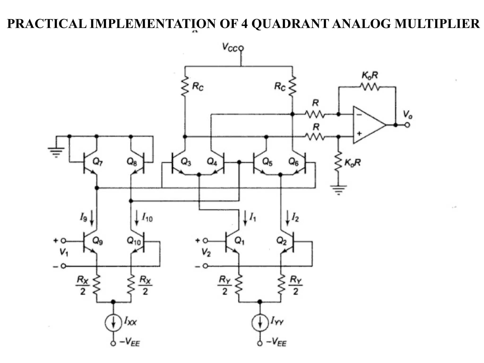
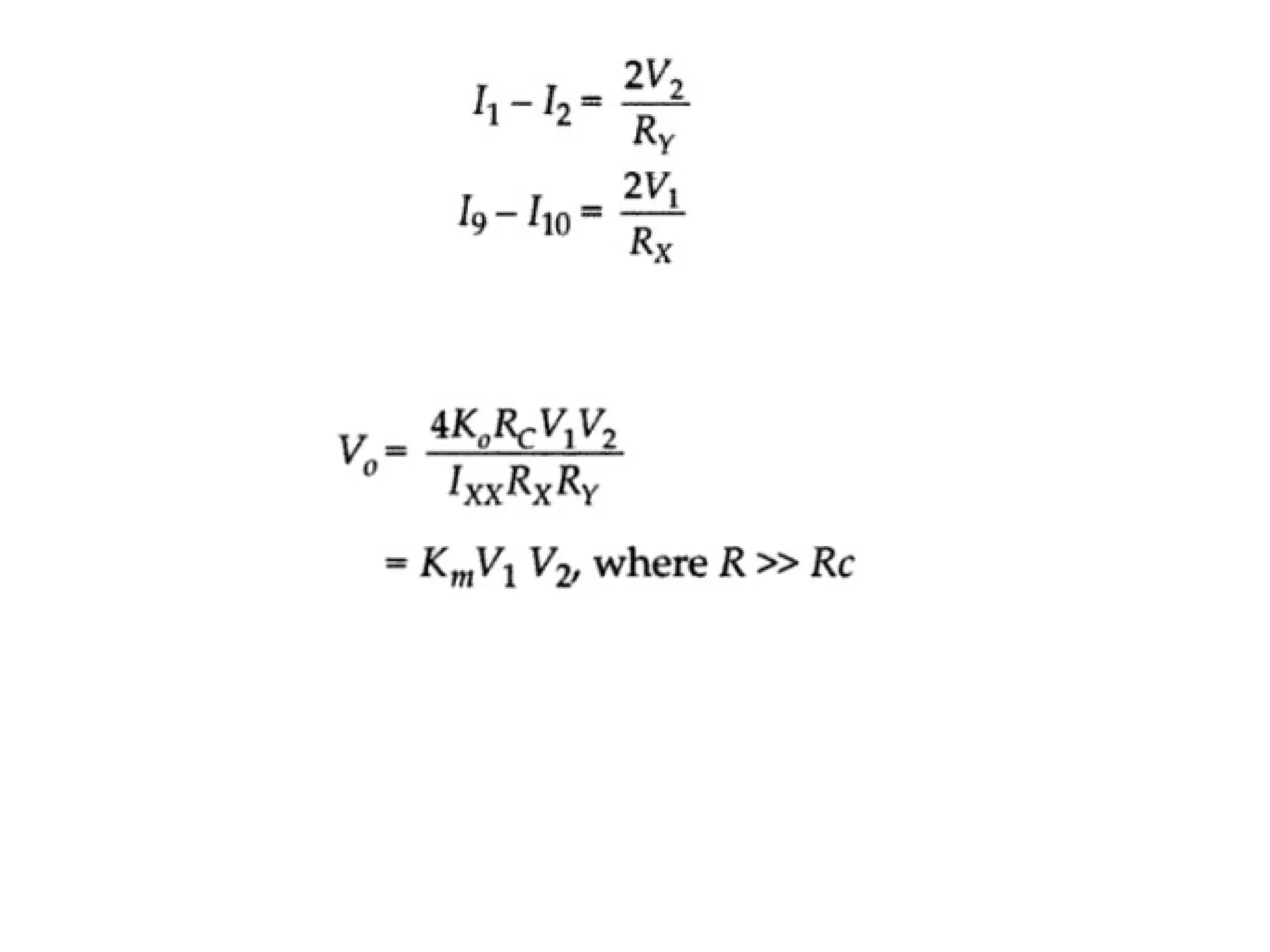
PRACTICAL IMPLEMENTATION OF 4 QUADRANT ANALOG MULTIPLIER
Variable Transconductance Technique
The variable transconductance technique makes use of the dependence
characteristic of the transistor transconductance parameter on the emitter current bias
applied. A simple differential circuit arrangement depicting the principle is shown in
figure.
0
( / )
m L x
y T E L x
x y L
T E
V g R V
V V R R V
V V R
V R



FOUR QUADRANT VARIABLE TRANSCONDUCTANCE MULTIPLIER
•The four quadrant operation indicates that the output voltage is
directly proportional to the product of the two input voltages
regardless of the polarity of the inputs and such multipliers can be
operated in all the four quadrants of operation.
•The first part of the circuit generates an intermediate voltage V1
across the transistors QA in response to the input signal Vx .
• The nonlinear response to the input Vx and QB in generating
V1 is compensated by the inverse nonlinearity associated with the
base – emitter junctions of the quad- transistors Q5 – Q6 and Q7 –
Q8 .
• Thus the output voltage Vz is maintained proportional to the linear
product of the two voltages. The emitter degeneration resistors Rx and
Ry provide linear conversion of the input voltages to differential
currents Ix and Iy.
UNIT 4 LIC notes on aqedhiohflcnlohnkjihiohykbl

UNIT 4 LIC notes on aqedhiohflcnlohnkjihiohykbl

  • 1.
    PRACTICAL IMPLEMENTATION OF4 QUADRANT ANALOG MULTIPLIER
  • 3.
  • 4.
    The variable transconductancetechnique makes use of the dependence characteristic of the transistor transconductance parameter on the emitter current bias applied. A simple differential circuit arrangement depicting the principle is shown in figure.
  • 5.
    0 ( / ) mL x y T E L x x y L T E V g R V V V R R V V V R V R   
  • 7.
    FOUR QUADRANT VARIABLETRANSCONDUCTANCE MULTIPLIER •The four quadrant operation indicates that the output voltage is directly proportional to the product of the two input voltages regardless of the polarity of the inputs and such multipliers can be operated in all the four quadrants of operation. •The first part of the circuit generates an intermediate voltage V1 across the transistors QA in response to the input signal Vx . • The nonlinear response to the input Vx and QB in generating V1 is compensated by the inverse nonlinearity associated with the base – emitter junctions of the quad- transistors Q5 – Q6 and Q7 – Q8 . • Thus the output voltage Vz is maintained proportional to the linear product of the two voltages. The emitter degeneration resistors Rx and Ry provide linear conversion of the input voltages to differential currents Ix and Iy.