Understanding Operating Systems 7th Edition McHoes Test Bank
Understanding Operating Systems 7th Edition McHoes Test Bank
Understanding Operating Systems 7th Edition McHoes Test Bank
Understanding Operating Systems 7th Edition McHoes Test Bank
Understanding Operating Systems 7th Edition McHoes Test Bank
1.
Understanding Operating Systems7th Edition
McHoes Test Bank download
https://testbankdeal.com/product/understanding-operating-
systems-7th-edition-mchoes-test-bank/
Explore and download more test bank or solution manual
at testbankdeal.com
2.
We believe theseproducts will be a great fit for you. Click
the link to download now, or visit testbankdeal.com
to discover even more!
Understanding Operating Systems 7th Edition McHoes
Solutions Manual
https://testbankdeal.com/product/understanding-operating-systems-7th-
edition-mchoes-solutions-manual/
Understanding Operating Systems 5th Edition McHoes Test
Bank
https://testbankdeal.com/product/understanding-operating-systems-5th-
edition-mchoes-test-bank/
Understanding Operating Systems 8th Edition McHoes
Solutions Manual
https://testbankdeal.com/product/understanding-operating-systems-8th-
edition-mchoes-solutions-manual/
Psychology in Everyday Life 4th Edition Myers Test Bank
https://testbankdeal.com/product/psychology-in-everyday-life-4th-
edition-myers-test-bank/
3.
International Economics 11thEdition Salvatore Test Bank
https://testbankdeal.com/product/international-economics-11th-edition-
salvatore-test-bank/
Beginning and Intermediate Algebra 5th Edition Elayn
Martin-Gay Test Bank
https://testbankdeal.com/product/beginning-and-intermediate-
algebra-5th-edition-elayn-martin-gay-test-bank/
Fundamentals of Corporate Finance Australian 3rd Edition
Berk Solutions Manual
https://testbankdeal.com/product/fundamentals-of-corporate-finance-
australian-3rd-edition-berk-solutions-manual/
College Algebra in Context 5th Edition Harshbarger
Solutions Manual
https://testbankdeal.com/product/college-algebra-in-context-5th-
edition-harshbarger-solutions-manual/
Principles of Finance 6th Edition Besley Test Bank
https://testbankdeal.com/product/principles-of-finance-6th-edition-
besley-test-bank/
4.
Psychology An Exploration2nd Edition Ciccarelli Test Bank
https://testbankdeal.com/product/psychology-an-exploration-2nd-
edition-ciccarelli-test-bank/
5.
Chapter 7: DeviceManagement
TRUE/FALSE
1. The universal serial bus (USB) controller acts as an interface between the operating system, device
drivers, applications, and the devices that are attached via the USB host.
ANS: T PTS: 1 REF: 211
2. Device management principles are changing rapidly to accommodate cloud computing.
ANS: F PTS: 1 REF: 213
3. Direct access storage devices (DASDs) are devices that can directly read or write to an arbitrary place
on a disk.
ANS: T PTS: 1 REF: 216
4. Seek time is the most important characteristic of a fixed-head disk drive.
ANS: F PTS: 1 REF: 218
5. A seek strategy for an I/O device handler is the predetermined policy that the device handler uses to
allocate access to the device among the many processes that may be waiting for it. It determines the
order in which the processes get the device; the goal is to keep transfer time to a minimum.
ANS: F PTS: 1 REF: 220
6. First-come, first-served (FCFS) is the simplest device-scheduling algorithm; it is easy to program and
essentially fair to users.
ANS: T PTS: 1 REF: 221
7. The Shortest Seek Time First device-scheduling algorithm moves the arm methodically from the inner
to the outer track, servicing every request in its path.
ANS: F PTS: 1 REF: 222
8. In the N-Step SCAN device-scheduling algorithm, any requests that arrive while the arm is in motion
are grouped for the arm’s next sweep.
ANS: T PTS: 1 REF: 224
9. There are many more sectors on an optical disc than on a magnetic disk of the same area.
ANS: T PTS: 1 REF: 227
10. An optical disc drive spins at a constant speed—this is called constant linear velocity.
ANS: F PTS: 1 REF: 227
6.
11. Two ofthe most important measures of optical disc drive performance are sustained data-transfer rate
and maximum access time.
ANS: F PTS: 1 REF: 228
12. A DVD with a fast data transfer rate will drop fewer frames when playing back a recorded video
segment than will a unit with a slower transfer rate.
ANS: T PTS: 1 REF: 228
13. Blu-ray discs are available in several formats: read-only (BD-ROM), recordable (BD-R), and
rewritable (BD-RE).
ANS: T PTS: 1 REF: 231
14. The job of the I/O control unit is to keep up with the I/O requests from the CPU and pass them down
the line to the appropriate control unit.
ANS: F PTS: 1 REF: 234
15. When using DMA, the CPU controls the transfer of data to and from memory over the system bus.
ANS: F PTS: 1 REF: 238
16. Buffers are used to synchronize the movement of data between the relatively slow I/O devices and the
very fast CPU.
ANS: T PTS: 1 REF: 238
17. RAID is a set of logical disk drives, viewed as a single physical unit by the operating system.
ANS: F PTS: 1 REF: 239
18. RAID begins with the assumption that a small set of large-capacity disk drives is preferable to a larger
set of small-capacity disk drives.
ANS: F PTS: 1 REF: 239
19. RAID Level 0 is not considered a true form of RAID because it cannot recover from hardware failure.
ANS: T PTS: 1 REF: 241
20. Nested RAID levels, also called hybrid levels, are complex RAID configurations created by combining
multiple standard levels.
ANS: T PTS: 1 REF: 245
MULTIPLE CHOICE
1. ____ peripheral devices are assigned to only one job at a time.
a. Dedicated c. Virtual
b. Shared d. Static
7.
ANS: A PTS:1 REF: 210
2. The USB controller assigns bandwidth to each device depending on its priority. The ____ priority is
assigned to real-time exchanges where no interruption in the data flow is allowed, such as video or
sound data.
a. highest c. lowest
b. medium d. standard
ANS: A PTS: 1 REF: 211
3. The I/O ____ allocates the devices, control units, and channels.
a. scheduler c. device handler
b. traffic controller d. director
ANS: A PTS: 1 REF: 212
4. The number of characters that can be recorded per inch on a magnetic tape is determined by the ____
of the tape.
a. width c. density
b. length d. parity
ANS: C PTS: 1 REF: 213
5. Transfer rate of a magnetic tape is measured in inches per second (ips) using the following formula:
transfer rate = density * ____.
a. block size c. transport speed
b. average access time d. sector size
ANS: C PTS: 1 REF: 215
6. If 2.5 minutes is the maximum access time for a magnetic tape, ____ is the average access time.
a. 0.5 minutes c. 1.25 minutes
b. 1 minute d. 2 minutes
ANS: C PTS: 1 REF: 216
7. Of the three components of access time in a movable-head DASD, ____ is the slowest.
a. seek time c. transfer time
b. search time d. delay time
ANS: A PTS: 1 REF: 218
8. ____ time is the time required to move the arm of a movable-head magnetic drive into position over
the proper track.
a. Search c. Transfer
b. Seek d. Access
ANS: B PTS: 1 REF: 220
9. ____ uses the same underlying philosophy as shortest job next, where the shortest jobs are processed
first and longer jobs are made to wait.
a. LOOK c. SSTF
b. FCFS d. SCAN
ANS: C PTS: 1 REF: 222
8.
10. ____ isa way to optimize search times on hard disk drives by ordering the requests once the read/write
heads have been positioned.
a. Rotational ordering c. C-SCAN
b. SSTF d. LOOK and SCAN
ANS: A PTS: 1 REF: 225
11. The advent of optical discs was made possible by developments in ____ technology.
a. magnetic c. storage
b. laser d. silicone
ANS: B PTS: 1 REF: 227
12. On an optical disc, all sectors are ____.
a. of varying sizes depending upon where you are on the disc
b. larger as you move to the edge
c. smaller as you move to the edge
d. of the same size throughout the disc
ANS: D PTS: 1 REF: 228
13. The data-transfer rate for an optical disc is measured in ____ per second and refers to the speed at
which massive amounts of data can be read from the disc.
a. kilobytes c. gigabytes
b. megabytes d. terabytes
ANS: B PTS: 1 REF: 228
14. To put data on an optical disc requires a high-intensity laser beam, which burns indentations, called
pits, and flat areas, called ____.
a. lands c. hills
b. valleys d. lakes
ANS: A PTS: 1 REF: 229
15. A dual-layer, single-sided DVD can hold the equivalent of ____ CDs.
a. 3 c. 13
b. 8 d. 19
ANS: C PTS: 1 REF: 230
16. To write data to flash memory, a relatively high voltage is sent through one transistor, called the ____,
then through a metal oxide layer and into a second transistor called the control gate, where the charge
is stored in a cell until it’s erased.
a. parallel port c. pit
b. floating gate d. crystalline port
ANS: B PTS: 1 REF: 231
17. ____ control the transfer of information between the disk drives and the rest of the computer system.
a. System controllers c. System interfaces
b. Disk drive controllers d. Disk drive interfaces
ANS: D PTS: 1 REF: 235
9.
18. The ____is a hardware flag that must be tested by the CPU to determine when a device has completed
an operation.
a. Channel Interrupt Word c. Device Status Word
b. Channel Status Word d. Device Polling Word
ANS: B PTS: 1 REF: 237
19. A ____, used in RAID Level 2, is a coding scheme that adds extra, redundant bits to the data and is
therefore able to correct single-bit errors and detect double-bit errors.
a. Synch code c. Parity code
b. Hamming code d. Redundancy code
ANS: B PTS: 1 REF: 243
20. RAID level ____ requires two different parity calculations.
a. 2 c. 5
b. 3 d. 6
ANS: D PTS: 1 REF: 245
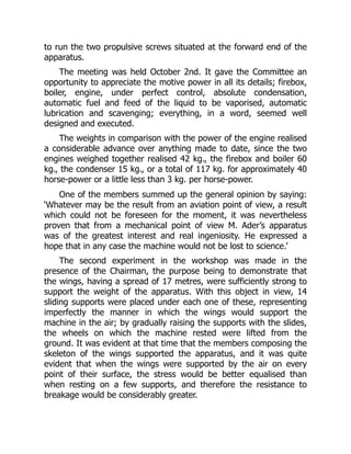
to run thetwo propulsive screws situated at the forward end of the
apparatus.
The meeting was held October 2nd. It gave the Committee an
opportunity to appreciate the motive power in all its details; firebox,
boiler, engine, under perfect control, absolute condensation,
automatic fuel and feed of the liquid to be vaporised, automatic
lubrication and scavenging; everything, in a word, seemed well
designed and executed.
The weights in comparison with the power of the engine realised
a considerable advance over anything made to date, since the two
engines weighed together realised 42 kg., the firebox and boiler 60
kg., the condenser 15 kg., or a total of 117 kg. for approximately 40
horse-power or a little less than 3 kg. per horse-power.
One of the members summed up the general opinion by saying:
‘Whatever may be the result from an aviation point of view, a result
which could not be foreseen for the moment, it was nevertheless
proven that from a mechanical point of view M. Ader’s apparatus
was of the greatest interest and real ingeniosity. He expressed a
hope that in any case the machine would not be lost to science.’
The second experiment in the workshop was made in the
presence of the Chairman, the purpose being to demonstrate that
the wings, having a spread of 17 metres, were sufficiently strong to
support the weight of the apparatus. With this object in view, 14
sliding supports were placed under each one of these, representing
imperfectly the manner in which the wings would support the
machine in the air; by gradually raising the supports with the slides,
the wheels on which the machine rested were lifted from the
ground. It was evident at that time that the members composing the
skeleton of the wings supported the apparatus, and it was quite
evident that when the wings were supported by the air on every
point of their surface, the stress would be better equalised than
when resting on a few supports, and therefore the resistance to
breakage would be considerably greater.
12.
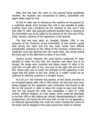
After this lasttest, the work on the ground being practically
finished, the machine was transported to Satory, assembled and
again made ready for trial.
At first M. Ader was to manœuvre the machine on the ground at
a moderate speed, then increase this until it was possible to judge
whether there was a tendency for the machine to rise; and it was
only after M. Ader had acquired sufficient practice that a meeting of
the Committee was to be called to be present at the first part of the
trials; namely, volutions of the apparatus on the ground.
The first test took place on Tuesday, October 12th, in the
presence of the Chairman of the Committee. It had rained a good
deal during the night and the clay track would have offered
considerable resistance to the rolling of the machine; furthermore, a
moderate wind was blowing from the south-west, too strong during
the early part of the afternoon to allow of any trials.
Toward sunset, however, the wind having weakened, M. Ader
decided to make his first trial; the machine was taken out of its
hangar, the wings were mounted and steam raised. M. Ader in his
seat had, on each side of him, one man to the right and one to the
left, whose duty was to rectify the direction of the apparatus in the
event that the action of the rear wheel as a rudder would not be
sufficient to hold the machine in a straight course.
At 5.25 p.m. the machine was started, at first slowly and then at
an increased speed; after 250 or 300 metres, the two men who were
being dragged by the apparatus were exhausted and forced to fall
flat on the ground in order to allow the wings to pass over them,
and the trip around the track was completed, a total of 1,400
metres, without incident, at a fair speed, which could be estimated
to be from 300 to 400 metres per minute. Notwithstanding M. Ader’s
inexperience, this being the first time that he had run his apparatus,
he followed approximately the chalk line which marked the centre of
the track and he stopped at the exact point from which he started.
13.
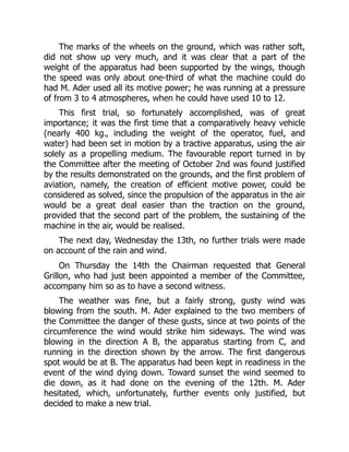
The marks ofthe wheels on the ground, which was rather soft,
did not show up very much, and it was clear that a part of the
weight of the apparatus had been supported by the wings, though
the speed was only about one-third of what the machine could do
had M. Ader used all its motive power; he was running at a pressure
of from 3 to 4 atmospheres, when he could have used 10 to 12.
This first trial, so fortunately accomplished, was of great
importance; it was the first time that a comparatively heavy vehicle
(nearly 400 kg., including the weight of the operator, fuel, and
water) had been set in motion by a tractive apparatus, using the air
solely as a propelling medium. The favourable report turned in by
the Committee after the meeting of October 2nd was found justified
by the results demonstrated on the grounds, and the first problem of
aviation, namely, the creation of efficient motive power, could be
considered as solved, since the propulsion of the apparatus in the air
would be a great deal easier than the traction on the ground,
provided that the second part of the problem, the sustaining of the
machine in the air, would be realised.
The next day, Wednesday the 13th, no further trials were made
on account of the rain and wind.
On Thursday the 14th the Chairman requested that General
Grillon, who had just been appointed a member of the Committee,
accompany him so as to have a second witness.
The weather was fine, but a fairly strong, gusty wind was
blowing from the south. M. Ader explained to the two members of
the Committee the danger of these gusts, since at two points of the
circumference the wind would strike him sideways. The wind was
blowing in the direction A B, the apparatus starting from C, and
running in the direction shown by the arrow. The first dangerous
spot would be at B. The apparatus had been kept in readiness in the
event of the wind dying down. Toward sunset the wind seemed to
die down, as it had done on the evening of the 12th. M. Ader
hesitated, which, unfortunately, further events only justified, but
decided to make a new trial.
14.
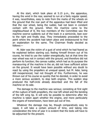
At the start,which took place at 5.15 p.m., the apparatus,
having the wind in the rear, seemed to run at a fairly regular speed;
it was, nevertheless, easy to note from the marks of the wheels on
the ground that the rear part of the apparatus had been lifted and
that the rear wheel, being the rudder, had not been in constant
contact with the ground. When the machine came to the
neighbourhood of B, the two members of the Committee saw the
machine swerve suddenly out of the track in a semicircle, lean over
to the right and finally stop. They immediately proceeded to the
point where the accident had taken place and endeavoured to find
an explanation for the same. The Chairman finally decided as
follows:—
M. Ader was the victim of a gust of wind which he had feared as
he explained before starting out; feeling himself thrown out of his
course, he tried to use the rudder energetically, but at that time the
rear wheel was not in contact with the ground, and therefore did not
perform its function; the canvas rudder, which had as its purpose the
manœuvring of the machine in the air, did not have sufficient action
on the ground. It would have been possible without any doubt to
react by using the propellers at unequal speed, but M. Ader, being
still inexperienced, had not thought of this. Furthermore, he was
thrown out of his course so quickly that he decided, in order to avoid
a more serious accident, to stop both engines. This sudden stop
produced the half-circle already described and the fall of the
machine on its side.
The damage to the machine was serious; consisting at first sight
of the rupture of both propellers, the rear left wheel and the bending
of the left wing tip. It will only be possible to determine after the
machine is taken apart whether the engine, and more particularly
the organs of transmission, have been put out of line.
Whatever the damage may be, though comparatively easy to
repair, it will take a certain amount of time, and taking into
consideration the time of year it is evident that the tests will have to
be adjourned for the present.
15.
As has beensaid in the above report, the tests, though
prematurely interrupted, have shown results of great importance,
and though the final results are hard to foresee, it would seem
advisable to continue the trials. By waiting for the return of spring
there will be plenty of time to finish the tests and it will not be
necessary to rush matters, which was a partial cause of the accident.
The Chairman of the Committee personally has but one hope, and
that is that a decision be reached accordingly.
Division General,
Chairman of the Committee,
Mensier.
Boulogne-sur-Seine, October 21st, 1897.
Annex to the Report of October 21st.
General Grillon, who was present at the trials of the 14th, and
who saw the report relative to what happened during that day, made
the following observations in writing, which are reproduced herewith
in quotation marks. The Chairman of the Committee does not agree
with General Grillon and he answers these observations paragraph
by paragraph.
1. ‘If the rear wheel (there is only one of these) left but
intermittent tracks on the ground, does that prove that the machine
has a tendency to rise when running at a certain speed?’
Answer.—This does not prove anything in any way, and I was
very careful not to mention this in my report, this point being exactly
what was needed and that was not demonstrated during the two
tests made on the grounds.
‘Does not this unequal pressure of the two pair of wheels on the
ground show that the centre of gravity of the apparatus is placed too
far forward and that under the impulse of the propellers the machine
has a tendency to tilt forward, due to the resistance of the air?’
16.
Answer.—The tendency ofthe apparatus to rise from the rear
when it was running with the wind seemed to be brought about by
the effects of the wind on the huge wings, having a spread of 17
metres, and I believe that when the machine would have faced the
wind the front wheels would have been lifted.
During the trials of October 12th, when a complete circuit of the
track was accomplished without incidents, as I and Lieut. Binet
witnessed, there was practically no wind. I was therefore unable to
verify whether during this circuit the two front wheels or the rear
wheel were in constant contact with the ground, because when the
trial was over it was dark (it was 5.30) and the next day it was
impossible to see anything because it had rained during the night
and during Wednesday morning. But what would prove that the rear
wheel was in contact with the ground at all times is the fact that M.
Ader, though inexperienced, did not swerve from the circular track,
which would prove that he steered pretty well with his rear wheel—
this he could not have done if he had been in the air.
In the tests of the 12th, the speed was at least as great as on
the 14th.
2. ‘It would seem to me that if M. Ader thought that his rear
wheels were off the ground he should have used his canvas rudder
in order to regain his proper course; this was the best way of
causing the machine to rotate, since it would have given an angular
motion to the front axle.’
Answer.—I state in my report that the canvas rudder whose
object was the manœuvre of the apparatus in the air could have no
effect on the apparatus on the ground, and to convince oneself of
this point it is only necessary to consider the small surface of this
canvas rudder compared with the mass to be handled on the
ground, a weight of approximately 400 kg. According to my idea,
and as I have stated in my report, M. Ader should have steered by
increasing the speed on one of his propellers and slowing down the
other. He admitted afterward that this remark was well founded, but
17.
that he didnot have time to think of it owing to the suddenness of
the accident.
3. ‘When the apparatus fell on its side it was under the sole
influence of the wind, since M. Ader had stopped the machine. Have
we not a result here which will always be the same when the
machine comes to the ground, since the engines will always have to
be stopped or slowed down when coming to the ground? Here
seems to be a bad defect of the apparatus under trial.’
Answer.—I believe that the apparatus fell on its side after
coming to a stop, not on account of the wind, but because the
semicircle described was on rough ground and one of the wheels
had collapsed.
Mensier.
October 27th, 1897.
18.
APPENDIX B
Specification andClaims of Wright Patent,
No. 821393. Filed March 23rd, 1903. Issued
May 22nd, 1906. Expires May 22nd, 1923.
To all whom it may concern.
Be it known that we, Orville Wright and Wilbur Wright, citizens
of the United States, residing in the city of Dayton, county of
Montgomery, and State of Ohio, have invented certain new and
useful Improvements in Flying Machines, of which the following is a
specification.
Our invention relates to that class of flying machines in which
the weight is sustained by the reactions resulting when one or more
aeroplanes are moved through the air edgewise at a small angle of
incidence, either by the application of mechanical power or by the
utilisation of the force of gravity.
The objects of our invention are to provide means for
maintaining or restoring the equilibrium or lateral balance of the
apparatus, to provide means for guiding the machine both vertically
and horizontally, and to provide a structure combining lightness,
strength, convenience of construction and certain other advantages
which will hereinafter appear.
To these ends our invention consists in certain novel features,
which we will now proceed to describe and will then particularly
point out in the claims.
19.
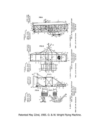
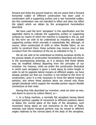
In the accompanyingdrawings, Figure 1 is a perspective view of
an apparatus embodying our invention in one form. Fig. 2 is a plan
view of the same, partly in horizontal section and partly broken
away. Fig. 3 is a side elevation, and Figs. 4 and 5 are detail views, of
one form of flexible joint for connecting the upright standards with
the aeroplanes.
In flying machines of the character to which this invention
relates the apparatus is supported in the air by reason of the contact
between the air and the under surface of one or more aeroplanes,
the contact surface being presented at a small angle of incidence to
the air. The relative movements of the air and aeroplane may be
derived from the motion of the air in the form of wind blowing in the
direction opposite to that in which the apparatus is travelling or by a
combined downward and forward movement of the machine, as in
starting from an elevated position or by combination of these two
things, and in either case the operation is that of a soaring-machine,
while power applied to the machine to propel it positively forward
will cause the air to support the machine in a similar manner. In
either case owing to the varying conditions to be met there are
numerous disturbing forces which tend to shift the machine from the
position which it should occupy to obtain the desired results. It is the
chief object of our invention to provide means for remedying this
difficulty, and we will now proceed to describe the construction by
means of which these results are accomplished.
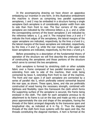
In the accompanyingdrawing we have shown an apparatus
embodying our invention in one form. In this illustrative embodiment
the machine is shown as comprising two parallel superposed
aeroplanes, 1 and 2 may be embodied in a structure having a single
aeroplane Each aeroplane is of considerably greater width from side
to side than from front to rear. The four corners of the upper
aeroplane are indicated by the reference letters a, b, c, and d, while
the corresponding corners of the lower aeroplane 2 are indicated by
the reference letters e, f, g, and h. The marginal lines a b and e f
indicate the front edges of the aeroplanes, the lateral margins of the
upper aeroplane are indicated, respectively, by the lines a d and b c,
the lateral margins of the lower aeroplane are indicated, respectively,
by the lines e h and f g, while the rear margins of the upper and
lower aeroplanes are indicated, respectively, by the lines c d and g h.
Before proceeding to a description of the fundamental theory of
operation of the structure we will first describe the preferred mode
of constructing the aeroplanes and those portions of the structure
which serve to connect the two aeroplanes.
Each aeroplane is formed by stretching cloth or other suitable
fabric over a frame composed of two parallel transverse spars 3,
extending from side to side of the machine, their ends being
connected by bows 4, extending from front to rear of the machine.
The front and rear spars 3 of each aeroplane are connected by a
series of parallel ribs 5, which preferably extend somewhat beyond
the rear spar, as shown. These spars, bows, and ribs are preferably
constructed of wood having the necessary strength, combined with
lightness and flexibility. Upon this framework the cloth which forms
the supporting surface of the aeroplane is secured, the frame being
enclosed in the cloth. The cloth for each aeroplane previous to its
attachment to its frame is cut on the bias and made up into a single
piece approximately the size and shape of the aeroplane, having the
threads of the fabric arranged diagonally to the transverse spars and
longitudinal ribs, as indicated at 6 in Fig. 2. Thus the diagonal
threads of the cloth form truss systems with the spars and ribs, the
threads constituting the diagonal members. A hem is formed at the
22.
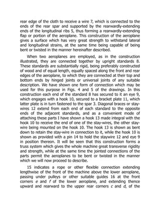
rear edge ofthe cloth to receive a wire 7, which is connected to the
ends of the rear spar and supported by the rearwardly-extending
ends of the longitudinal ribs 5, thus forming a rearwardly-extending
flap or portion of the aeroplane. This construction of the aeroplane
gives a surface which has very great strength to withstand lateral
and longitudinal strains, at the same time being capable of being
bent or twisted in the manner hereinafter described.
When two aeroplanes are employed, as in the construction
illustrated, they are connected together by upright standards 8.
These standards are substantially rigid, being preferably constructed
of wood and of equal length, equally spaced along the front and rear
edges of the aeroplane, to which they are connected at their top and
bottom ends by hinged joints or universal joints of any suitable
description. We have shown one form of connection which may be
used for this purpose in Figs. 4 and 5 of the drawings. In this
construction each end of the standard 8 has secured to it an eye 9,
which engages with a hook 10, secured to a bracket plate 11, which
latter plate is in turn fastened to the spar 3. Diagonal braces or stay-
wires 12 extend from each end of each standard to the opposite
ends of the adjacent standards, and as a convenient mode of
attaching these parts I have shown a hook 13 made integral with the
hook 10 to receive the end of one of the stay-wires, the other stay-
wire being mounted on the hook 10. The hook 13 is shown as bent
down to retain the stay-wire in connection to it, while the hook 10 is
shown as provided with a pin 14 to hold the staywire 12 and eye 9
in position thereon. It will be seen that this construction forms a
truss system which gives the whole machine great transverse rigidity
and strength, while at the same time the jointed connections of the
parts permit the aeroplanes to be bent or twisted in the manner
which we will now proceed to describe.
15 indicates a rope or other flexible connection extending
lengthwise of the front of the machine above the lower aeroplane,
passing under pulleys or other suitable guides 16 at the front
corners e and f of the lower aeroplane, and extending thence
upward and rearward to the upper rear corners c and d, of the
23.
upper aeroplane, wherethey are attached, as indicated at 17. To the
central portion of the rope there is connected a laterally-movable
cradle 18, which forms a means for moving the rope lengthwise in
one direction or the other, the cradle being movable toward either
side of the machine. We have devised this cradle as a convenient
means for operating the rope 15, and the machine is intended to be
generally used with the operator lying face downward on the lower
aeroplane, with his head to the front, so that the operator’s body
rests on the cradle, and the cradle can be moved laterally by the
movements of the operator’s body. It will be understood, however,
that the rope 15 may be manipulated in any suitable manner.
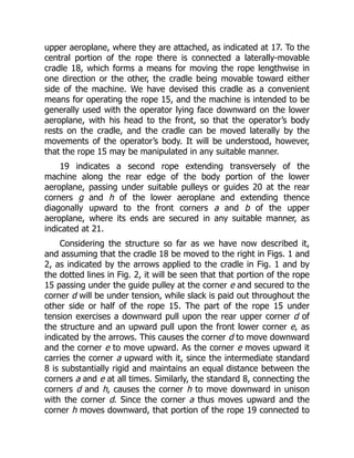
19 indicates a second rope extending transversely of the
machine along the rear edge of the body portion of the lower
aeroplane, passing under suitable pulleys or guides 20 at the rear
corners g and h of the lower aeroplane and extending thence
diagonally upward to the front corners a and b of the upper
aeroplane, where its ends are secured in any suitable manner, as
indicated at 21.
Considering the structure so far as we have now described it,
and assuming that the cradle 18 be moved to the right in Figs. 1 and
2, as indicated by the arrows applied to the cradle in Fig. 1 and by
the dotted lines in Fig. 2, it will be seen that that portion of the rope
15 passing under the guide pulley at the corner e and secured to the
corner d will be under tension, while slack is paid out throughout the
other side or half of the rope 15. The part of the rope 15 under
tension exercises a downward pull upon the rear upper corner d of
the structure and an upward pull upon the front lower corner e, as
indicated by the arrows. This causes the corner d to move downward
and the corner e to move upward. As the corner e moves upward it
carries the corner a upward with it, since the intermediate standard
8 is substantially rigid and maintains an equal distance between the
corners a and e at all times. Similarly, the standard 8, connecting the
corners d and h, causes the corner h to move downward in unison
with the corner d. Since the corner a thus moves upward and the
corner h moves downward, that portion of the rope 19 connected to
24.
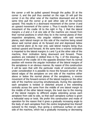
the corner awill be pulled upward through the pulley 20 at the
corner h, and the pull thus exerted on the rope 19 will pull the
corner b on the other wise of the machine downward and at the
same time pull the corner g at said other side of the machine
upward. This results in a downward movement of the corner b and
an upward movement of the corner c. Thus it results from a lateral
movement of the cradle 18 to the right in Fig. 1 that the lateral
margins a d and e h at one side of the machine are moved from
their normal positions in which they lie in the normal planes of their
respective aeroplanes, into angular relations with said normal
planes, each lateral margin on this side of the machine being raised
above said normal plane at its forward end and depressed below
said normal plane at its rear end, said lateral margins being thus
inclined upward and forward. At the same time a reverse inclination
is imparted to the lateral margins b c and f g at the other side of the
machine, their inclination being downward and forward. These
positions are indicated in dotted lines in Fig. 1 of the drawings. A
movement of the cradle 18 in the opposite direction from its normal
position will reverse the angular inclination of the lateral margins of
the aeroplanes in an obvious manner. By reason of this construction
it will be seen that with the particular mode of construction now
under consideration it is possible to move the forward corner of the
lateral edges of the aeroplane on one side of the machine either
above or below the normal planes of the aeroplanes, a reverse
movement of the forward corners of the lateral margins on the other
side of the machine occurring simultaneously. During this operation
each aeroplane is twisted or distorted around a line extending
centrally across the same from the middle of one lateral margin to
the middle of the other lateral margin, the twist due to the moving
of the lateral margins to different angles extending across each
aeroplane from side to side, so that each aeroplane surface is given
a helicoidal warp or twist. We prefer this construction and mode of
operation for the reason that it gives a gradually increasing angle to
the body of each aeroplane from the centre longitudinal line thereof
outward to the margin, thus giving a continuous surface on each
side of the machine, which has a gradually increasing or decreasing
25.
angle of incidencefrom the centre of the machine to either side. We
wish it to be understood, however, that our invention is not limited
to this particular construction, since any construction whereby the
angular relations of the lateral margins of the aeroplanes may be
varied in opposite directions with respect to the normal planes of
said aeroplanes comes within the scope of our invention.
Furthermore, it should be understood that while the lateral margins
of the aeroplanes move to different angular positions with respect to
or above and below the normal planes of said aeroplanes, it does
not necessarily follow that these movements bring the opposite
lateral edges to different angles respectively above and below a
horizontal plane, since the normal planes of the bodies of the
aeroplanes are inclined to the horizontal when the machine is in
flight, said inclination being downward from front to rear, and while
the forward corners on one side of the machine may be depressed
below the normal planes of the bodies of the aeroplanes said
depression is not necessarily sufficient to carry them below the
horizontal planes passing through the rear corners on that side.
Moreover, although we prefer to so construct the apparatus that the
movements of the lateral margins on the opposite sides of the
machine are equal in extent and opposite in direction, yet our
invention is not limited to a construction producing this result, since
it may be desirable under certain circumstances to move the lateral
margins on one side of the machine just described without moving
the lateral margins on the other side of the machine to an equal
extent in the opposite direction. Turning now to the purpose of this
provision for moving the lateral margins of the aeroplanes in the
manner described, it should be premised that owing to various
conditions of wind pressure and other causes the body of the
machine is apt to become unbalanced laterally, one side tending to
sink and the other side tending to rise, the machine turning around
its central longitudinal axis. The provision which we have just
described enables the operator to meet this difficulty and preserve
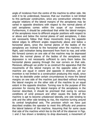
the lateral balance of the machine. Assuming that for some cause
that side of the machine which lies to the left of the observer in Figs.
1 and 2 has shown a tendency to drop downward, a movement of
26.
the cradle 18to the right of said figures, as hereinbefore assumed,
will move the lateral margins of the aeroplanes in the manner
already described, so that the margins a d and e h will be inclined
downward and rearward, and the lateral margins b c and f g will be
inclined upward and rearward with respect to the normal planes of
the bodies of the aeroplanes. With the parts of the machine in this
position it will be seen that the lateral margins a d and e h present a
larger angle of incidence to the resisting air, while the lateral margins
on the other side of the machine present a smaller angle of
incidence. Owing to this fact, the side of the machine presenting the
larger angle of incidence will tend to lift or move upward, and this
upward movement will restore the lateral balance of the machine.
When the other side of the machine tends to drop, a movement of
the cradle 18 in the reverse direction will restore the machine to its
normal lateral equilibrium. Of course, the same effect will be
produced in the same way in the case of a machine employing only
a single aeroplane.
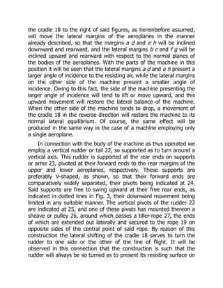
In connection with the body of the machine as thus operated we
employ a vertical rudder or tail 22, so supported as to turn around a
vertical axis. This rudder is supported at the rear ends on supports
or arms 23, pivoted at their forward ends to the rear margins of the
upper and lower aeroplanes, respectively. These supports are
preferably V-shaped, as shown, so that their forward ends are
comparatively widely separated, their pivots being indicated at 24.
Said supports are free to swing upward at their free rear ends, as
indicated in dotted lines in Fig. 3, their downward movement being
limited in any suitable manner. The vertical pivots of the rudder 22
are indicated at 25, and one of these pivots has mounted thereon a
sheave or pulley 26, around which passes a tiller-rope 27, the ends
of which are extended out laterally and secured to the rope 19 on
opposite sides of the central point of said rope. By reason of this
construction the lateral shifting of the cradle 18 serves to turn the
rudder to one side or the other of the line of flight. It will be
observed in this connection that the construction is such that the
rudder will always be so turned as to present its resisting surface on
27.
that side ofthe machine on which the lateral margins of the
aeroplanes present the least angle of resistance. The reason of this
construction is that when the lateral margins of the aeroplanes are
so turned in the manner hereinbefore described as to present
different angles of incidence to the atmosphere, that side presenting
the largest angle of incidence, although being lifted or moved
upward in the manner already described, at the same time meets
with an increased resistance to its forward motion, while at the same
time the other side of the machine, presenting a smaller angle of
incidence, meets with less resistance to its forward motion and tends
to move forward more rapidly than the retarded side. This gives the
machine a tendency to turn around its vertical axis, and this
tendency if not properly met will not only change the direction of the
front of the machine, but will ultimately permit one side thereof to
drop into a position vertically below the other side with the
aeroplanes in vertical position, thus causing the machine to fall. The
movement of the rudder, hereinbefore described, prevents this
action, since it exerts a retarding influence on that side of the
machine which tends to move forward too rapidly and keeps the
machine with its front properly presented to the direction of flight
and with its body properly balanced around its central longitudinal
axis. The pivoting of the supports 23 so as to permit them to swing
upward prevents injury to the rudder and its supports in case the
machine alights at such an angle as to cause the rudder to strike the
ground first, the parts yielding upward, as indicated in dotted lines in
Fig. 3, and thus preventing injury or breakage. We wish it to be
understood, however, that we do not limit ourselves to the particular
description of rudder set forth, the essential being that the rudder
shall be vertical and shall be so moved as to present its resisting
surface on that side of the machine which offers the least resistance
to the atmosphere, so as to counteract the tendency of the machine
to turn around a vertical axis when the two sides thereof offer
different resistances to the air.
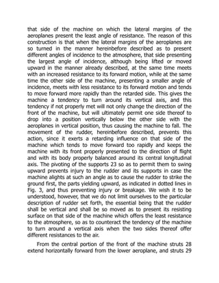
From the central portion of the front of the machine struts 28
extend horizontally forward from the lower aeroplane, and struts 29
28.
extend downward andforward from the central portion of the upper
aeroplane, their front ends being united to the struts 28, the forward
extremities of which are turned up, as indicated at 30. These struts
28 and 29 form truss-skids projecting in front of the whole frame of
the machine and serving to prevent the machine from rolling over
forward when it alights. The struts 29 serve to brace the upper
portion of the main frame and resist its tendency to move forward
after the lower aeroplane has been stopped by its contact with the
earth, thereby relieving the rope 19 from undue strain, for it will be
understood that when the machine comes into contact with the
earth, further forward movement of the lower portion thereof being
suddenly arrested, the inertia of the upper portion would tend to
cause it to continue to move forward if not prevented by the struts
29, and this forward movement of the upper portion would bring a
very violent strain upon the rope 19, since it is fastened to the upper
portion at both of its ends, while its lower portion is connected by
the guides 20 to the lower portion. The struts 28 and 29 also serve
to support the front or horizontal rudder, the construction of which
we will now proceed to describe.
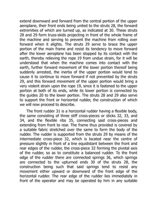
The front rudder 31 is a horizontal rudder having a flexible body,
the same consisting of three stiff cross-pieces or sticks 32, 33, and
34, and the flexible ribs 35, connecting said cross-pieces and
extending from front to rear. The frame thus provided is covered by
a suitable fabric stretched over the same to form the body of the
rudder. The rudder is supported from the struts 29 by means of the
intermediate cross-piece 32, which is located near the centre of
pressure slightly in front of a line equidistant between the front and
rear edges of the rudder, the cross-piece 32 forming the pivotal axis
of the rudder, so as to constitute a balanced rudder. To the front
edge of the rudder there are connected springs 36, which springs
are connected to the upturned ends 30 of the struts 28, the
construction being such that said springs tend to resist any
movement either upward or downward of the front edge of the
horizontal rudder. The rear edge of the rudder lies immediately in
front of the operator and may be operated by him in any suitable
29.
manner. We haveshown a mechanism for this purpose comprising a
roller or shaft 37, which may be grasped by the operator so as to
turn the same in either direction. Bands 38 extend from the roller 37
forward to and around a similar roller or shaft 39, both rollers or
shafts being supported in suitable bearings on the struts 28. The
forward roller or shaft has rearwardly-extending arms 40, which are
connected by links 41 with the rear edge of the rudder 31. The
normal position of the rudder 31 is neutral or substantially parallel
with the aeroplanes 1 and 2; but its rear edge may be moved
upward or downward, so as to be above or below the normal plane
of said rudder through the mechanism provided for that purpose. It
will be seen that the springs 36 will resist any tendency of the
forward edge of the rudder to move in either direction, so that when
force is applied to the rear edge of said rudder the longitudinal ribs
35 bend, and the rudder thus presents a concave surface to the
action of the wind either above or below its normal plane, said
surface presenting a small angle of incidence at its forward portion
and said angle of incidence rapidly increasing toward the rear. This
greatly increases the efficiency of the rudder as compared with a
plane surface of equal area. By regulating the pressure on the upper
and lower sides of the rudder through changes of angle and
curvature in the manner described a turning movement of the main
structure around its transverse axis may be effected, and the course
of the machine may thus be directed upward or downward at the
will of the operator and the longitudinal balance thereof maintained.
Contrary to the usual custom, we place the horizontal rudder in
front of the aeroplanes at a negative angle and employ no horizontal
tail at all. By this arrangement we obtain a forward surface which is
almost entirely free from pressure under ordinary conditions of
flight, but which even if not moved at all from its original position
becomes an efficient lifting surface whenever the speed of the
machine is accidentally reduced very much below the normal, and
thus largely counteracts that backward travel of the centre of
pressure on the aeroplanes which has frequently been productive of
serious injuries by causing the machine to turn downward and
30.
forward and strikethe ground head-on. We are aware that a forward
horizontal rudder of different construction has been used in
combination with a supporting surface and a rear horizontal rudder;
but this combination was not intended to effect and does not effect
the object which we obtain by the arrangement hereinbefore
described.
We have used the term ‘aeroplane’ in this specification and the
appended claims to indicate the supporting surface or supporting
surfaces by means of which the machine is sustained in the air, and
by this term we wish to be understood as including any suitable
supporting surface which normally is substantially flat, although, of
course, when constructed of cloth or other flexible fabric, as we
prefer to construct them, these surfaces may receive more or less
curvature from the resistance of the air, as indicated in Fig. 3.
We do not wish to be understood as limiting ourselves strictly to
the precise details of construction hereinbefore described and shown
in the accompanying drawings, as it is obvious that these details
may be modified without departing from the principles of our
invention. For instance, while we prefer the construction illustrated
in which each aeroplane is given a twist along its entire length in
order to set its opposite lateral margins at different angles, we have
already pointed out that our invention is not limited to this form of
construction, since it is only necessary to move the lateral marginal
portions, and where these portions alone are moved only those
upright standards which support the movable portion require flexible
connections at their ends.
Having thus fully described our invention, what we claim as new,
and desire to secure by Letters Patent, is:—
1. In a flying machine, a normally flat aeroplane having lateral
marginal portions capable of movement to different positions above
or below the normal plane of the body of the aeroplane, such
movement being about an axis transverse to the line of flight,
whereby said lateral marginal portions may be moved to different
angles relatively to the normal plane of the body of the aeroplane,
31.
so as topresent to the atmosphere different angles of incidence, and
means for so moving said lateral marginal portions, substantially as
described.
2. In a flying machine, the combination, with two normally
parallel aeroplanes, superposed the one above the other, of upright
standards connecting said planes at their margins, the connections
between the standards and aeroplanes at the lateral portions of the
aeroplanes being by means of flexible joints, each of said aeroplanes
having lateral marginal portions capable of movement to different
positions above or below the normal plane of the body of the
aeroplane, such movement being about an axis transverse to the
line of flight, whereby said lateral marginal portions may be moved
to different angles relatively to the normal plane of the body of the
aeroplane, so as to present to the atmosphere different angles of
incidence, the standards maintaining a fixed distance between the
portions of the aeroplanes which they connect, and means for
imparting such movement to the lateral marginal portions of the
aeroplanes, substantially as described.
3. In a flying machine, a normally flat aeroplane having lateral
marginal portions capable of movement to different positions above
or below the normal plane of the body of the aeroplane, such
movement being about an axis transverse to the line of flight,
whereby said lateral marginal portions may be moved to different
angles relatively to the normal plane of the body of the aeroplane,
and also to different angles relatively to each other, so as to present
to the atmosphere different angles of incidence, and means for
simultaneously imparting such movement to said lateral marginal
portions, substantially as described.
4. In a flying machine, the combination, with parallel superposed
aeroplanes, each having lateral marginal portions capable of
movement to different positions above or below the normal plane of
the body of the aeroplane, such movement being about an axis
transverse to the line of flight, whereby said lateral marginal portions
may be moved to different angles relatively to the normal plane of
32.
the body ofthe aeroplane, and to different angles relatively to each
other, so as to present to the atmosphere different angles of
incidence, of uprights connecting said aeroplanes at their edges, the
uprights connecting the lateral portions of the aeroplanes being
connected with said aeroplanes by flexible joints, and means for
simultaneously imparting such movement to said lateral marginal
portions, the standards maintaining a fixed distance between the
parts which they connect, whereby the lateral portions on the same
side of the machine are moved to the same angle, substantially as
described.
5. In a flying machine, an aeroplane having substantially the
form of a normally flat rectangle elongated transversely to the line of
flight, in combination which means for imparting to the lateral
margins of said aeroplane a movement about an axis lying in the
body of the aeroplane perpendicular to said lateral margins, and
thereby moving said lateral margins into different angular relations
to the normal plane of the body of the aeroplane, substantially as
described.
6. In a flying machine, the combination, with two superposed
and normally parallel aeroplanes, each having substantially the form
of a normally flat rectangle elongated transversely to the line of
flight, of upright standards connecting the edges of said aeroplanes
to maintain their equidistance, those standards at the lateral
portions of said aeroplanes being connected therewith by flexible
joints, and means for simultaneously imparting to both lateral
margins of both aeroplanes movement about axes which are
perpendicular to said margins and in the planes of the bodies of the
respective aeroplanes, and thereby moving the lateral margins on
the opposite sides of the machine into different angular relations to
the normal planes of the respective aeroplanes, the margins on the
same side of the machine moving to the same angle, and the
margins on one side of the machine moving to an angle different
from the angle to which the margins on the other side of the
machine move, substantially as described.
33.
7. In aflying machine, the combination, with an aeroplane, and
means for simultaneously moving the lateral portions thereof into
different angular relations to the normal plane of the body of the
aeroplane and to each other, so as to present to the atmosphere
different angles of incidence, of a vertical rudder, and means
whereby said rudder is caused to present to the wind that side
thereof nearest the side of the aeroplane having the smaller angle of
incidence and offering the least resistance to the atmosphere,
substantially as described.
8. In a flying machine, the combination, with two superposed
and normally parallel aeroplanes, upright standards connecting the
edges of said aeroplanes to maintain their equidistance, those
standards at the lateral portions of said aeroplanes being connected
therewith by flexible joints, and means for simultaneously moving
both lateral portions of both aeroplanes into different angular
relations to the normal planes of the bodies of the respective
aeroplanes, the lateral portions on one side of the machine being
moved to an angle different from that to which the lateral portions
on the other side of the machine are moved, so as to present
different angles of incidence at the two sides of the machine, of a
vertical rudder, and means whereby said rudder is caused to present
to the wind that side thereof nearest the side of the aeroplanes
having the smaller angle of incidence and offering the least
resistance to the atmosphere, substantially as described.
9. In a flying machine, an aeroplane normally flat and elongated
transversely to the line of flight, in combination with means for
imparting to said aeroplane a helicoidal warp around an axis
transverse to the line of flight and extending centrally along the
body of the aeroplane in the direction of the elongation of the
aeroplane, substantially as described.
10. In a flying machine, two aeroplanes, each normally flat and
elongated transversely to the line of flight, and upright standards
connecting the edges of said aeroplanes to maintain their
equidistance, the connections between said standards and
34.
aeroplanes being bymeans of flexible joints, in combination with
means for simultaneously imparting to each of said aeroplanes a
helicoidal warp around an axis transverse to the line of flight and
extending centrally along the body of the aeroplane in the direction
of the aeroplane, substantially as described.
11. In a flying machine, two aeroplanes, each normally flat and
elongated transversely to the line of flight, and upright standards
connecting the edges of said aeroplanes to maintain their
equidistance, the connections between such standards and
aeroplanes being by means of flexible joints, in combination with
means for simultaneously imparting to each of said aeroplanes a
helicoidal warp around an axis transverse to the line of flight and
extending centrally along the body of the aeroplane in the direction
of the elongation of the aeroplane, a vertical rudder, and means
whereby said rudder is caused to present to the wind that side
thereof nearest the side of the aeroplanes having the smaller angle
of incidence and offering the least resistance to the atmosphere,
substantially as described.
12. In a flying machine, the combination, with an aeroplane, of a
normally flat and substantially horizontal flexible rudder, and means
for curving said rudder rearwardly and upwardly or rearwardly and
downwardly with respect to its normal plane, substantially as
described.
13. In a flying machine, the combination, with an aeroplane, of a
normally flat and substantially horizontal flexible rudder pivotally
mounted on an axis transverse to the line of flight near its centre,
springs resisting vertical movement of the front edge of said rudder,
and means for moving the rear edge of said rudder, above or below
the normal plane thereof, substantially as described.
14. A flying machine comprising superposed connected
aeroplanes means for moving the opposite lateral portions of said
aeroplanes to different angles to the normal planes thereof, a
vertical rudder, means for moving said vertical rudder toward that
side of the machine presenting the smaller angle of incidence and
35.
the least resistanceto the atmosphere, and a horizontal rudder
provided with means for presenting its upper or under surface to the
resistance of the atmosphere, substantially as described.
15. A flying machine comprising superposed connected
aeroplanes, means for moving the opposite lateral portions of said
aeroplanes to different angles to the normal planes thereof, a
vertical rudder, means for moving said vertical rudder toward that
side of the machine presenting the smaller angle of incidence and
the least resistance to the atmosphere, and a horizontal rudder
provided with means for presenting its upper or under surface to the
resistance of the atmosphere, said vertical rudder being located at
the rear of the machine and said horizontal rudder at the front of the
machine, substantially as described.
16. In a flying machine, the combination, with two superposed
and connected aeroplanes, of an arm extending rearward from each
aeroplane, said arms being parallel and free to swing upward at their
rear ends, and a vertical rudder pivotally mounted in the rear ends
of said arms, substantially as described.
17. A flying machine comprising two superposed aeroplanes,
normally flat but flexible, upright standards connecting the margins
of said aeroplanes, said standards being connected to said
aeroplanes by universal joints, diagonal stay-wires connecting the
opposite ends of the adjacent standards, a rope extending along the
front edge of the lower aeroplane, passing through guides at the
front corners thereof, and having its ends secured to the rear
corners of the upper aeroplane, and a rope extending along the rear
edge of the lower aeroplane, passing through guides at the rear
corners thereof, and having its ends secured to the front corners of
the upper aeroplane, substantially as described.
18. A flying machine comprising two superposed aeroplanes,
normally flat but flexible, upright standards connecting the margins
of said aeroplanes, said standards being connected to said
aeroplanes by universal joints, diagonal stay-wires connecting the
opposite ends of the adjacent standards, a rope extending along the
36.
Welcome to ourwebsite – the perfect destination for book lovers and
knowledge seekers. We believe that every book holds a new world,
offering opportunities for learning, discovery, and personal growth.
That’s why we are dedicated to bringing you a diverse collection of
books, ranging from classic literature and specialized publications to
self-development guides and children's books.
More than just a book-buying platform, we strive to be a bridge
connecting you with timeless cultural and intellectual values. With an
elegant, user-friendly interface and a smart search system, you can
quickly find the books that best suit your interests. Additionally,
our special promotions and home delivery services help you save time
and fully enjoy the joy of reading.
Join us on a journey of knowledge exploration, passion nurturing, and
personal growth every day!
testbankdeal.com