

Recommended
More Related Content
Viewers also liked
Similar to Umesh
Similar to Umesh (20)
Recently uploaded
Recently uploaded (20)
Umesh
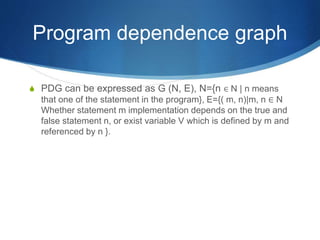
- 1. Program dependence graph PDG can be expressed as G (N, E), N={n ∈ N | n means that one of the statement in the program}, E={( m, n)|m, n ∈ N Whether statement m implementation depends on the true and false statement n, or exist variable V which is defined by m and referenced by n }.
- 2. Program dependence graph In the PDG there exist two kinds of dependence: One is control dependence, it describes in a program the conditional statements and circular statements with the statements embedded in them, their control relationships. The other kind is data dependence, it describes in the assignment statements the left value to the right value dependence relationship.
- 3. Program dependence graph Example for program and its PDG: void sum{ int i, sum; sum=0; i=1; while(i<11){ sum=sum+i; i=i+1; }}
- 4. Program dependence graph Result : void sum{ int i; i=1; while(i<11){ i=i+1; }} We just need to left the nodes which on the left side of assignment statement contains variable i.
- 5. • Each PDG has nodes for – entry point – procedure parameters and function result • Each call site has nodes for – call – arguments and function result • Appropriate edges – entry node to parameters – call node to arguments – call node to entry node – arguments to parameters How is an SDG Created?
- 6. SDG for the Sum Program Enter main sum = 0 i = 1 while(i < 11) printf(sum) printf(i) Call add Call add xin = sum yin = i sum = xout xin = i yin= 1 i = xout Enter add x = xin y = yin x = x + y xout = x
- 7. System dependence graph PDG is usually used to describe a single application of the process, but in the actual software development, there are few program contains only one single process, the program is usually composed of multiple processes. We need a new structure to reflect multiple processes program, so SDG could describe it.
- 8. System dependence graph We should not only consider the interdependencies of statements within process, but also to consider the invocation of the relationship between process and process, process parameters between transitive relation, etc. SDG is extended by PDG, it can be expressed as PDG and a series of process get together as a set.
- 9. System dependence graph Through the following steps to construct a system dependence graph, first of all, on the basis of PDG increased some new nodes: (1) For each of the called process set an Entry node (2) For each argument set an Actual - in node finally set an Actual - out node together, their relationship with the call statement is control dependence. (3) For each parameter set a Formal - in node, if the parameter value is changed in the procedure call, then again for this row and add a Formal - out node.
- 10. The dependence relationship between new nodes and original nodes Called statement node Actual-in node Actual-out node Process Entry node Formal-out node Process Entry node Call relationship N/A N/A N/A N/A Actual-in node Control dependenc e N/A N/A N/A N/A Actual-out node Control dependenc e Summary relationship Summary relationship N/A Formal-in node N/A Parameter- in(data dependenc Parameter- in(data dependenc Control dependenc e Parameter- in(data dependence)
- 14. END