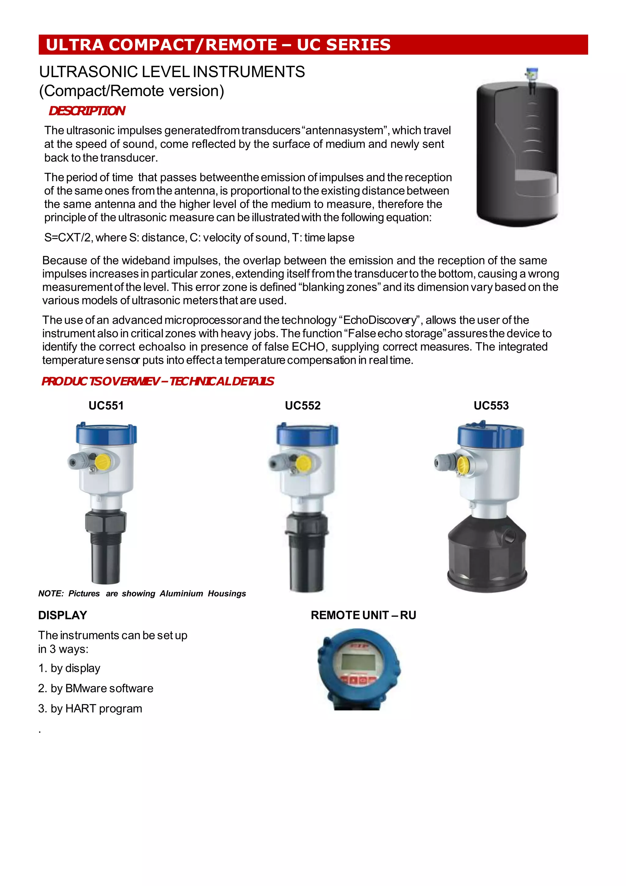
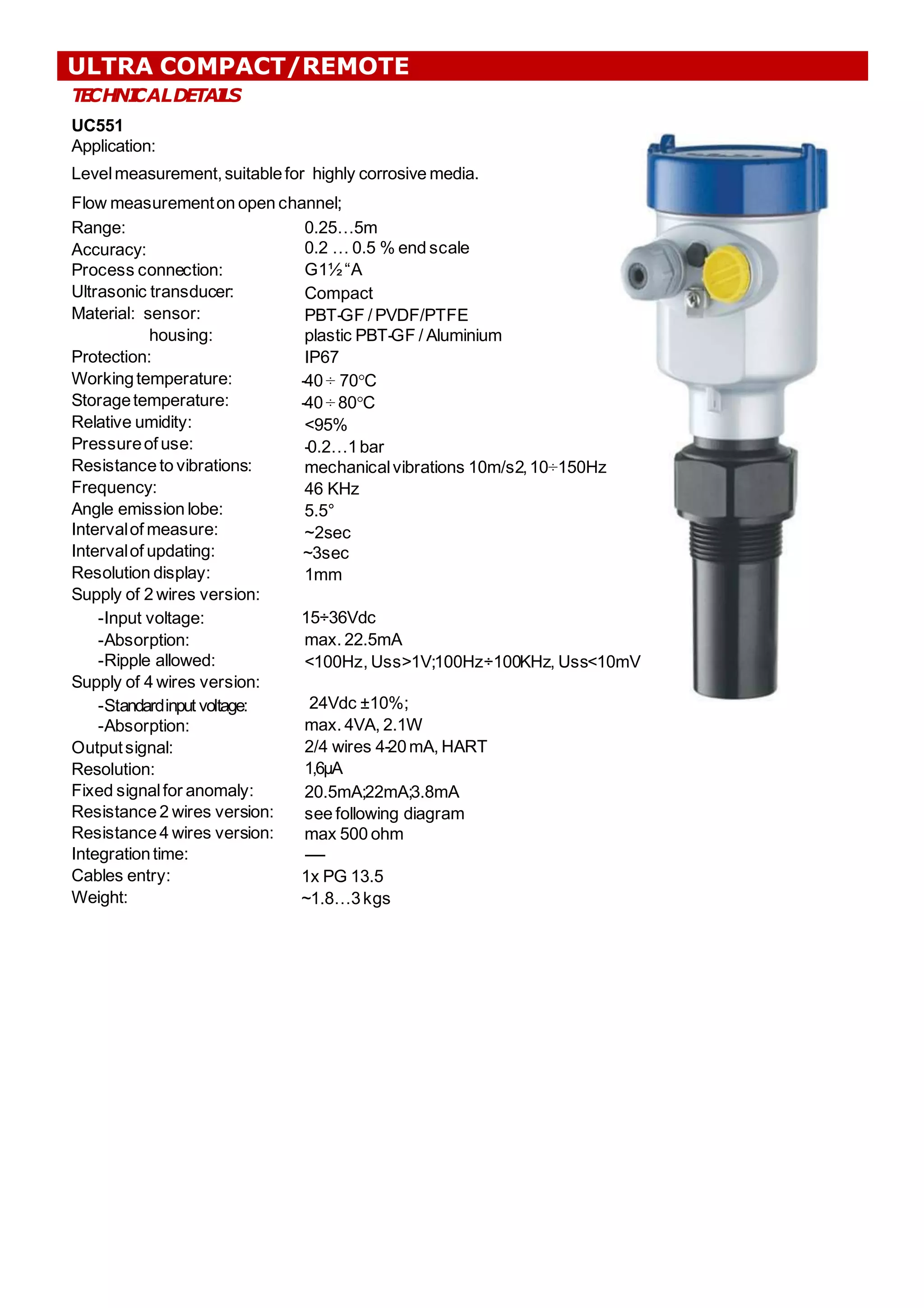
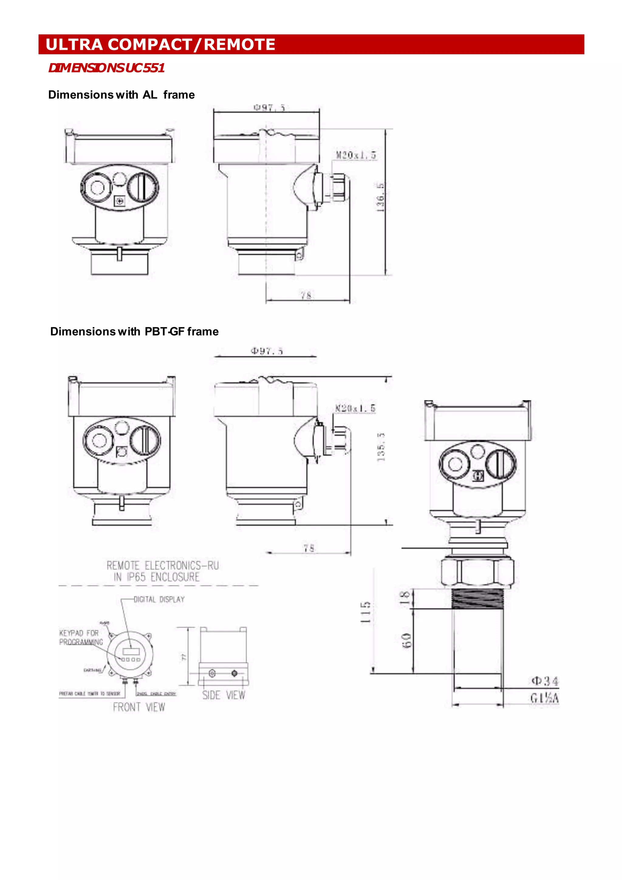
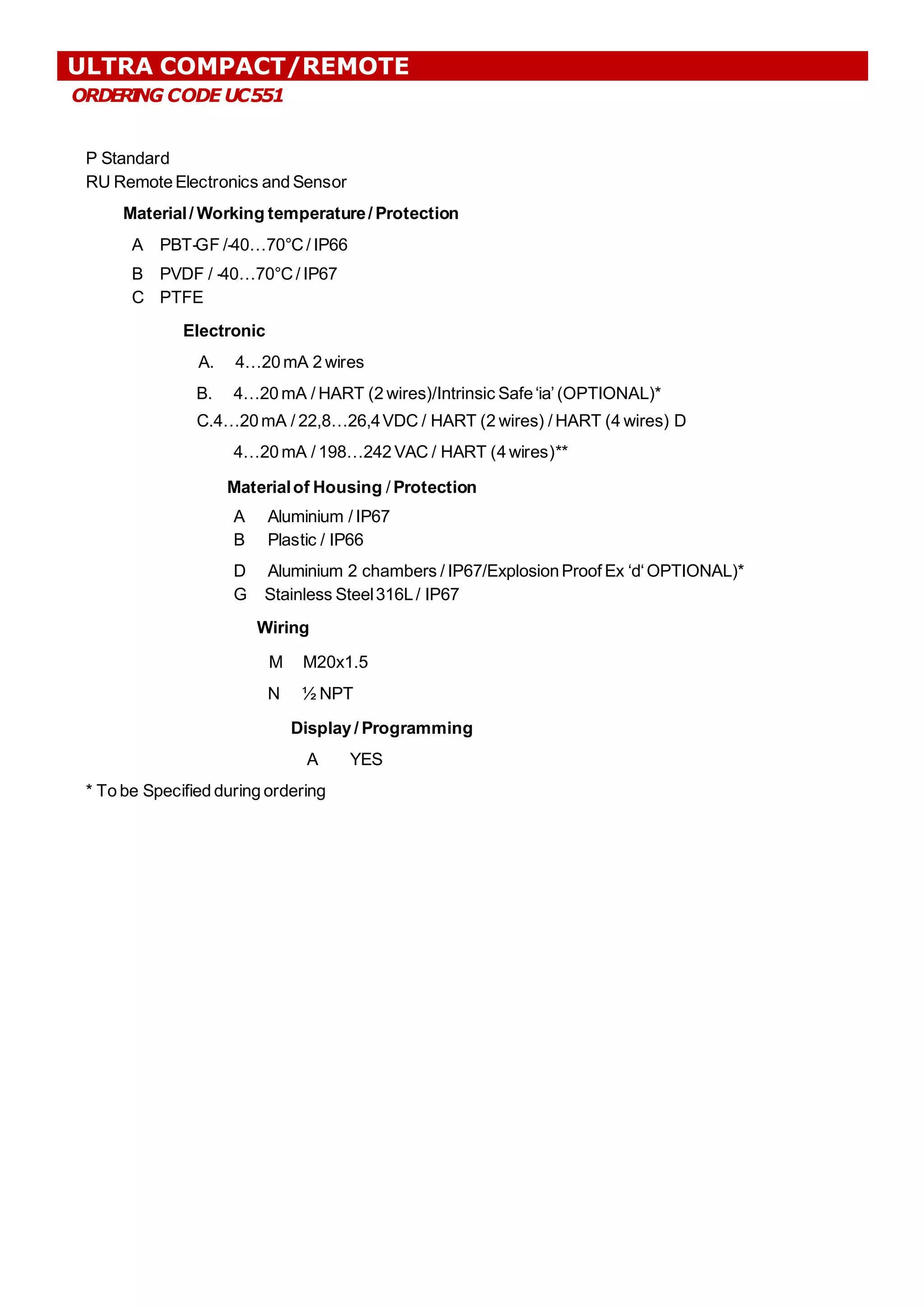
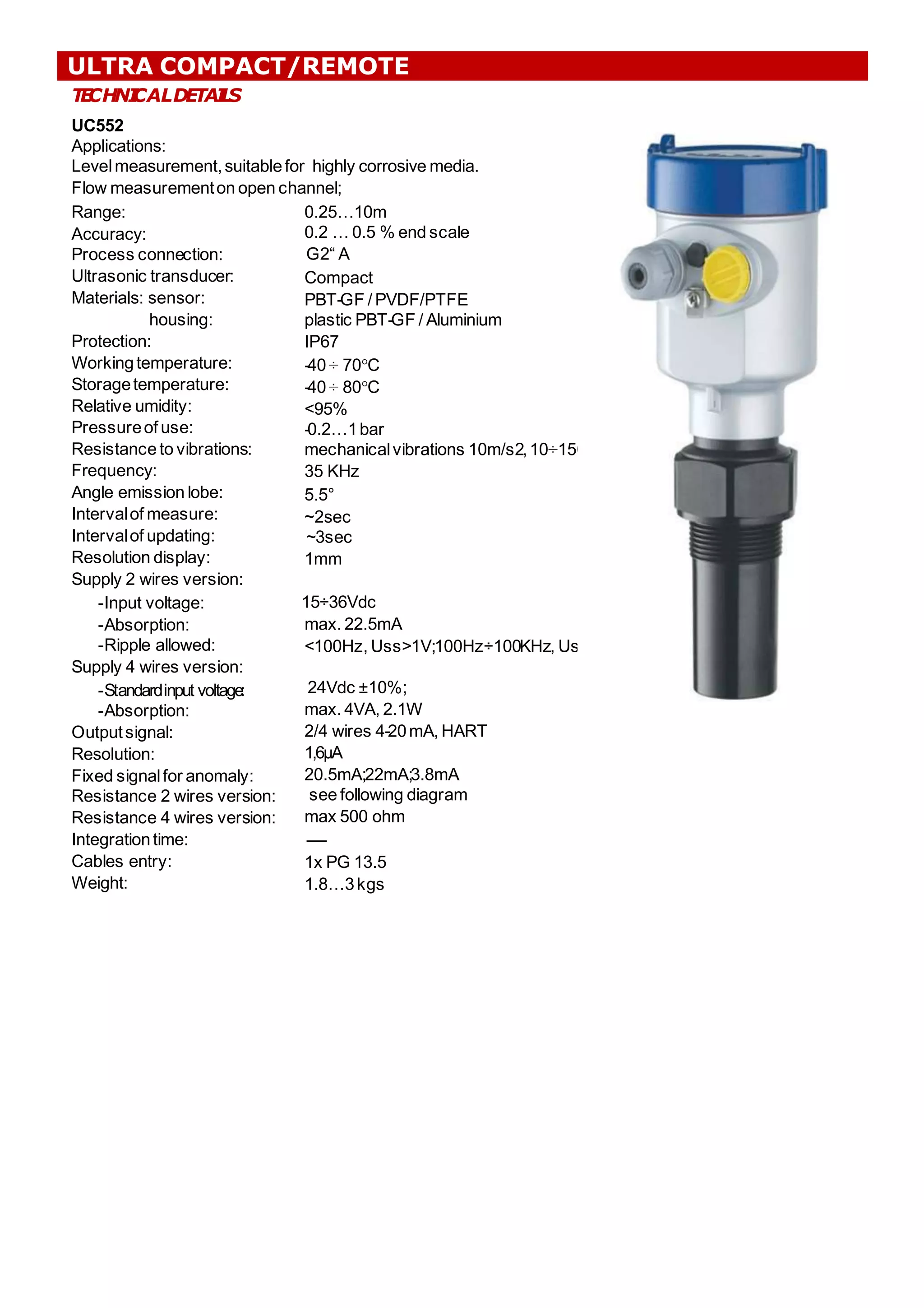
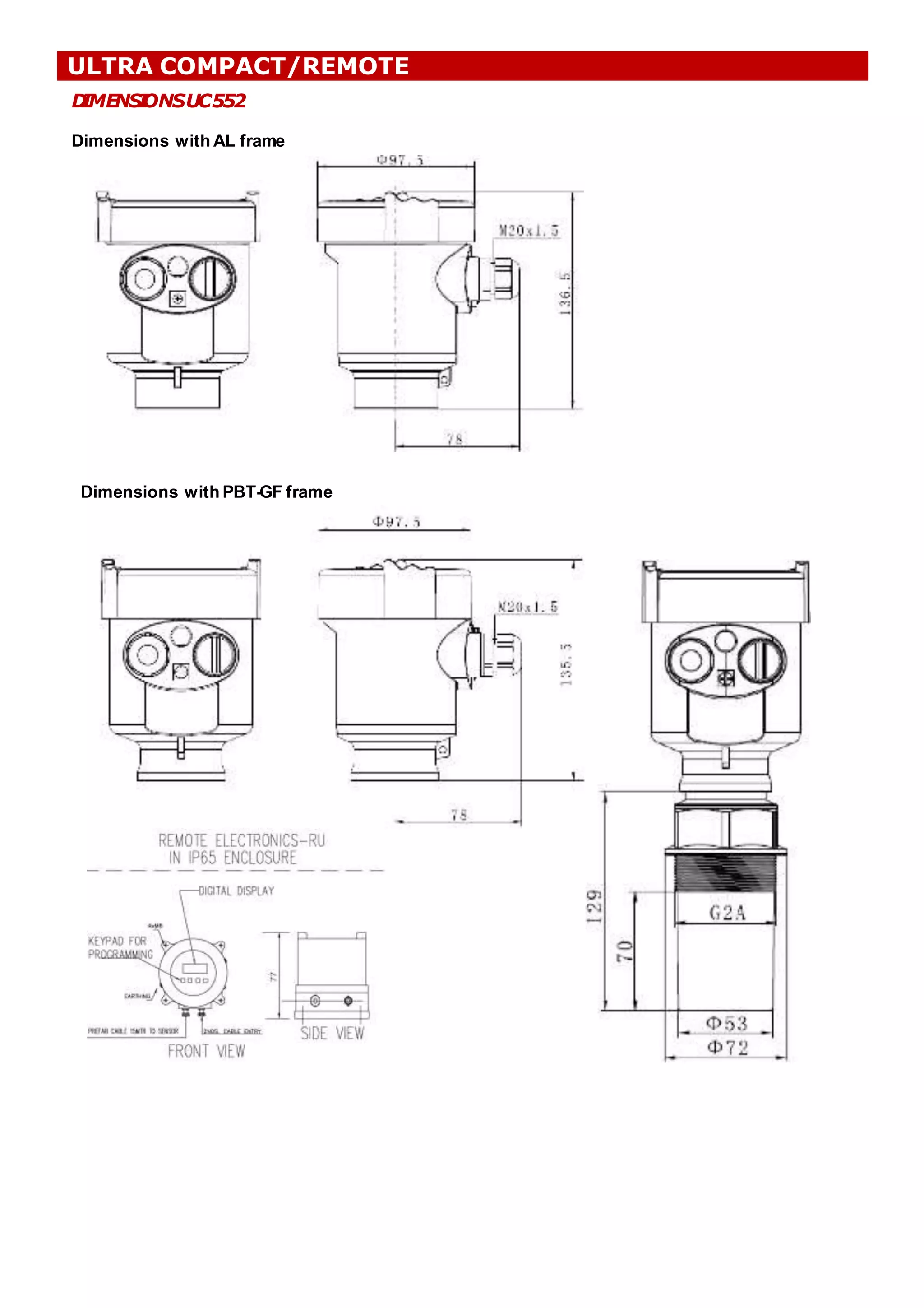
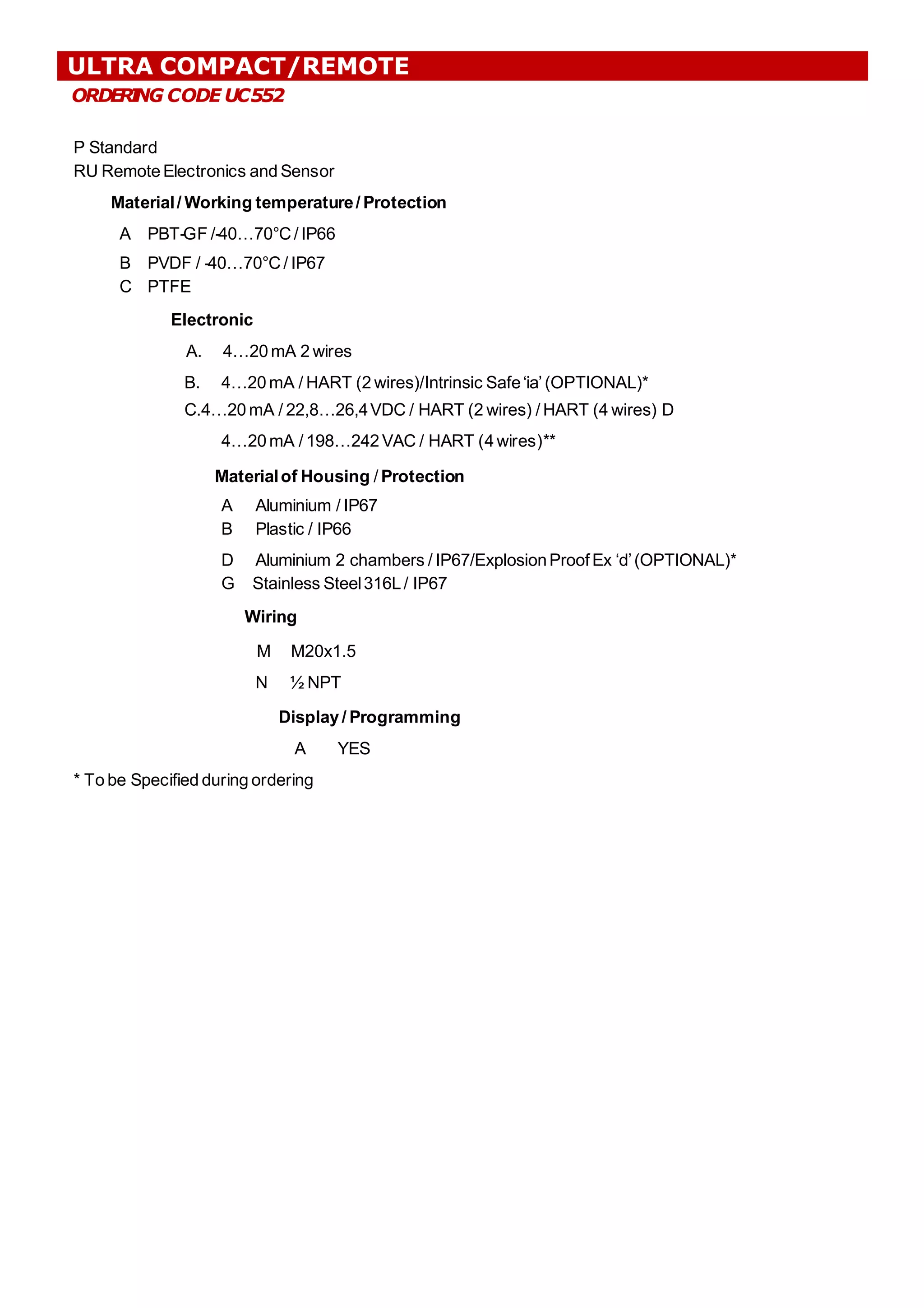
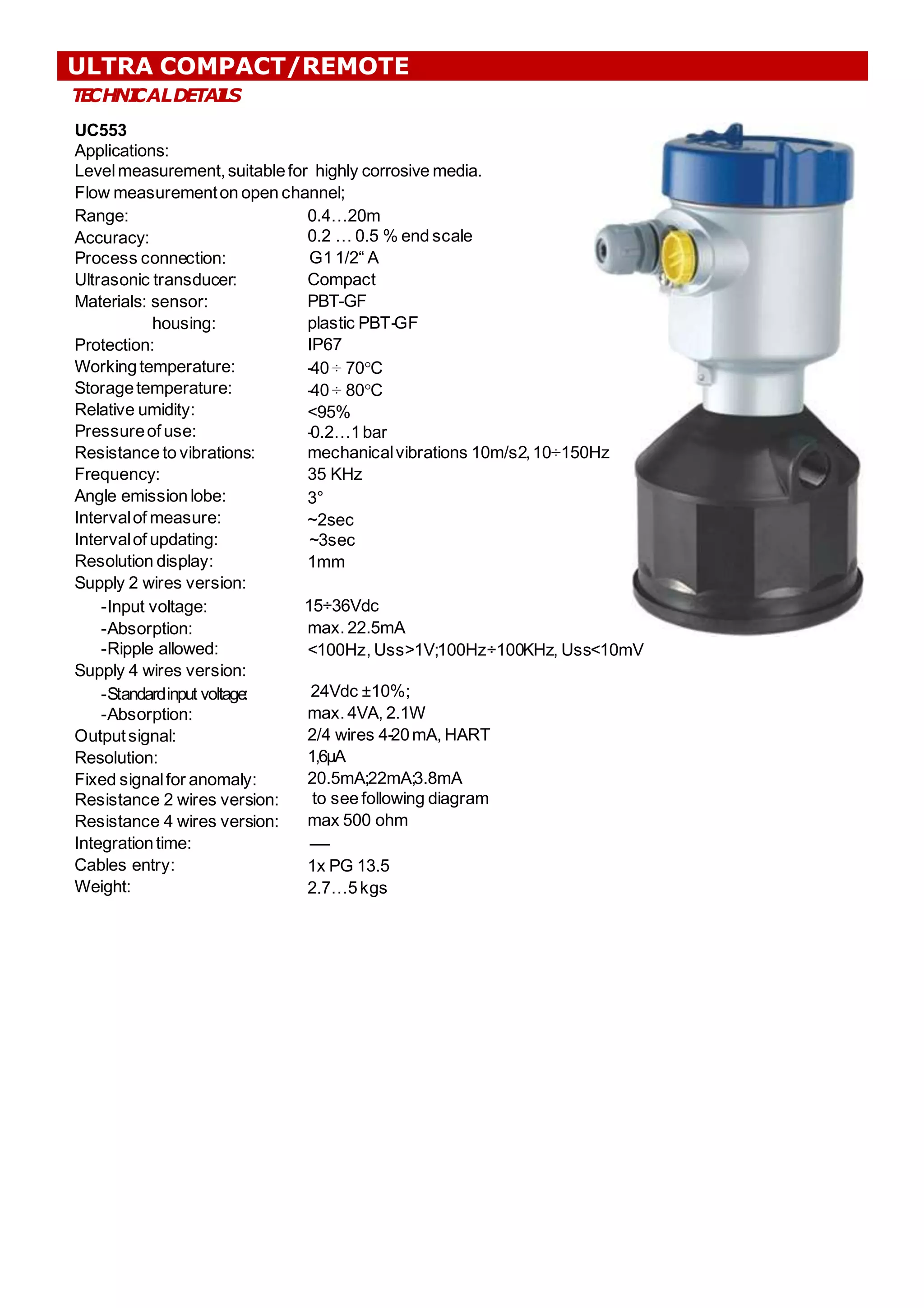
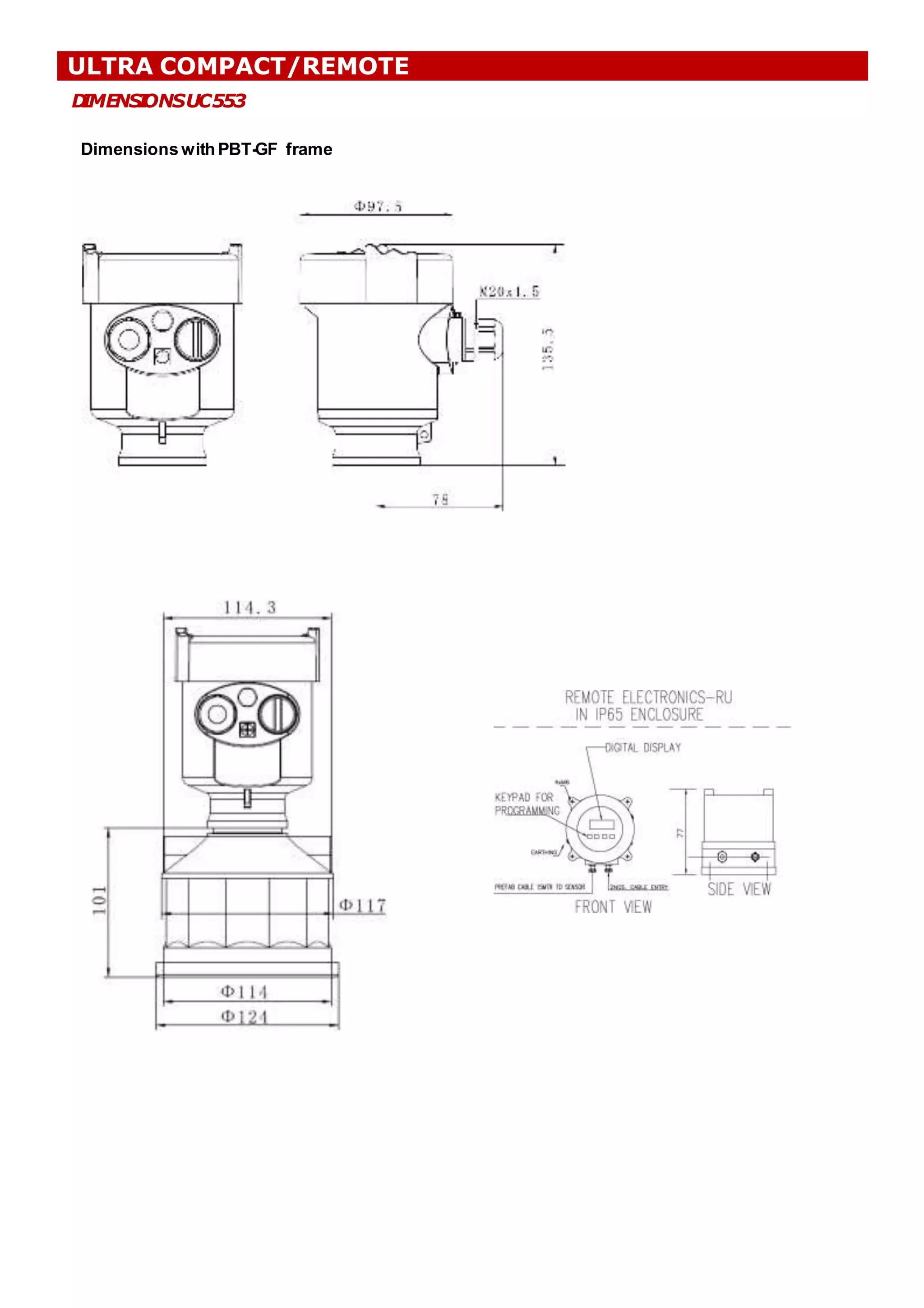
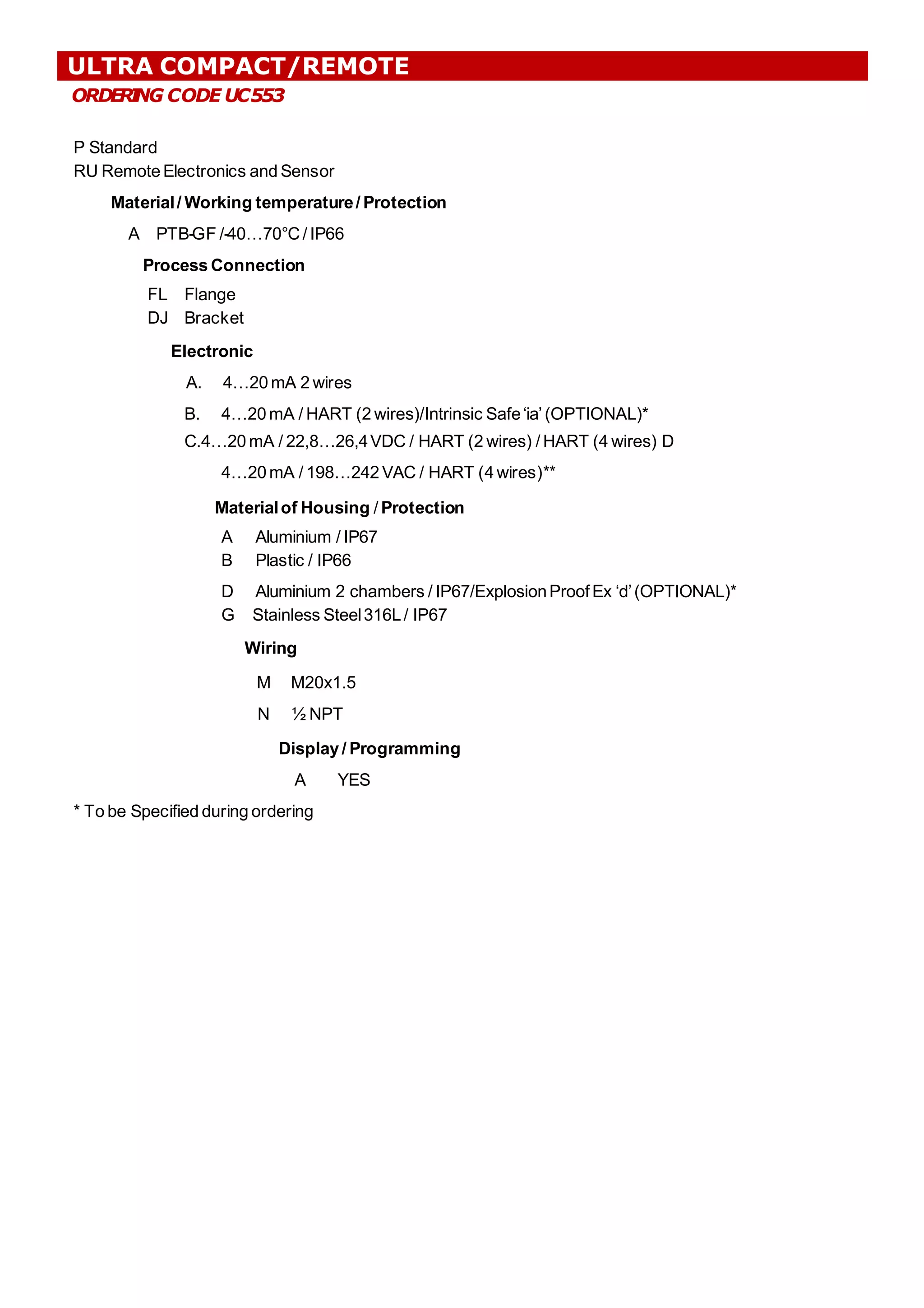
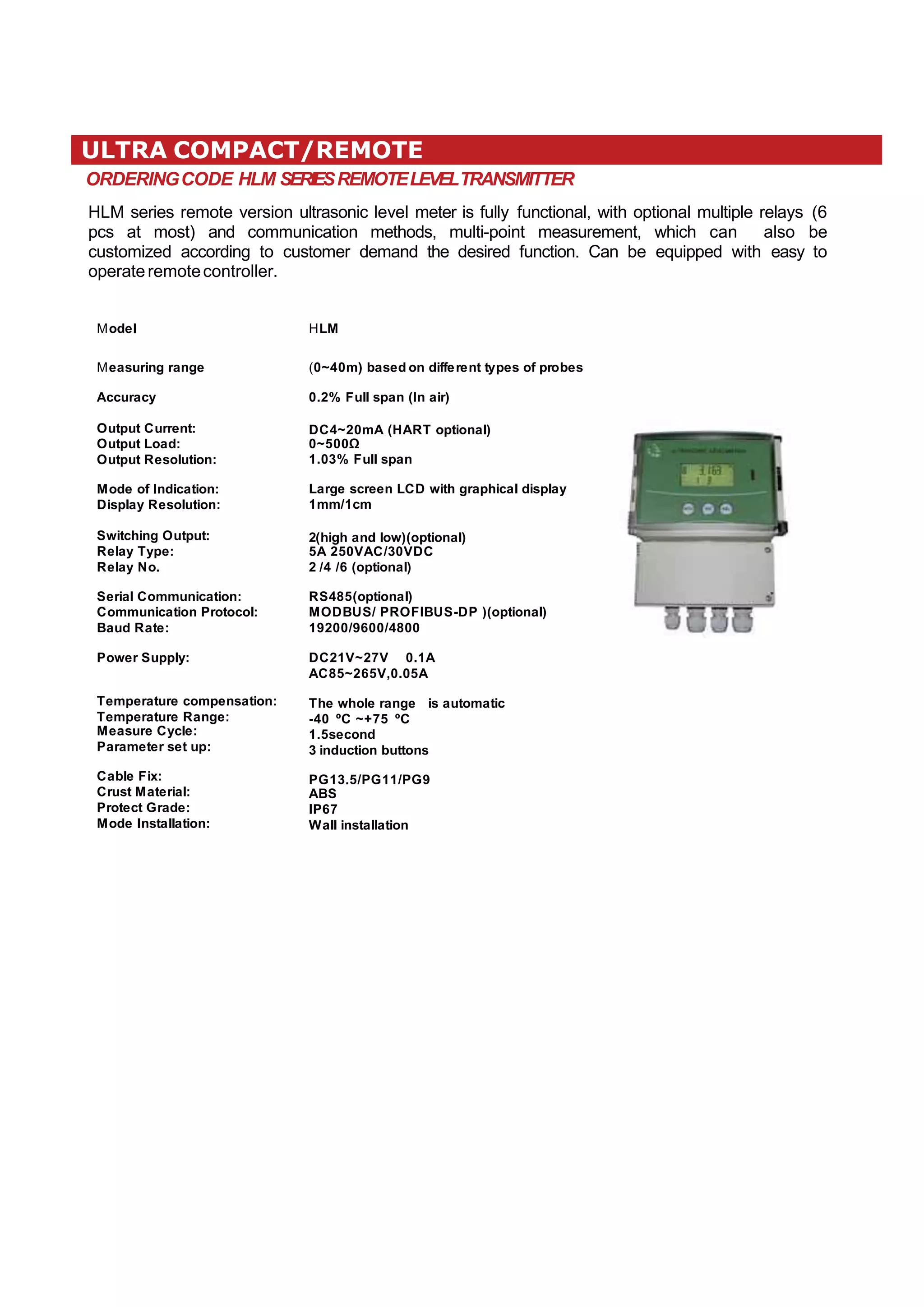
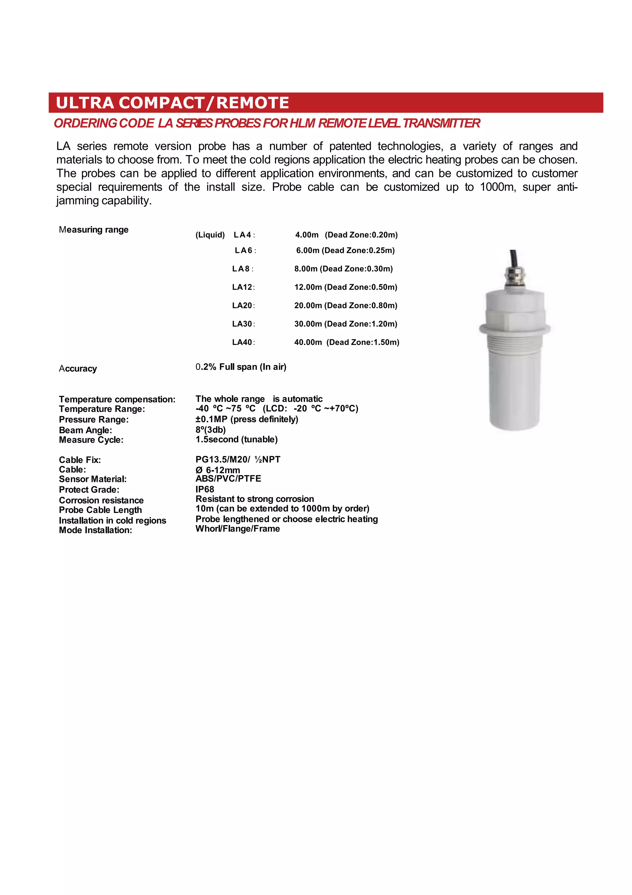
1
ULTRA COMPACT/REMOTE – UC SERIES
ULTRASONIC LEVELINSTRUMENTS
(Compact/Remote version)
DESCRIPTION
The ultrasonic impulses generatedfromtransducers“antennasystem”,which travel
at the speed of sound, come reflected by the surface of medium and newly sent
back to thetransducer.
Theperiod of time that passes betweentheemission of impulses and thereception
of the same ones fromthe antenna,is proportionalto the existingdistancebetween
the same antenna and the higher level of the medium to measure, therefore the
principleof the ultrasonic measure can be illustratedwith the following equation:
S=CXT/2,where S: distance,C: velocity of sound,T: timelapse
Because of the wideband impulses, the overlap between the emission and the reception of the same
impulses increasesin particular zones,extending itself fromthe transducerto the bottom,causing a wrong
measurementof the level. This error zone is defined “blanking zones”and its dimensionvarybased on the
various models of ultrasonic metersthatare used.
The use of an advanced microprocessorand the technology “EchoDiscovery”, allows the user of the
instrument also in criticalzones with heavy jobs.The function“Falseecho storage”assuresthe device to
identify the correct echoalso in presence of false ECHO, supplying correct measures. The integrated
temperaturesensor puts into effecta temperaturecompensation in realtime.
P
R
ODUCT
SOVER
W
I
EV–TECH
NI
CALDET
AI
L
S
UC551 UC552 UC553
DISPLAY
The instruments can be set up
in 3 ways:
1. by display
2. by BMware software
3. by HART program
.
NOTE: Pictures are showing Aluminium Housings
REMOTE UNIT – RU
T
E
CHNI
CALDETAI
L
S
UC551
Application:
Levelmeasurement,suitablefor highly corrosive media.
Flow measurementon open channel;
;
0.25…5m
0.2 … 0.5 % end scale
G1½“A
Compact
PBT-GF / PVDF/PTFE
plastic PBT-GF / Aluminium
IP67
-40 ÷ 70°C
-40 ÷ 80°C
<95%
-0.2…1bar
mechanicalvibrations 10m/s2,10÷150Hz
46 KHz
5.5°
~2sec
~3sec
1mm
Range:
Accuracy:
Process connection:
Ultrasonic transducer:
Material: sensor:
housing:
Protection:
Workingtemperature:
Storagetemperature:
Relative umidity:
Pressureof use:
Resistance to vibrations:
Frequency:
Angle emission lobe:
Intervalof measure:
Intervalof updating:
Resolution display:
Supply of 2 wires version:
-Input voltage:
-Absorption:
-Ripple allowed:
Supply of 4 wires version:
-Standardinput voltage:
-Absorption:
Outputsignal:
Resolution:
Fixed signalfor anomaly:
Resistance 2 wires version:
Resistance 4 wires version:
Integrationtime:
Cables entry:
Weight:
15÷36Vdc
max. 22.5mA
<100Hz, Uss>1V;
;100Hz÷100KHz, Uss<10mV
24Vdc ±10%;
;
max. 4VA, 2.1W
2/4 wires 4-20mA, HART
1,6μA
20.5mA;
;22mA;
;3.8mA
see following diagram
max 500 ohm
------
1x PG 13.5
~1.8…3kgs
ULTRA COMPACT/REMOTE
D
IMENS
I
ONSUC551
Dimensions with AL frame
Dimensionswith PBT-GF frame
ULTRA COMPACT/REMOTE
ORDER
I
NG CODE UC551
P Standard
RU RemoteElectronics and Sensor
Material/ Working temperature/ Protection
A PBT-GF /-40…70°C/ IP66
B PVDF / -40…70°C/ IP67
C PTFE
Electronic
A. 4…20 mA 2 wires
B. 4…20 mA / HART (2 wires)/Intrinsic Safe‘ia’(OPTIONAL)*
C.4…20mA / 22,8…26,4VDC / HART (2 wires) / HART (4 wires) D
4…20 mA / 198…242 VAC / HART (4 wires)**
Materialof Housing / Protection
A Aluminium / IP67
B Plastic / IP66
D Aluminium 2 chambers / IP67/ExplosionProof Ex ‘d‘OPTIONAL)*
G Stainless Steel316L/ IP67
Wiring
M M20x1.5
N ½ NPT
Display / Programming
A YES
* To be Specified during ordering
ULTRA COMPACT/REMOTE
T
E
CHNI
CALDETAI
L
S
UC552
Applications:
Levelmeasurement,suitablefor highly corrosive media.
Flow measurementon open channel;
;
0.25…10m
0.2 … 0.5 % end scale
G2“ A
Compact
PBT-GF / PVDF/PTFE
plastic PBT-GF / Aluminium
IP67
-40 ÷ 70°C
-40 ÷ 80°C
<95%
-0.2…1bar
mechanicalvibrations 10m/s2,10÷150Hz
35 KHz
5.5°
~2sec
~3sec
1mm
15÷36Vdc
max. 22.5mA
<100Hz, Uss>1V;
;100Hz÷100KHz, Uss<10mV
Range:
Accuracy:
Process connection:
Ultrasonic transducer:
Materials: sensor:
housing:
Protection:
Workingtemperature:
Storagetemperature:
Relative umidity:
Pressureof use:
Resistance to vibrations:
Frequency:
Angle emission lobe:
Intervalof measure:
Intervalof updating:
Resolution display:
Supply 2 wires version:
-Input voltage:
-Absorption:
-Ripple allowed:
Supply 4 wires version:
-Standardinput voltage:
-Absorption:
Outputsignal:
Resolution:
Fixed signalfor anomaly:
Resistance 2 wires version:
Resistance 4 wires version:
Integrationtime:
Cables entry:
Weight:
24Vdc ±10%;
;
max. 4VA, 2.1W
2/4 wires 4-20mA, HART
1,6μA
20.5mA;
;22mA;
;3.8mA
see following diagram
max 500 ohm
------
1x PG 13.5
1.8…3kgs
ULTRA COMPACT/REMOTE
D
IMENS
I
ONSUC552
Dimensions with AL frame
ULTRA COMPACT/REMOTE
Dimensions with PBT-GF frame
ORDER
I
NG CODE UC552
P Standard
RU Remote Electronics and Sensor
Material/ Working temperature/ Protection
A PBT-GF /-40…70°C/ IP66
B PVDF / -40…70°C/ IP67
C PTFE
Electronic
A. 4…20 mA 2 wires
B. 4…20 mA / HART (2 wires)/Intrinsic Safe‘ia’(OPTIONAL)*
C.4…20 mA / 22,8…26,4VDC / HART (2 wires) / HART (4 wires) D
4…20 mA / 198…242 VAC / HART (4 wires)**
Materialof Housing / Protection
A Aluminium / IP67
B Plastic / IP66
D Aluminium 2 chambers / IP67/ExplosionProofEx ‘d’(OPTIONAL)*
G Stainless Steel316L/ IP67
Wiring
M M20x1.5
N ½ NPT
Display / Programming
A YES
* To be Specified during ordering
ULTRA COMPACT/REMOTE
T
E
CHNI
CALDETAI
L
S
UC553
Applications:
Levelmeasurement,suitablefor highly corrosive media.
Flow measurementon open channel;
;
0.4…20m
0.2 … 0.5 % end scale
G1 1/2“ A
Compact
PBT-GF
plastic PBT-GF
IP67
-40 ÷ 70°C
-40 ÷ 80°C
<95%
-0.2…1bar
mechanicalvibrations 10m/s2,10÷150Hz
35 KHz
3°
~2sec
~3sec
1mm
15÷36Vdc
max. 22.5mA
<100Hz, Uss>1V;
;100Hz÷100KHz, Uss<10mV
Range:
Accuracy:
Process connection:
Ultrasonic transducer:
Materials: sensor:
housing:
Protection:
Workingtemperature:
Storagetemperature:
Relative umidity:
Pressureof use:
Resistance to vibrations:
Frequency:
Angle emission lobe:
Intervalof measure:
Intervalof updating:
Resolution display:
Supply 2 wires version:
-Input voltage:
-Absorption:
-Ripple allowed:
Supply 4 wires version:
-Standardinput voltage:
-Absorption:
Outputsignal:
Resolution:
Fixed signalfor anomaly:
Resistance 2 wires version:
Resistance 4 wires version:
Integrationtime:
Cables entry:
Weight:
24Vdc ±10%;
;
max. 4VA, 2.1W
2/4 wires 4-20mA, HART
1,6μA
20.5mA;
;22mA;
;3.8mA
to see following diagram
max 500 ohm
------
1x PG 13.5
2.7…5kgs
ULTRA COMPACT/REMOTE
D
IMENS
I
ONSUC553
Dimensions with PBT-GF frame
ULTRA COMPACT/REMOTE
ORDER
I
NG CODE UC553
P Standard
RU Remote Electronics and Sensor
Material/ Working temperature/ Protection
A PTB-GF /-40…70°C/ IP66
Process Connection
FL Flange
DJ Bracket
Electronic
A. 4…20 mA 2 wires
B. 4…20 mA / HART (2 wires)/Intrinsic Safe‘ia’(OPTIONAL)*
C.4…20 mA / 22,8…26,4VDC / HART (2 wires) / HART (4 wires) D
4…20mA / 198…242VAC / HART (4wires)**
Materialof Housing / Protection
A Aluminium / IP67
B Plastic / IP66
D Aluminium 2 chambers / IP67/ExplosionProofEx ‘d’(OPTIONAL)*
G Stainless Steel316L/ IP67
Wiring
M M20x1.5
N ½ NPT
Display / Programming
A YES
* To be Specified during ordering
ULTRA COMPACT/REMOTE
ORDERINGCODE HLM SERIESREMOTELEVELTRANSMITTER
HLM series remote version ultrasonic level meter is fully functional, with optional multiple relays (6
pcs at most) and communication methods, multi-point measurement, which can also be
customized according to customer demand the desired function. Can be equipped with easy to
operateremotecontroller.
ModeI HLM
Measuring range
Accuracy
Output Current:
Output Load:
Output ResoIution:
Mode of lndication:
DispIay ResoIution:
Switching Output:
ReIay Type:
ReIay No.
SeriaI Communication:
Communication ProtocoI:
Baud Rate:
Power SuppIy:
Temperature compensation:
Temperature Range:
Measure CycIe:
Parameter set up:
CabIe Fix:
Crust MateriaI:
Protect Grade:
Mode lnstaIIation:
(0~40m) based on different types of probes
0.2% FuII span (ln air)
DC4~20mA (HART optionaI)
0~500Ω
1.03% FuII span
Large screen LCD with graphicaI dispIay
1mm/1cm
2(high and Iow)(optionaI)
5A 250VAC/30VDC
2 /4 /6 (optionaI)
RS485(optionaI)
MODBUS/ PROFlBUS-DP )(optionaI)
19200/9600/4800
DC21V~27V 0.1A
AC85~265V,0.05A
The whoIe range is automatic
-40 ºC ~+75 ºC
1.5second
3 induction buttons
PG13.5/PG11/PG9
ABS
lP67
WaII instaIIation
ULTRA COMPACT/REMOTE
ORDERINGCODE LASERIESPROBESFORHLM REMOTELEVELTRANSMITTER
LA series remote version probe has a number of patented technologies, a variety of ranges and
materials to choose from. To meet the cold regions application the electric heating probes can be chosen.
The probes can be applied to different application environments, and can be customized to customer
special requirements of the install size. Probe cable can be customized up to 1000m, super anti-
jamming capability.
Measuring range
(Liquid) LA4:
LA6:
LA8:
LA12:
LA20:
LA30:
LA40:
0.2% Full span (ln air)
4.00m (Dead Zone:0.20m)
6.00m (Dead Zone:0.25m)
8.00m (Dead Zone:0.30m)
12.00m (Dead Zone:0.50m)
20.00m (Dead Zone:0.80m)
30.00m (Dead Zone:1.20m)
40.00m (Dead Zone:1.50m)
Accuracy
Temperature compensation:
Temperature Range:
Pressure Range:
Beam Angle:
Measure Cycle:
Cable Fix:
Cable:
Sensor Material:
Protect Grade:
Corrosion resistance
Probe Cable Length
lnstallation in cold regions
Mode lnstallation:
The whole range is automatic
-40 ºC ~75 ºC (LCD: -20 ºC ~+70ºC)
±0.1MP (press definitely)
8º(3db)
1.5second (tunable)
PG13.5/M20/ ½NPT
Ø 6-12mm
ABS/PVC/PTFE
lP68
Resistant to strong corrosion
10m (can be extended to 1000m by order)
Probe lengthened or choose electric heating
Whorl/Flange/Frame
12
, rajat@eipenviroindia.com

Ultrasonic Level Transmitter

  • 1.
  • 2.
    ULTRA COMPACT/REMOTE –UC SERIES ULTRASONIC LEVELINSTRUMENTS (Compact/Remote version) DESCRIPTION The ultrasonic impulses generatedfromtransducers“antennasystem”,which travel at the speed of sound, come reflected by the surface of medium and newly sent back to thetransducer. Theperiod of time that passes betweentheemission of impulses and thereception of the same ones fromthe antenna,is proportionalto the existingdistancebetween the same antenna and the higher level of the medium to measure, therefore the principleof the ultrasonic measure can be illustratedwith the following equation: S=CXT/2,where S: distance,C: velocity of sound,T: timelapse Because of the wideband impulses, the overlap between the emission and the reception of the same impulses increasesin particular zones,extending itself fromthe transducerto the bottom,causing a wrong measurementof the level. This error zone is defined “blanking zones”and its dimensionvarybased on the various models of ultrasonic metersthatare used. The use of an advanced microprocessorand the technology “EchoDiscovery”, allows the user of the instrument also in criticalzones with heavy jobs.The function“Falseecho storage”assuresthe device to identify the correct echoalso in presence of false ECHO, supplying correct measures. The integrated temperaturesensor puts into effecta temperaturecompensation in realtime. P R ODUCT SOVER W I EV–TECH NI CALDET AI L S UC551 UC552 UC553 DISPLAY The instruments can be set up in 3 ways: 1. by display 2. by BMware software 3. by HART program . NOTE: Pictures are showing Aluminium Housings REMOTE UNIT – RU
  • 3.
    T E CHNI CALDETAI L S UC551 Application: Levelmeasurement,suitablefor highly corrosivemedia. Flow measurementon open channel; ; 0.25…5m 0.2 … 0.5 % end scale G1½“A Compact PBT-GF / PVDF/PTFE plastic PBT-GF / Aluminium IP67 -40 ÷ 70°C -40 ÷ 80°C <95% -0.2…1bar mechanicalvibrations 10m/s2,10÷150Hz 46 KHz 5.5° ~2sec ~3sec 1mm Range: Accuracy: Process connection: Ultrasonic transducer: Material: sensor: housing: Protection: Workingtemperature: Storagetemperature: Relative umidity: Pressureof use: Resistance to vibrations: Frequency: Angle emission lobe: Intervalof measure: Intervalof updating: Resolution display: Supply of 2 wires version: -Input voltage: -Absorption: -Ripple allowed: Supply of 4 wires version: -Standardinput voltage: -Absorption: Outputsignal: Resolution: Fixed signalfor anomaly: Resistance 2 wires version: Resistance 4 wires version: Integrationtime: Cables entry: Weight: 15÷36Vdc max. 22.5mA <100Hz, Uss>1V; ;100Hz÷100KHz, Uss<10mV 24Vdc ±10%; ; max. 4VA, 2.1W 2/4 wires 4-20mA, HART 1,6μA 20.5mA; ;22mA; ;3.8mA see following diagram max 500 ohm ------ 1x PG 13.5 ~1.8…3kgs ULTRA COMPACT/REMOTE
  • 4.
    D IMENS I ONSUC551 Dimensions with ALframe Dimensionswith PBT-GF frame ULTRA COMPACT/REMOTE
  • 5.
    ORDER I NG CODE UC551 PStandard RU RemoteElectronics and Sensor Material/ Working temperature/ Protection A PBT-GF /-40…70°C/ IP66 B PVDF / -40…70°C/ IP67 C PTFE Electronic A. 4…20 mA 2 wires B. 4…20 mA / HART (2 wires)/Intrinsic Safe‘ia’(OPTIONAL)* C.4…20mA / 22,8…26,4VDC / HART (2 wires) / HART (4 wires) D 4…20 mA / 198…242 VAC / HART (4 wires)** Materialof Housing / Protection A Aluminium / IP67 B Plastic / IP66 D Aluminium 2 chambers / IP67/ExplosionProof Ex ‘d‘OPTIONAL)* G Stainless Steel316L/ IP67 Wiring M M20x1.5 N ½ NPT Display / Programming A YES * To be Specified during ordering ULTRA COMPACT/REMOTE
  • 6.
    T E CHNI CALDETAI L S UC552 Applications: Levelmeasurement,suitablefor highly corrosivemedia. Flow measurementon open channel; ; 0.25…10m 0.2 … 0.5 % end scale G2“ A Compact PBT-GF / PVDF/PTFE plastic PBT-GF / Aluminium IP67 -40 ÷ 70°C -40 ÷ 80°C <95% -0.2…1bar mechanicalvibrations 10m/s2,10÷150Hz 35 KHz 5.5° ~2sec ~3sec 1mm 15÷36Vdc max. 22.5mA <100Hz, Uss>1V; ;100Hz÷100KHz, Uss<10mV Range: Accuracy: Process connection: Ultrasonic transducer: Materials: sensor: housing: Protection: Workingtemperature: Storagetemperature: Relative umidity: Pressureof use: Resistance to vibrations: Frequency: Angle emission lobe: Intervalof measure: Intervalof updating: Resolution display: Supply 2 wires version: -Input voltage: -Absorption: -Ripple allowed: Supply 4 wires version: -Standardinput voltage: -Absorption: Outputsignal: Resolution: Fixed signalfor anomaly: Resistance 2 wires version: Resistance 4 wires version: Integrationtime: Cables entry: Weight: 24Vdc ±10%; ; max. 4VA, 2.1W 2/4 wires 4-20mA, HART 1,6μA 20.5mA; ;22mA; ;3.8mA see following diagram max 500 ohm ------ 1x PG 13.5 1.8…3kgs ULTRA COMPACT/REMOTE
  • 7.
    D IMENS I ONSUC552 Dimensions with ALframe ULTRA COMPACT/REMOTE Dimensions with PBT-GF frame
  • 8.
    ORDER I NG CODE UC552 PStandard RU Remote Electronics and Sensor Material/ Working temperature/ Protection A PBT-GF /-40…70°C/ IP66 B PVDF / -40…70°C/ IP67 C PTFE Electronic A. 4…20 mA 2 wires B. 4…20 mA / HART (2 wires)/Intrinsic Safe‘ia’(OPTIONAL)* C.4…20 mA / 22,8…26,4VDC / HART (2 wires) / HART (4 wires) D 4…20 mA / 198…242 VAC / HART (4 wires)** Materialof Housing / Protection A Aluminium / IP67 B Plastic / IP66 D Aluminium 2 chambers / IP67/ExplosionProofEx ‘d’(OPTIONAL)* G Stainless Steel316L/ IP67 Wiring M M20x1.5 N ½ NPT Display / Programming A YES * To be Specified during ordering ULTRA COMPACT/REMOTE
  • 9.
    T E CHNI CALDETAI L S UC553 Applications: Levelmeasurement,suitablefor highly corrosivemedia. Flow measurementon open channel; ; 0.4…20m 0.2 … 0.5 % end scale G1 1/2“ A Compact PBT-GF plastic PBT-GF IP67 -40 ÷ 70°C -40 ÷ 80°C <95% -0.2…1bar mechanicalvibrations 10m/s2,10÷150Hz 35 KHz 3° ~2sec ~3sec 1mm 15÷36Vdc max. 22.5mA <100Hz, Uss>1V; ;100Hz÷100KHz, Uss<10mV Range: Accuracy: Process connection: Ultrasonic transducer: Materials: sensor: housing: Protection: Workingtemperature: Storagetemperature: Relative umidity: Pressureof use: Resistance to vibrations: Frequency: Angle emission lobe: Intervalof measure: Intervalof updating: Resolution display: Supply 2 wires version: -Input voltage: -Absorption: -Ripple allowed: Supply 4 wires version: -Standardinput voltage: -Absorption: Outputsignal: Resolution: Fixed signalfor anomaly: Resistance 2 wires version: Resistance 4 wires version: Integrationtime: Cables entry: Weight: 24Vdc ±10%; ; max. 4VA, 2.1W 2/4 wires 4-20mA, HART 1,6μA 20.5mA; ;22mA; ;3.8mA to see following diagram max 500 ohm ------ 1x PG 13.5 2.7…5kgs ULTRA COMPACT/REMOTE
  • 10.
  • 11.
    ORDER I NG CODE UC553 PStandard RU Remote Electronics and Sensor Material/ Working temperature/ Protection A PTB-GF /-40…70°C/ IP66 Process Connection FL Flange DJ Bracket Electronic A. 4…20 mA 2 wires B. 4…20 mA / HART (2 wires)/Intrinsic Safe‘ia’(OPTIONAL)* C.4…20 mA / 22,8…26,4VDC / HART (2 wires) / HART (4 wires) D 4…20mA / 198…242VAC / HART (4wires)** Materialof Housing / Protection A Aluminium / IP67 B Plastic / IP66 D Aluminium 2 chambers / IP67/ExplosionProofEx ‘d’(OPTIONAL)* G Stainless Steel316L/ IP67 Wiring M M20x1.5 N ½ NPT Display / Programming A YES * To be Specified during ordering ULTRA COMPACT/REMOTE
  • 12.
    ULTRA COMPACT/REMOTE ORDERINGCODE HLMSERIESREMOTELEVELTRANSMITTER HLM series remote version ultrasonic level meter is fully functional, with optional multiple relays (6 pcs at most) and communication methods, multi-point measurement, which can also be customized according to customer demand the desired function. Can be equipped with easy to operateremotecontroller. ModeI HLM Measuring range Accuracy Output Current: Output Load: Output ResoIution: Mode of lndication: DispIay ResoIution: Switching Output: ReIay Type: ReIay No. SeriaI Communication: Communication ProtocoI: Baud Rate: Power SuppIy: Temperature compensation: Temperature Range: Measure CycIe: Parameter set up: CabIe Fix: Crust MateriaI: Protect Grade: Mode lnstaIIation: (0~40m) based on different types of probes 0.2% FuII span (ln air) DC4~20mA (HART optionaI) 0~500Ω 1.03% FuII span Large screen LCD with graphicaI dispIay 1mm/1cm 2(high and Iow)(optionaI) 5A 250VAC/30VDC 2 /4 /6 (optionaI) RS485(optionaI) MODBUS/ PROFlBUS-DP )(optionaI) 19200/9600/4800 DC21V~27V 0.1A AC85~265V,0.05A The whoIe range is automatic -40 ºC ~+75 ºC 1.5second 3 induction buttons PG13.5/PG11/PG9 ABS lP67 WaII instaIIation
  • 13.
    ULTRA COMPACT/REMOTE ORDERINGCODE LASERIESPROBESFORHLMREMOTELEVELTRANSMITTER LA series remote version probe has a number of patented technologies, a variety of ranges and materials to choose from. To meet the cold regions application the electric heating probes can be chosen. The probes can be applied to different application environments, and can be customized to customer special requirements of the install size. Probe cable can be customized up to 1000m, super anti- jamming capability. Measuring range (Liquid) LA4: LA6: LA8: LA12: LA20: LA30: LA40: 0.2% Full span (ln air) 4.00m (Dead Zone:0.20m) 6.00m (Dead Zone:0.25m) 8.00m (Dead Zone:0.30m) 12.00m (Dead Zone:0.50m) 20.00m (Dead Zone:0.80m) 30.00m (Dead Zone:1.20m) 40.00m (Dead Zone:1.50m) Accuracy Temperature compensation: Temperature Range: Pressure Range: Beam Angle: Measure Cycle: Cable Fix: Cable: Sensor Material: Protect Grade: Corrosion resistance Probe Cable Length lnstallation in cold regions Mode lnstallation: The whole range is automatic -40 ºC ~75 ºC (LCD: -20 ºC ~+70ºC) ±0.1MP (press definitely) 8º(3db) 1.5second (tunable) PG13.5/M20/ ½NPT Ø 6-12mm ABS/PVC/PTFE lP68 Resistant to strong corrosion 10m (can be extended to 1000m by order) Probe lengthened or choose electric heating Whorl/Flange/Frame
  • 14.