SlideShare a Scribd company logo
Siemens LV 30 · 20044/2
Molded-Case Circuit-Breakers (MCCB)
Introduction
4
■Overview
✓ available
– not available
Type VL160X VL160 VL250 VL400 VL630 VL800
SENTRON VL molded-case circuit-breakers up to 1600 A
Rated current In
at 50 °C ambient temperature
A 16 ... 160 A 25 ... 160 A 80 ... 250 A 126 ... 400 A 252 ... 630 A 320 ... 800 A
Number of poles 3 4 3 4 3 4 3 4 3 4 3 4
Rated operating voltage Ue
AC 50/60 Hz
DC (only with thermal-
magnetic trip unit)
V
V
690
500 500
690
600 750
690
600 750
690
600 750
690
600 750
690
– –
Overcurrent trip units
Thermal-magnetic
Electronic ETU/LCD
Replaceable
PROFIBUS module COM10
✓
–
–
–
✓
–
–
–
✓
✓
✓
✓
✓
✓
✓
✓
✓
✓
✓
✓
✓
✓
✓
✓
✓
✓
✓
✓
✓
✓
✓
✓
✓
✓
✓
✓
✓
✓
✓
✓
–
✓
✓
✓
–
✓
✓
✓
Dimensions
A
B
C
D
mm
mm
mm
mm
105
158
82
107
140
158
82
107
105
175
82
107
140
175
82
107
105
175
82
107
140
175
82
107
139
280
102
139
184
280
102
139
190
280
102
139
254
280
102
139
190
407
115
152
254
407
115
152
Switching capacity Icu/Ics
r.m.s. value, to IEC 60947-2
Standard switching capacity N
up to AC 240 V
up to AC 415 V
up to AC 690 V
kA
kA
kA
65/65
40/40
8/4
65/65
40/40
12/6
65/65
40/40
12/6
65/65
45/45
15/8
65/65
45/45
20/10
65/65
50/50
20/10
up to DC 250 V
up to DC 600 V
up to DC 750 V
kA
kA
kA
30
–
–
30
–
–
30
–
–
30
–
–
30
–
–
–
–
–
High switching capacity H
up to AC 240 V
up to AC 415 V
up to AC 690 V
kA
kA
kA
100/75
70/70
12/6
100/75
70/70
12/6
100/75
70/70
12/6
100/75
70/70
15/8
100/75
70/70
30/15
100/75
70/70
30/15
up to DC 250 V
up to DC 600 V
up to DC 750 V
kA
kA
kA
30
–
–
30
–
–
30
–
–
30
–
–
30
30
–
–
–
–
Very high switching capacity L
up to AC 240 V
up to AC 415 V
up to AC 690 V
kA
kA
kA
–
–
–
150/150
100/75
12/6
200/150
100/75
12/6
200/150
100/75
15/8
200/150
100/75
35/17
200/150
100/75
35/17
up to DC 250 V
up to DC 600 V
up to DC 750 V
kA
kA
kA
–
–
–
30
30
30
30
30
30
30
30
30
30
30
30
–
–
–
NSE0_01159
D
CA
B
Siemens LV 30 · 2004 4/3
Molded-Case Circuit-Breakers (MCCB)
Introduction
4
VL1250 VL1600 3VF2 3VF3 3VF4 3VF5 3VF6 3VF7 3VF8
SENTRON VL molded-case
circuit-breakers up to 1600 A
Molded-case circuit-breakers up to 2500 A
400 ... 1250 A 640 ... 1600 A 16 ... 125 160, 205, 225 220/250 315/400 500/630/800 800/1250 1600/2000, 2500
3 4 3 4 3 and 4 3 and 4 3 and 4 3 and 4 3 and 4 3 and 4 3 and 4
690
–
690
–
up to 415
–
690
750
690
750
690
750
690
750
690
–
690
–
–
✓
✓
✓
–
✓
✓
✓
–
✓
✓
✓
–
✓
✓
✓
✓
–
–
–
✓
✓
–
–
✓
–
–
–
✓
✓
–
–
✓
✓
–
–
✓
✓
–
–
✓
✓
–
–
229
407
153
209
305
407
153
209
229
537
153
209
305
537
153
209
76/102
124
68
73
105/140
153
81
105
105/140
254
97
126
140/183
258
97
126
210/280
273
97
141
210/280
406
140
183
394/508
407
229
305
65/35
50/25
20/10
65/35
50/25
20/10
65/33
18/9
–
85/851
)
40/401
)
12/6
85/85
40/40
14/7
85/85
45/45
20/10
85/852
)
45/452
)
20/102)
85/85
50/50
20/10
–
–
–
–
–
–
–
–
–
–
–
–
20/10
20/10
20/10
20
20
20
20
20
20
20
20
20
–
–
–
–
–
–
75/50
70/35
30/15
100/50
70/35
30/15
–
–
–
100/100
70/70
14/7
100/100
70/70
18/9
100/100
70/70
25/13
100/100
70/70
25/13
100/100
70/50
25/13
135/100
70/50
25/13
–
–
–
–
–
–
–
–
–
20/10
20/10
20/10
20
20
20
20
20
20
20
20
20
–
–
–
–
–
–
200/100
100/50
35/17
200/100
100/50
35/17
–
–
–
200/150
100/75
18/9
200/150
100/75
22/11
200/150
100/75
35/18
200/150
100/75
35/18
200/100
100/50
35/18
200/100
100/50
35/18
–
–
–
–
–
–
–
–
–
20/10
20/10
20/10
20
20
20
20
20
20
20
20
20
–
–
–
–
–
–
1) or up to AC 240 V: 40/40 kA and up to AC 415 V: 25/25 kA.
2) or at In = 800 A; up to AC 240 V: 65/33 kA; up to AC 415 V: 50/25 kA;
up to 690 V: 20/10 kA.
Siemens LV 30 · 20044/4
SENTRON VL Circuit-Breakers up to 1600 A
General data
4
■Overview
$ Withdrawable/plug-in base
% Side walls for withdrawable version
& Phase barriers
( Flared front busbar connecting bars
) Straight connecting bars
* Multiple supply terminal for Al/Cu
+ Box terminal for Cu
, Extended terminal cover
- Standard terminal cover
. Masking frame/cover frame for door cut-out
/ Motorized operating mechanism with spring energy store
0 Front-operated rotary operating mechanism
1 Door-coupling rotary operating mechanism
2 SENTRON VL circuit-breaker
3 Internal accessories
4 Electronic overcurrent trip unit
5 Thermal/magnetic overcurrent trip unit
6 RCD module
7 Rear terminals – flat and round
8 COM10 communication module to the PROFIBUS DP
9 Manual tester for electronic trip unit
.
0
/
1
.
Siemens LV 30 · 2004 4/5
SENTRON VL Circuit-Breakers up to 1600 A
General data
4
-
*
(
,
%&
)
9
$
2
4
3
-
,
&
6
5
( 7
*
8
+
)
+
Siemens LV 30 · 20044/6
SENTRON VL Circuit-Breakers up to 1600 A
General data
4
■Benefits
• The compact design of the SENTRON VL circuit-breakers cou-
pled with excellent characteristics fulfills the high demands of
today's electrical distribution systems.
• These circuit-breakers offer a broad product range, improved
technology, space savings and easy operation.
• They are available both in thermal/magnetic (16 A to 630 A)
and in electronic versions (63 A to 1600 A).
■Area of application
The different versions of SENTRON VL circuit-breakers are suit-
able for the following applications:
• Incoming and outgoing circuit-breakers in distribution systems
• Switching and protection devices for motors, transformers and
capacitors
• Main control switches and EMERGENCY-STOP switches in
conjunction with lockable rotary operating mechanism and ter-
minal covers.
The SENTRON VL circuit-breakers are available in the following
versions:
1. For system protection (in 3 and 4-pole versions)
The overload and short-circuit releases are designed for the pro-
tection of cables, leads and non-motor loads.
2. For motor protection (in 3-pole versions)
The overload and short-circuit releases are designed for opti-
mized protection and direct starting of three-phase squirrel-cage
motors. The circuit-breakers for motor protection are susceptible
to phase failure and feature an adjustable trip class. The over-
current trip units operate with a microprocessor.
3. For starter combinations (in 3-pole versions)
These circuit-breakers are used both for short-circuit protection
as well as for isolating functions, which may be required in
starter combinations consisting of circuit-breakers, overload re-
lays and motor contactors. These circuit-breakers exclusively
feature adjustable, instantaneous short-circuit releases.
4. As non-automatic circuit-breakers (in 3- and 4-pole versions)
These circuit-breakers can be used as feeder circuit-breakers,
main control switches or disconnecting switches without over-
load protection. They incorporate an integrated short-circuit self-
protection system, eliminating the need for back-up fuses.
Standards and specifications
SENTRON VL circuit-breakers comply with:
IEC 60947-1, EN 60947-1,
DIN VDE 0660, Part 100,
IEC 60947-2, EN 60947-2,
DIN VDE 0660, Part 101.
Isolating features to IEC 60947-3, EN 60947-3.
Please contact Siemens for details of other standards.
The overcurrent trip units of the circuit-breakers for motor protec-
tion also fulfill IEC 60947-4-1, DIN VDE 0660, Part 102.
Main control switches to EN 60204 or DIN VDE 0113 (see Area
of application). EMERGENCY-STOP switches to EN 60204 or
DIN VDE 0113 (see Area of application).
Operating conditions
The SENTRON VL circuit-breakers are climate-proof.
They are intended for use in enclosed areas where no severe op-
erating conditions (e.g. dust, corrosive vapors, damaging
gases) are present.
When installed in dusty and damp areas, suitable enclosures
must be provided.
Utilization category
All SENTRON VL circuit-breakers satisfy utilization category A.
Degree of protection
RCD module
The RCD module is designed for retrofitting to the switch. It can
also be retrofitted by the customer.
The combination of SENTRON VL circuit-breaker and RCD
module can be fed from the top or bottom.
All SENTRON VL circuit-breakers with RCD modules are avail-
able with auxiliary switches, alarm switches, undervoltage and
shunt releases.
Protection of plant and equipment against overload or damage
by ground faults (ground fault protection).
The RCD module trips the circuit-breaker through vectorial sum-
mation current formation for all phase currents if the vectorial
sum of the currents in the poles (= the ground fault current) ex-
ceeds the pre-set response and delay time values. AC currents
and pulsating DC currents are measured (CBR, design A to
EN 60947-2).
Circuit-breaker IP20
Masking frame IP40
Terminal covers IP30
With front rotary operating mechanism IP40
With door-coupling rotary mechanism IP65
With motorized operating mechanism IP30
With motorized operating mechanism and
masking frame for the door cut-out
IP40
Plug-in base/withdrawable version IP20
Siemens LV 30 · 2004 4/7
SENTRON VL Circuit-Breakers up to 1600 A
General data
4
Switching of DC currents
The VL160X to VL630 circuit-breakers (for system protection with
TM, for starter combinations, non-automatic circuit-breakers)
can also be used for DC switching and protection applications.
The VL160 to VL1600 circuit-breakers with electronic trip units
(ETU) are not suitable for DC applications.
However, the maximum permitted DC voltage for each current
path needs to be taken into account for DC switching applica-
tions.
For voltages above 250 V, a series connection of 2 or 3 current
paths is required.
As the current has to flow through all of the current paths, the fol-
lowing connections are recommended in order to satisfy the
thermal tripping characteristics.
With DC applications, the response values of the instantaneous
short-circuit releases ("I" trip units) are increased by 30 to 40%.
■Design
• Rated current range from 16 A to 1600 A
• Different switching capacity for each frame size
• No derating or loss of performance up to 50°C
• Electronic overcurrent trip units from size 160 A (VL160), partic-
ularly for time-based discrimination and ground-fault protec-
tion
• 2 families of internal accessories
• Full range of external accessories e.g. terminals for aluminum
cable.
All circuit-breakers are supplied with integrated overcurrent trip
units. The SENTRON VL160X to VL1600 circuit-breakers are avail-
able with busbar connection pieces or box terminals (up to
400 A; see Page 4/10). Auxiliary switches/alarm switches or aux-
iliary releases can be easily adapted by the customer, or they
are also available ready installed if required.
The switching capacity is shown on the front of every circuit-
breaker.
• Standard switching capacity:
Icu = 40 to 50 kA at AC 50/60 Hz 380/415 V
• High switching capacity:
Icu = 70 kA at AC 50/60 Hz 380/415 V
• Very high switching capacity:
Icu = 100 kA at AC 50/60 Hz 380/415 V
Recommended connection Maximum permitted DC voltage Ue Remarks
For 3 and 4-pole circuit-breakers
DC 250 V 2-pole switching (ungrounded system)
If there is no possibility of a ground fault, or if every ground fault is rectified
immediately (ground-fault monitoring), then the maximum permitted DC volt-
age is 600 V.
DC 500 V 2-pole switching (grounded system)
The grounded pole is always assigned to the individual current path, so that
there are always 2 current paths in series in the event of a ground fault.
DC 600 V 1-pole switching (grounded system)
3 current paths in series.
The grounded pole is assigned to the unconnected current path.
DC 750 V 1-pole switching (grounded system)
4 current paths in series.
The grounded pole is assigned to the unconnected current path.
L
NSE0_00741
M
L
L
NSE0_00742
M
L
L
NSE0_00743
M
L
L L
NSE0_00744
M
N Standard (40 to 50 kA)
H High (70 kA)
L Very high (100 kA)
Siemens LV 30 · 20044/8
SENTRON VL Circuit-Breakers up to 1600 A
General data
4
Connection
The SENTRON VL160X to VL160 circuit-breakers are equipped
with incoming and outgoing terminals which are suitable for
stranded conductors, flexible copper rails and conductors with
end sleeves. Different supply terminals are available for VL630
to VL1600 (sizes 630 A to 1600 A).
Appropriate accessories for screw connection to fixed and flex-
ible copper bars or cables are available for SENTRON VL160X
to VL1600 circuit-breakers.
SENTRON VL160X to VL1600 circuit-breakers can be equipped
with connecting bars. These are intended for connection of stan-
dard busbars and can be used for front or rear connection. The
SENTRON VL1600 circuit-breaker is supplied with front con-
necting bars.
The incoming and outgoing connections for the circuit-breaker
can be freely selected. The electrical specifications remain the
same.
The infeed for circuit-breakers with RCD modules can be con-
nected above or below.
Bare conductors at the top connections must be insulated in the
arc quenching space that is necessary above the arcing cham-
bers. Phase barriers or terminal covers can be used for this pur-
pose.
For the SENTRON VL160X to VL1600 circuit-breakers, the con-
nections for the internal accessories (auxiliary releases, auxiliary
switches and alarm switches) are supplied with terminal screws.
The auxiliary releases (shunt releases and undervoltage re-
leases), auxiliary switches and alarm switches for all
SENTRON VL circuit-breakers can be connected easily and
directly.
The motorized operating mechanisms with spring energy stores
are always equipped with terminals. The leading auxiliary
switches for the rotary operating mechanisms are always sup-
plied with connecting leads.
SENTRON VL160X circuit-breakers
The main components of the SENTRON VL160X circuit-breakers
are the three conducting paths with the incoming and outgoing
terminals. The fixed and moving contacts are designed in such
a way that the contacts are magnetically repelled if there is a
short-circuit. In conjunction with the arcing chambers, a dy-
namic impedance is created that causes current limiting due to
a reduction in the damaging effects of I2
t and Ip energy that
arises during short-circuits.
The trip unit is preassembled and equipped with fixed or adjust-
able overload releases as well as with fixed short-circuit releases
for each pole.
The circuit-breaker is trip-free.
To the right and left of the operating mechanism, the double-in-
sulated accessory compartments are situated for the auxiliary
releases and auxiliary switches.
SENTRON VL160 to VL630 circuit-breakers
The arrangement of the current path, main contact and switch-
ing mechanism corresponds to that of the SENTRON VL160X
circuit-breakers.
The trip units for the SENTRON VL160 to VL630 have the follow-
ing features:
• The trip units are available in thermal-magnetic and electronic
versions. They can be replaced by the customer using a spe-
cial tool.
• The thermal-magnetic trip units have adjustable overload and
short-circuit releases.
SENTRON VL800 to VL1600 circuit-breakers
The arrangement of the current paths and switching mecha-
nisms corresponds with those of the SENTRON VL160X to
VL630 circuit-breakers.
The SENTRON VL800 to VL1600 circuit-breakers are only avail-
able with electronic trip units.
As is the case for all versions of the SENTRON VL circuit-break-
ers with electronic trip units, the current transformers are in the
same enclosure as the trip units. They send a signal which is
proportional to the load current to the electronic overcurrent trip-
ping unit.
All SENTRON VL circuit-breakers with electronic trip units mea-
sure the actual r.m.s. current. This type of measurement is the
most accurate method. Currents in today's electrical distribution
systems with many harmonics are evaluated reliably.
Overcurrent trip unit systems
1. Overcurrent trip unit system of the SENTRON VL160X to
VL630 circuit-breakers - thermal-magnetic
The overcurrent and short-circuit releases function with bimetal-
lic and magnetic trip units. They are available in fixed set or ad-
justable versions.
The four-pole circuit-breakers for system protection can be
equipped with overcurrent trip units for all four poles or without
an overcurrent trip unit for the fourth pole (N). From 100 A and
higher, the trip units for the fourth pole (N) are set to 60% of the
current for the 3 main current paths, so that safe protection for
neutral conductors with a reduced cross-section is ensured.
The circuit-breakers for starter combination applications are
usually combined with a motor contactor and a suitable overload
relay.
The non-automatic circuit-breakers have an integrated short-
circuit self-protection system eliminating the need for back-up
fuses. These circuit-breakers have no overload protection. Four-
pole circuit-breakers do not have a short-circuit release for the
fourth pole (N).
2. Overcurrent trip unit system for SENTRON VL160 to VL1600
circuit-breakers, electronic, ETU
The electronic overcurrent trip unit system consists of:
• 3 current transformers
• Evaluation electronics with microprocessor
• Tripping solenoid.
For SENTRON VL160 and VL250, the tripping solenoid is in-
stalled in the left accessory compartment.
An auxiliary power supply is not necessary for the release.
A minimum load current of approx. 20 % of the corresponding
rated current In of the circuit-breaker is required to activate the
microprocessor trip units.
At the output of the electronic overcurrent trip unit module there
is a tripping solenoid which trips in the case of overload or short-
circuit.
Abbreviations (functions)
L, S, I, G designations in accordance with IEC 60947
L = Long Time Delay = Overload protection
S = Short Time Delay = Short-circuit protection
(short-time delayed)
I = Instantaneous = Short-circuit protection
(instantaneous)
G = Ground Fault = Ground-fault protection
Siemens LV 30 · 2004 4/9
SENTRON VL Circuit-Breakers up to 1600 A
General data
4
VL160X to VL1600 overcurrent trip units
No rated current reduction up to 50 °C
Adjustable neutral conductor protection with LCD ETU 42
1) TM up to 630 A
Internal accessories (auxiliary switches, undervoltage
releases, shunt releases)
The SENTRON VL circuit-breakers can be supplied with all the
internal accessories (e.g. auxiliary switches, undervoltage re-
leases or shunt releases). The available versions can be found
in the tables with the Order No. prefixes.
Fixed-mounting, plug-in or withdrawable version
The fixed-mounting circuit-breaker is the basic version. This can
be converted very easily into a plug-in or withdrawable version
with the aid of the appropriate mounting set. This set contains
blade contacts, a locking pin and terminal covers for the plug-in
version. The set for the withdrawable version also contains side
covers and a moving mechanism. Even with the masking frame
mounted, it is still possible to move using the handle with the
door closed.
Operating mechanisms
The basic versions of the SENTRON VL circuit-breakers are
equipped with a toggle lever as an operating mechanism which
is also used as a position indicator. In addition to "ON" and "OFF",
"Tripped" is also indicated.
The toggle lever assumes the "tripped" position when the internal
tripping mechanism is activated by an overcurrent trip opera-
tion, e.g. an overload or short-circuit. The activation of an under-
voltage release or shunt release also causes the toggle lever to
assume the "tripped" position. The toggle lever must be put into
the "OFF/RESET" position before the circuit-breakers can be re-
closed. It will then be possible to reset the internal release mech-
anism and reclose the main contacts on the circuit-breaker (see
figure).
A toggle handle extension is supplied with the
SENTRON VL1250 and VL1600 circuit-breakers. This accessory
must be ordered separately for SENTRON VL400 to VL800
circuit-breakers, if required.
Front-operated rotary operating mechanisms
These operating mechanisms have been designed for direct
mounting to the circuit-breaker and change the toggle lever
movement from a linear to a rotary motion.
A leading voltage can be applied to the undervoltage release of
a circuit-breaker with leading auxiliary switches which makes the
circuit-breaker ready-to-close.
Door-coupling rotary operating mechanisms
(complete operating mechanisms)
Door-coupling rotary operating mechanisms and removable
covers are available for circuit-breakers which are installed into
control cabinets and distribution boards. These are supplied as
complete sets, including an articulated-shaft mechanism.
With regard to the switching status indication and the "RESET"
position, the same applies to the rotary operating mechanisms
as to the toggle lever. The position of the operator lever (toggle)
indicates the status.
All rotary operating mechanisms can be locked in the OFF posi-
tion with the help of suitable padlocks. This means that all
SENTRON VL circuit-breakers which have these operating
mechanisms as well as the corresponding terminal covers can
be used as main switches.
Toggle lever operating mechanism positions
Rotary operating mechanism secured with a padlock
Setting options
L S (i) S (t) I G
✓ 1
) LI 1 10 ✓ ✓ TM 1
) 4/13
✓ 1
) LI 0,8-1 10 ✓ ✓ TM 1
) 4/13
✓ 1
) LI 0,8-1 5-10 ✓ ✓ TM 1
) 4/13
✓ ✓ LI 0,4-1 1,25-11 ✓ ✓ ✓ ETU 10 M 4/14
✓ LI 0,4-1 1,25-11 ✓ ✓ ETU 10 4/13
✓ LIG 0,4-1 1,25-11 In ✓ ✓ ETU 12 4/13
✓ ✓ LSI 0,4-1 1,5-10 0-0,5 11 ✓ ✓ ETU 20 4/13
✓ ✓ LSIG 0,4-1 1,5-10 0-0,5 11 In ✓ ✓ ETU 22 4/14
✓ LI 0,4-1 1,25-11 ✓ ✓ ✓ ETU 30 M 4/14
✓ ✓ LSI 0,4-1 1,5-10 0-0,5 1,25-11 ✓ ✓ ✓ ✓ LCD ETU 40 M 4/14
✓ LI/LSI 0,4-1 1,5-10 0-0,5 1,25-11 ✓ ✓ ✓ LCD ETU 40 4/14
✓ LSIG 0,4-1 1,5-10 0-0,5 1,25-11 adjustable ✓ ✓ ✓ LCD ETU 42 4/15
Systemprotection
Motorprotection
Generatorprotection
Function
Thermalimage
Phasefailure
Communication-capable
Thermal-magnetic
tripunit(TM)
Electronic
tripunit(ETU)
Electronictripunit
withLCDdisplay(LCDETU)
Tripunit
Technicalspecifications
seePage
NSE0_00038a
OFF
RESET
ON
Tripped
NSE0_00699
Siemens LV 30 · 20044/10
SENTRON VL Circuit-Breakers up to 1600 A
General data
4
Motorized operating mechanism with spring energy store
The SENTRON VL160X to VL1600 circuit-breakers (sizes 160 to
1600 A) can be equipped with motorized operating mechanisms
for remote opening and closing during operation.
These motorized operating mechanisms with spring energy
stores for SENTRON VL160X to VL800 circuit-breakers have a
stored-energy feature (for synchronization) with a maximum ON
period of tE ≤ 100 ms. The SENTRON VL1250 and VL1600 cir-
cuit-breakers are motor driven (tE ≤ 5 s). In addition, they permit
remote opening of the circuit-breaker. The motorized operating
mechanisms with spring energy store are always supplied with
a locking device for padlocks. Optional safety locks are also
available.
These devices can be used to block the operating mechanism
electrically and mechanically. All remote-controlled mechanisms
are equipped with a manual operation option for maintenance
purposes.
Main connections, basic equipment and options
- = scope of supply
x = available
– = not available
SENTRON VL160X and VL160 circuit-
breakers
SENTRON VL250 to VL1250 circuit-
breakers
SENTRON VL1600 circuit-breakers
Box terminal
for copper cables or busbars
Connection with screw connection
(available with direct cable lug connec-
tion on VL160X, VL160, VL250, VL400)
Connection to front busbar connecting
bars
For conductor cross-sections
see Page 4/17
NSE0_00700
NSE0_00701
NSE0_00702
Main connections
Circuit-breakers Connection overview and further options
Box terminals Connection with screw
connection with metric
thread
Circular conductor
terminal
(for Al/Cu cables)
Rear-mounting
terminals
Front-accessible
connecting bars
VL160X o x x x x
VL160 o x x x x
VL250 x o x x x
VL400 x o x x x
VL630 – o x x x
VL800 – o x x x
VL1250 – o x x x
VL1600 – x – x o
Siemens LV 30 · 2004 4/11
SENTRON VL Circuit-Breakers up to 1600 A
General data
4
Auxiliary releases and auxiliary switches
Undervoltage releases, leading auxiliary switches
If there is no voltage present, closing of the breaker is not possi-
ble. If voltage is not applied to the trip unit, operation of the
circuit-breaker will result in no-load switching.
Frequent re-tripping should be avoided because of its adverse
effect on the service life of the circuit-breaker.
All undervoltage releases have been designed and tested to fulfill
all applicable requirements in accordance with IEC 60947
(release voltage 0.70 to 0.35 Ue,
response voltage 0.85 to 1.10 Ue).
A leading voltage can be applied to the undervoltage release of
a circuit-breaker with leading auxiliary switches which makes the
circuit-breaker ready-to-close.
For SENTRON VL circuit-breakers, the leading auxiliary switch
can be supplied with the front rotary operating mechanism or
complete operating mechanism. For more detailed information
please refer to the selection and ordering tables for accessories.
Shunt release
The shunt release is used for remote tripping of the circuit-
breaker.
The coil of the shunt release is designed for short-time operation
only. A coil trip is implemented internally.
These devices operate in compliance with IEC 60947 (tripping
voltage 0.70 to 1.10 Ue).
It is not permissible to apply a continuous trip command to a
shunt release to prevent closing when the circuit-breaker is
tripped.
A central tap is provided as standard for checking the conduc-
tivity of the coil.
Auxiliary switch
Auxiliary switches are used for indication and control. The differ-
ent combination options for the auxiliary switches are shown in
the diagram above.
Alarm switch
The alarm switches (AS) are active when the circuit-breaker has
been tripped due to an overcurrent e.g. overload or short-circuit.
However, they are also activated if the circuit-breaker has been
tripped by a shunt release or undervoltage release.
Installing auxiliary/alarm switches
(see diagram)
The configuration possibilities for circuit-breakers with auxiliary
and alarm switches depend on the mounting position of the aux-
iliary/alarm switches on the circuit-breaker and on the accessory
groups (1 or 2) of the circuit-breakers.
PLC control
The auxiliary and alarm switches can be used to send signals to
programmable controllers. These switches are part of the
Siemens 3SB3 range.
Leading auxiliary switches
The leading auxiliary switches OFF to ON or ON to OFF are avail-
able as a retrofit set for rotary operating mechanisms.
Possible complements for the insulated accessory subsections in the
SENTRON VL circuit-breakers
Before ordering, use the table above to check whether the required com-
bination of shunt releases, undervoltage releases and auxiliary/alarm
switches is feasible.
RCD module
• Easy mounting
• Installation kit for lateral assembly to DIN 50023 for
SENTRON VL160X circuit-breakers under
Order No. 3VL9112-5GB30/3VL9112-5GB40
• A tripping button enables the function of the integrated RCD
module to be tested.
• Protruding reset/tripping button (prevents the circuit-breaker
from being reclosed before the reset/tripping button has been
reset)
• Circuit for remote-controlled tripping of the circuit-breaker does
not require an additional external voltage supply
(for SENTRON VL160 to VL400 circuit-breakers).
• LED displays which enable visual monitoring of the RCD module
- Green
≤ 25% IΔ of IΔn
- Green + yellow
25% < IΔ = 50% of the set IΔn
- Green + yellow + red
IΔ ≥ 50% of the set IΔn
• RCD alarm switch (changeover contact) for VL160 to VL400 to
indicate a tripping operation by the RCD module
• AC 690 V application
• "Power disconnect" enables electrical testing without discon-
necting the cables
• The functional properties of the circuit-breaker are not adversely
affected by the addition of the RCD module
• Internal power supply, no external voltage.
(For diagrams see Page 4/16).
NSE0_00584d
U<
VL160X
3VL1
Max.
3 HS
Max.
3 HS
VL160
3VL2
VL250
3VL3
VL400
3VL4
VL630
3VL5
VL800
3VL6
VL1250
3VL7
VL1600
3VL8
Max.
2 HS +
1 AS
Max.
2 HS +
1 AS
Max.
3 HS
Max.
3 HS
Max.
3 HS
Max.
3 HS
Max.
4 HS
Max.
4 HS
Max.
4 HS
Max.
4 HS
Max.
3 HS
Max.
2 HS +
1 AS
Max.
3 HS
Max.
2 HS +
1 AS
Max.
3 HS
Max.
2 HS +
1 AS
Max.
4 HS
Max.
2 HS +
2 AS
Max.
4 HS
Max.
2 HS +
2 AS
Max.
4 HS
Max.
2 HS +
2 AS
Max.
4 HS
Max.
2 HS +
2 AS
U<
Max.
3 HS
Max.
2 HS +
1 AS
U<
Max.
3 HS
Max.
2 HS +
1 AS
U<
Max.
3 HS
U<
Max.
4 HS
U<
Max.
4 HS
U<
Max.
4 HS
U<
Max.
4 HS
U<
N 4th pole
Left accessory
compartment
VL160X with RCD:
Left accessory compartment
is equipped with tripping solenoid
VL160/VL 250 with electronic overcurrent
release (ETU or LCD ETU):
Left accessory compartment
is equipped with tripping solenoid
Shunt trip or undervoltage
release
HS one auxiliary switch 1 NO or 1 NC
AS one alarm switch 1 NO or 1 NC
Note:
Maximum 6 switching elements (HS)
per circuit-breaker VL160X to VL400
Maximum 8 switching elements (HS)
per circuit-breaker VL630 to VL1600
Right accessory
compartment
Accessory
compartment
Siemens LV 30 · 20044/12
SENTRON VL Circuit-Breakers up to 1600 A
General data
4
■Functions
Current limitation
The SENTRON VL circuit-breakers utilize the design principle of
magnetic repulsion of the contacts. The contacts open before
the anticipated peak value of the short-circuit current is
achieved. The current-limiting effects of the SENTRON VL
circuit-breakers provide effective protection for system compo-
nents against the thermal and dynamic effects of the short-
circuit current in the event of an electrical fault.
Ground-fault protection
Ground-fault releases "g" sense fault currents that flow to ground
and that can cause fire in the plant. Several circuit-breakers con-
nected in series can provide graduated discrimination by means
of the adjustable delay time.
The following measurement methods can be used to detect neu-
tral conductor and ground-fault currents:
Vectorial summation current formation (measurement method 1)
Ground-fault detection in symmetrically loaded systems
The three phase currents are evaluated with the help of the vec-
torial summation current.
Ground-fault detection in asymmetrically loaded systems
The neutral conductor current is measured directly. For the
three-pole circuit-breakers this measurement is only evaluated
for ground-fault protection; for four-pole circuit-breakers it is also
evaluated for neutral conductor overload protection.
The overcurrent trip unit determines the ground-fault current for
the three phase currents and neutral conductor current by
means of vectorial summation current formation.
For 4-pole circuit-breakers, the fourth current transformer for the
neutral conductor is installed internally.
3-pole circuit-breaker, current transformer in the neutral conductor
4-pole circuit-breaker, current transformer installed internally
Direct detection of the ground-fault current via a current trans-
former in the grounded neutral point of the transformer (mea-
surement method 2)
The current transformer is installed directly in the grounded neu-
tral point of the transformer.
Three-pole circuit-breakers, current transformers in the grounded neutral
point of the transformer.
For RCD module, see Pages 4/44 and 4/45.
For external current transformer, see Page 4/55.
Transformer protection
The SENTRON VL circuit-breakers protect energy distribution
systems against overload and short-circuit on the low-voltage
side of the infeed transformer. The resulting requirements with re-
spect to current-based and/or time-based discrimination are reli-
ably fulfilled by the SENTRON VL circuit-breakers for system pro-
tection (equipped with thermal-magnetic (TM) or electronic
overcurrent trip units (ETU or LCD ETU).
L1
L2
L3
PE
3VL
NSE0_00685
L1
L2
L3
N
PE
3VL
T5
NSE0_00686
L1
L2
L3
N
PE
3VL
NSE0_00687
L1
L2
L3
3VL
T6
PE
N
NSE0_00688
Siemens LV 30 · 2004 4/13
SENTRON VL Circuit-Breakers up to 1600 A
General data
4
Thermal-magnetic overcurrent trip unit
Electronic overcurrent trip units ETU
1) Depending on size, see Page 4/23 (3-pole) and Page 4/30 (4-pole)
Application: system protection –
TM, LI/LIN function
Overload protection (fixed), short-circuit protection
(fixed); see selection table for VL160X (trip units
installed in the switch enclosure)
Application: system protection –
TM, LI/LIN function
Overload protection (adjustable IR = 0.8 to 1 × In),
short-circuit protection (fixed);
see selection tables for VL160X
(trip units installed in the switch enclosure)
Application: system protection –
TM, LI/LIN function
Overload protection (adjustable
IR = 0.8 to 1 × In),
short-circuit protection (adjustable
Ii = 5 to 10 × In, for VL160 to VL630)
L
I
NSE0_00689
2 4 6
63A
OFF
CAT.A
50° C
TM ~=
NSE-00539
L
I
NSE0_00690
I
1.0 .8
RInx
63A
OFF
CAT.A
50° C
TM ~=
2 4 6
NSE-00540
L
I
NSE0_00691
2
5
6
7
nx
10
9
8
i
4 6
TM
50 C
CAT.A
=160An
x n
.8
DC
R
1.0
16
I
I I
~
=
NSE-00541
I
I iR
I
I
For types
VL160 to
VL1600
General
No auxiliary voltage for tripping unit
required
All ETUs have a thermal image
Flashing green LED indicates faultless
operation of microprocessor
Overload status (I > 1.05 × IR) is indicated
by continuous yellow LED (alarm)
Integrated self-test function
Female connector for test unit
Application: system protection – ETU10,
LI/LIN function
Overload protection IR = 0.4; 0.45; 0.5 to 0.95;
1 × In, time-lag class tR = 2.5 to 30
Short-circuit protection (instantaneous)
Ii = 1.25 to 11 × In
1
)
Application: system and generator protection –
ETU20, LSI/LSIN function
Overload protection IR = 0.4; 0.45; 0.5 to 0.95;
1 × In,
Short-circuit protection (short-time delayed)
Isd = 1.5 to 10 × IR, tsd = 0 to 0.5 s,
I2
t selectable on/off
Short-circuit protection (instantaneous)
Ii = 11 × In (fixed)1)
Application: system protection –
ETU12, LIG/LING function
Overload protection IR = 0.4; 0.45; 0.5 to 0.95;
1 × In, time-lag class tR = 2.5 to 30
Short-circuit protection (instantaneous)
I = 1.25 to 11 × In
1
)
Ground-fault protection:
Measurement method no. 1:
(GR) vectorial summation current formation for the
currents of the three phases/and neutral conductor
(four-conductor systems); IΔn = In, versions "AC",
"AD", "BC", "BD" (for Order No. supplements see
Page 4/25 or 4/31)
Measurement method no. 2:
(GGND) direct detection of ground-fault current via
current transformer installed in grounded neutral
point, Ig = In (instantaneous); version "AJ"
(for Order No. supplements see Page 4/25)
L
I
NSE0_00691
CAT.A =250A ~1 n 25 AB
nx1
R1Alarm
X3
>1.05
25 AB
.45
.6
.9
1.0
.95
.7
.8
.4
.63
30
14
Rt
20.5
(S)Rt
25
R1 i1
17
8
1 i
nx1
6
2.5
4
10
8
2
1.25
1.5
4
3
10
11
5
6
Active
NSE0_00542
L
S
I
NSE0_00920
Alarm
>1.05
CAT.A
25 AE
X3
.45
=250A
.6
1.0
IR
.95
.9
.4
nI
nIx
.7 .63
.8
10
8
Isd
sdt
7.5
~
sdRII 5
6
.2
(S)
t
22
tsd
I
1.5
ON
xI
2.5
4
3 R
0
OFF
t2I
.1
.2
.4
Active
.3
.3
.4
.5
.1
25 AE
NSE-00543
L
IG
NSE0_00693
.95
CAT.A
X3
>1.05
25 AD
R
x n
.8
.9
Alarm (S)t
1.0 2.530.4
.5
.45
.7 .63
R
iR
Rt
1014
17
25
20
8
6
4
i 1.25
11
Active
5
x n
6
8
10
4
2
3
1.5
=250An ~ 25 ADn n=
NSE-00544
Siemens LV 30 · 20044/14
SENTRON VL Circuit-Breakers up to 1600 A
General data
4
Electronic overcurrent trip units LCD ETU
1) Depending on size, see Page 4/23 (3-pole) and Page 4/30 (4-pole)
Application: system and generator protection –
ETU22, LSIG/LSING function
Overload protection IR = 0.4; 0.45; 0.5 to 0.95;
1 × In,
Short-circuit protection (short-time delayed)
Isd = 1.5 to 10 × IR, tsd = 0 to 0.5 s,
I2
t selectable on/off
Short-circuit protection (instantaneous) Ii = 11 × In
(fixed)1)
Ground-fault protection:
Measurement method no. 1:
(GR) vectorial summation current formation for the
currents of the three phases/and neutral conductor
(4-conductor systems);
IΔn = In, versions "AG", "AH", "BG", "BH"
(for Order No. supplements see Page 4/25 or 4/31)
Measurement method no. 2:
(GGND) direct detection of ground-fault current via
current transformer, Ig = In (instantaneous); version
"AK" (for Order No. supplements see Page 4/25)
Application: motor protection – ETU10M,
LI function
Overload protection adjustable in small steps
IR = 0.41; 0.42 to 0.98; 0.99; 1 × In,
trip class tc = 10 (fixed)
Thermal image
Short-circuit protection (instantaneous)
Ii = 1.25 to 11 × In
1
)
with phase failure sensitivity
Application: motor protection – ETU30M,
LI function
Overload protection adjustable in small steps
IR = 0.41;
0.42 to 0.98; 0.99; 1 × In,
trip class tc = 10 A, 10, 20, 30
Thermal image
Short-circuit protection (instantaneous)
Ii = 6 to 11 × In with phase failure sensitivity
NSE0_00921
L
S
IG
sd
.95
25 AG
CAT.A
X3
.9
Ix n
.8
Alarm
>1.05
RI sd
.5
.63.7
.6 sdt
RI Isd
.45
.41.0
I
4
7
6
5
Ix
2.5
R3
1.5
8
10
t
2
OFF
Active
I t
.5
ON
.2
.1
.2
.4
.3
.4
(S)
2 .3 .1
0 I
2
t
= 250AnI ~ 25 AGn
NSE-00545
nI = I
NSE0_00943
L
I
Alarm
25 AP
CAT.A
>1.05
X3
I
.100.4
0.70.8
0.9
+
xI
0.6
0.5
R
n
.07.06
.08
.09
IEC 60947-4
EN 60947-4i
I
11.01 1.25
10
.04
.05
.03
.02
6
R
I i
I
8
3
1.5
5 4
Active
Inx
2
=250AnI ~ 25 AP
NSE-00546
L
I
NSE0_00691 nx
Alarm
>1.05
0.4
i =11x
NSE0_01160
X3
0.5
0.6
0.70.8
0.9
R .10 .01
.02
.03
.04
.05.06
.07
.08
.09
TC i=6x n
Active
i=8x n
10
20
30 10
20
30
10
2030
10A
n25 AS
General
No auxiliary voltage for trip unit
required
Current indicator
Illuminated LCD display indicates faultless
operation of microprocessor
Overload status (I > 105% IR) is indicated by
"overload" on the LCD display
User-friendly, menu-driven setting
of protection parameters in absolute
ampere values via keys
Integrated self-test function
Female connector for test/programming device
For communication link to PROFIBUS DP
see Section 3 "Communication-capable
circuit-breakers".
Application: system protection – ETU40, LSI
functions and motor protection – ETU40M,
LSI/LSIN function
Overload protection IR = 0.4 to 1 × In,
trip class tc = 2.5 to 30
On/off selectable thermal image
Short-circuit protection (short-time delayed)
Isd = 1.5 to 10 × IR, tsd = 0 to 0.5 s,
I2
t selectable on/off
Short-circuit protection (instantaneous)
Ii = 1.25 to 11 × In
1
)
NSE0_00944
L
I
ESC
L1=178; L2=181
L3=179; N=0
CAT.A =250AnI ~ 25 CLn nI = I
NSE-00547
Siemens LV 30 · 2004 4/15
SENTRON VL Circuit-Breakers up to 1600 A
General data
4
1) Depending on size, see Page 4/23 (3-pole) and Page 4/30 (4-pole)
■Integration
Mounting
The SENTRON VL circuit-breakers are suitable for use in open
and enclosed switchboards and distribution systems. The rec-
ommended mounting positions for the SENTRON VL circuit-
breakers are shown in the diagrams under "Technical specifica-
tions, permissible mounting positions".
Application: system protection –
ETU42, LSIG/LSING function
Overload protection IR = 0.4 to 1 x In,
time-lag class tR = 2.5 to 30
On/off selectable thermal image
Short-circuit protection (short-time delayed)
Isd = 1.5 to 10 × IR, tsd = 0 to 0.5 s,
I2
t selectable on/off
Short-circuit protection (instantaneous)
Ii = 1.25 to 11 × In
1
)
Ground-fault protection:
Measurement method 1:
(GR) vectorial summation current formation for the
currents of the three phases/and neutral conductor
(4-conductor systems);
IΔn = 0.4 to 1 × In, versions "CL", "CM", "CN"
(for Order No. supplements see Page 4/26 or 4/32)
Measurement method 2:
(GGND) direct detection of ground-fault current via
current transformer, Ig = 0.4 to 1 × In,
tg = 0.1 to 0.5 s; version "CM"
(for Order No. supplements see Page 4/26)
L
S
IG
NSE0_00697
ESC
L1=178; L2=181
L3=179; N=0
CAT.A =250AnI ~ 25 CLn nI = I
NSE-00547
Siemens LV 30 · 20044/16
SENTRON VL Circuit-Breakers up to 1600 A
General data
4
■Technical specifications
1) Circuit-breaker cannot be used for direct current.
Type VL160X
3VL1
VL160
3VL2
VL250
3VL3
VL400
3VL4
VL630
3VL5
VL800
3VL6
VL1250
3VL7
VL1600
3VL8
Max. rated current In
depending on the version
A 160 160 250 400 630 800 1250 1600
Rated insulation voltage Ui to
IEC 60947-2
Main circuits AC V 800 800 800 800 800 800 800 800
Auxiliary circuits AC V 690 690 690 690 690 690 690 690
Rated impulse withstand voltage Uimp
Main circuits kV 8 8 8 8 8 8 8 8
Auxiliary circuits kV 4 4 4 4 4 4 4 4
Rated operating voltage Ue, 50/60 Hz
IEC AC V 690 690 690 690 690 690 690 690
NEMA AC V 600 600 600 600 600 600 600 600
Permissible ambient temperature °C –25 ... +70 –25 ... +70 –25 ... +70 –25 ... +70 –25 ... +70 –25 ... +70 –25 ... +70 –25 ... +70
Permissible load at various
ambient temperatures
close to the circuit-breaker, related to the
rated current of the circuit-breaker
• Circuit-breakers for system protec-
tion
at 40 °C % 100 100 100 100 100 100 100 100
at 50 °C % 100 100 100 100 100 100 100 100
at 60 °C % 93 93 93 93 93 95 95 95
at 70 °C % 86 86 86 86 86 86 86 80
• Circuit-breakers for motor protection at 40 °C % – 100 100 100 100 – – –
at 50 °C % – 100 100 100 100 – – –
at 60 °C % – 93 93 93 93 – – –
at 70 °C % – 86 86 86 86 – – –
• Circuit-breakers for starter
combinations and non-automatic
circuit-breakers
at 40 °C % 100 100 100 100 100 100 100 100
at 50 °C % 100 100 100 100 100 100 100 100
at 60 °C % 93 93 93 93 93 95 95 95
at 70 °C % 86 86 86 86 86 86 86 80
Rated short-circuit switching capacity (DC)
for SENTRON VL circuit-breakers with TM trip unit
Time constant t = 15 ms
1 current path
up to DC 250 V
2 current paths
in series
DC 440 V
3 current paths
in series
DC 600 V
kA 30 30 30 30 30 –1) –1) –1)
NEMA
Time constant t = 8 ms
1 current path 2 current paths
in series
DC 250 V
–
–
DC 250 V
kA
kA
30
30
30
30
30
30
30
30
30
30
–1
)
–1)
–1
)
–1)
–1
)
–1)
Weights of 3-pole circuit-breakers
Basic unit without overcurrent trip unit
Thermal-magnetic overcurrent trip unit
Electronic overcurrent trip unit
Basic unit
with thermal-magnetic overcurrent trip unit
with electronic overcurrent trip unit
kg
kg
kg
kg
kg
–
–
–
2.0
–
1.5
0.7
0.9
2.2
2.4
1.6
0.7
0.9
2.3
2.5
4.2
1.5
1.7
5.7
5.9
7.8
1.2
1.5
9.0
9.3
14.2
–
1.8
–
16.0
21
–
4.0
–
25.0
27.3
–
4.0
–
31.3
Weights of 4-pole circuit-breakers
Basic unit without overcurrent trip unit
Thermal-magnetic overcurrent trip unit
Electronic overcurrent trip unit
Basic unit
with thermal-magnetic overcurrent trip unit
with electronic overcurrent trip unit
kg
kg
kg
kg
kg
–
–
–
2.5
–
2.0
1.0
1.1
3.0
3.1
2.2
1.0
1.1
3.2
3.3
5.5
1.9
2.1
7.4
7.6
9.7
1.5
2.0
11.2
11.7
18.2
–
2.3
–
20.5
27.5
–
6.0
–
33.5
34.8
–
6.0
–
40.8
Rated short-circuit switching capacity
to IEC 60947-2 (at 50/60 Hz)
For rated short-circuit switching capacity see table on page 4/21.
SENTRON VL160X
with RCD module
mounted laterally on the circuit-
breaker (on left side)
SENTRON VL160X to VL400 with
RCD module
mounted below the circuit-breaker
NSE0_00582
NSE0_00583
Siemens LV 30 · 2004 4/17
SENTRON VL Circuit-Breakers up to 1600 A
General data
4
Type VL160X
3VL1
VL160
3VL2
VL250
3VL3
VL400
3VL4
VL630
3VL5
VL800
3VL6
VL1250
3VL7
VL1600
3VL8
Mechanical endurance Operating cycles 20000 20000 20000 20000 10000 5000 3000 3000
Max. switching frequency 1/h 120 120 120 120 60 60 30 30
Conductor cross-sections and connection types
for main conductors (see Page 4/10)
box
terminal
box
terminal
flat flat flat flat flat flat
Box terminal
Solid or stranded cable copper only mm2 2.5-70 2.5-70 25-150 50-240 – – – –
Finely stranded with end sleeve mm2
2.5-50 2.5-50 25-120 50-185 – – – –
Busbar mm 12 × 10 12 × 10 17 × 10 25 × 10 – – – –
Tightening torque for terminals Nm 4/8 4/8 12 25 – – – –
Multiple feed-in terminal for cable
Solid or stranded cable Cu or Al mm2
10-95 10-95 25-185 50-240 – – – –
Multiple feed-in terminal Cu or Al mm2 – – – 2 units
50-120
2 units
50-240
3 units
50-240
4 units
120-240
–
Tightening torque for Al terminal Cu or Al Nm 6/14 6/14 14/31 56/31 34 42 42 –
Tightening torque for fixing screw Nm – – 11 15/15 15 26 26 –
Direct connection of busbars Cu or Al mm 17 × 7 22 × 7 24 × 7 32 × 10 40 × 10 2 × 40 × 10 2 × 50 × 10 3 × 60 × 10
Screw for connection with screw terminal M 5 M 5 M 8 M 8 M 6 M 8 M 8 –
Tightening torque for busbar connection piece Nm 5 5 11 15 15 26 26 –
Conductor cross-sections for control circuits with terminal connection or terminal strip
Solid mm2 0.75-1.5 0.75-1.5 0.75-1.5 0.75-1.5 0.75-1.5 0.75-1.5 0.75-1.5 0.75-1.5
Finely stranded with end sleeve mm2
0.75-1.0 0.75-1.0 0.75-1.0 0.75-1.0 0.75-1.0 0.75-1.0 0.75-1.0 0.75-1.0
Tightening torque for terminal screw Nm 1 1 1 1 1 1 1 1
Power loss per circuit-breaker at max. rated current
System protection TM 0.8-1.0 W 12-70 15-48 32-80 60-175 85-230 – – –
System protection ETU or
LCD ETU
W – 40 60 90 160 250 210 260
for starter combinations or
non-automatic circuit-breakers W 40 40 60 90 160 250 210 260
for motor protection W – 40 60 90 160 – – –
Permissible mounting position
3SB34 00-0K and 3SB34 00-0J auxiliary and alarm switches
Conventional free-air thermal current Ith
A 10 10 10 10 10 10 10 10
Rated making capacity A 10 10 10 10 10 10 10 10
AC (AC-15)
Rated operating voltage V 24 48 110 230 400 600
Rated operating current AC-12 A 10 10 10 10 10 10
AC-15 A 6 6 6 6 3 1
DC (DC-13)
Rated operating voltage V 24 48 110 230
Rated operating current DC-12 A 10 5 2.5 1
DC-13 A 3 1.5 0.7 0.3
Back-up fuse/
miniature circuit-breaker
A 10 TDz / 10
Leading auxiliary switch with rotary operating mechanism
Rated thermal current Ith A 2 2 2 2 2 2 2 2
Rated making capacity A 2 (ind. 0.5) 2 (ind. 0.5) 2 (ind. 0.5) 2 (ind. 0.5) 2 (ind. 0.5) 2 (ind. 0.5) 2 (ind. 0.5) 2 (ind. 0.5)
Rated operating voltage AC V 230 230 230 230 230 230 230 230
Rated operating current A 2 2 2 2 2 2 2 2
Rated breaking capacity, induc., p.f.= 0.7 A 0.5 0.5 0.5 0.5 0.5 0.5 0.5 0.5
Rated breaking capacity A 2 2 2 2 2 2 2 2
Back-up fuse, quick A 2 2 2 2 2 2 2 2
Position indicator switches
Conventional thermal current Ith A 16 16
Rated making capacity A 16 10
Rated operating voltage AC V 250 400
Rated operating current A 16 10
Rated breaking capacity, induc., p.f.= 0.7 A 4 4
Rated breaking capacity A 16 10
Back-up fuse, quick A 16 10
90° 90°
NSE0_00026
30°
NSE-00923
90°
Siemens LV 30 · 20044/18
SENTRON VL Circuit-Breakers up to 1600 A
General data
4
1) Max. DC rated operating voltage 125 V, minimum load 50 mA at DC 5 V.
Type VL160X
3VL1
VL160
3VL2
VL250
3VL3
VL400
3VL4
VL630
3VL5
VL800
3VL6
VL1250
3VL7
VL1600
3VL8
3SB34 00-0K and 3SB34 00-0J auxiliary and alarm switches
Tripped indication switch in RCD module1
)
Conventional thermal current Ith A 2
Rated making capacity A 2
Rated operating voltage AC V 250
Rated operating current A 2
Rated breaking capacity, induc., p.f.= 0.7 A 0.5
Rated breaking capacity A 2
Back-up fuse, quick A 2
Trip units Group 1: VL160X to VL400 Group 2: VL630 to VL1600
Undervoltage release
Response voltage:
Release (circuit-breaker is tripped) V 0.35-0.70 × Us 0.35-0.70 × Us
Pick-up (circuit-breaker can be closed) V 0.85-1.1 × Us 0.85-1.1 × Us
Power input (continuous duty) at:
AC 50/60 Hz 110-127 V VA 1.0 1.8
AC 50/60 Hz 220-250 V VA 1.0 1.8
AC 50/60 Hz 208 V VA 1.0 1.8
AC 50/60 Hz 277 V VA 1.0 1.8
AC 50/60 Hz 380-415 V VA 1.0 1.8
AC 50/60 Hz 440-480 V VA 1.0 1.8
AC 50/60 Hz 500-525 V VA 1.0 1.8
AC 50/60 Hz 600 V VA 1.0 1.8
DC 12 V W 0.8 1.5
DC 24 V W 0.8 1.5
DC 48 V W 0.8 1.5
DC 60 V W 0.8 1.5
DC 110-127 V W 0.8 1.5
DC 220-250 V W 0.8 1.5
Max. opening time ms 50 50
Shunt release
Operating voltage: Us Us
Pick-up (circuit-breaker is tripped) V 0.7-1.1 0.7-1.1
Power input (short time) at:
AC 50/60 Hz 48-60 V VA 158-200 300-480
AC 50/60 Hz 110-127 V VA 136-158 302-353
AC 50/60 Hz 208-277 V VA 274-350 330-349
AC 50/60 Hz 380-600 V VA 158-237 243-384
DC 12 V W 110 110
DC 24 V W 110 360
DC 48-60 V W 110-172 500-820
DC 110-127 V W 220-254 302-353
DC 220-250 V W 97-110 348-397
Max. opening time ms 50 50
Max. in-service period S interrupts automatically
Siemens LV 30 · 2004 4/19
SENTRON VL Circuit-Breakers up to 1600 A
General data
4
o
Space requirements above arcing chambers
Definition of the permissible safety clearances
Clearance between
A: circuit-breaker and busbars (bare metal and grounded metal); terminal
cover required above AC 600 V, DC 500 V
B: circuit-breaker connection and floor
C: side of the circuit-breaker and the side walls (bare metal and grounded
metal)
D: circuit-breaker and non-conducting parts with an insulation thickness of at
least 3 mm (insulator, insulated busbar, painted plate)
Type VL160X
3VL1
VL160
3VL2
VL250
3VL3
VL400
3VL4
VL630
3VL5
VL800
3VL6
VL1250
3VL7
VL1600
3VL8
- = Motorized operating mechanism
x = With spring energy store (synchronizable)
x x x x x x , ,
Power input VA/W <500
Rated control supply voltage Us AC 50/60 Hz V – 48 60 110–127 220–250
DC V 24 48 60 110–127 220–250
Back-up fuse or
miniature circuit-breaker
(time-lag)
A 20 16 10 6 2
Operating range V 0.85-1.1
Minimum command duration at Us ms 50
Total make-time ms <100 <5000 <5000
Break-time S <5
Charging time S <5
Reclosure after approx. S 1 50 50
Max. permissible switching fre-
quency
1/h 120 120 120 120 60 60 30 30
Max. command duration ms Inching command and pushbutton command
Arcing spaces
Minimum clearances from adjacent grounded
parts and from non-insulated live parts.
Plain conductors and busbars must be insulated
with interphase barriers within the arcing space.
The specific installation instructions for the various
sizes must be observed for plain conductors and
busbars outside the arcing space.
For installation instructions refer to the Internet
www.ad.siemens.de
Circuit-breaker Switching
capacity
Minimum
enclosure
volume
A
≤ 415 V
A
>415 – 690 V
A
>415 – 690 V
B
≤690 V
C
≤690 V
D
≤690 V
Type m3
without
terminal cover
(cover)
without
terminal cover
(cover)
with
terminal cover
(cover)
VL160X Standard
High 0.011 35 70 35 25 25 35
VL160 Standard
High
Very high
0.011 50 100 100 25 25 35
VL250 Standard
High
Very high
0.015 50 100 100 25 25 35
VL400 Standard
High
Very high
0.036 50 100 50 25 25 35
VL630 Standard
High
Very high
0.18 50 100 50 25 25 35
VL800 Standard
High
Very high
0.22 50 100 50 25 25 35
VL1250 Standard
High
Very high
0.22 70 100 70 30 30 50
VL1600 Standard
High
Very high
0.264 100 100 100 100 30 100
C
BA
NSE0_00740
D
Siemens LV 30 · 20044/20
SENTRON VL Circuit-Breakers up to 1600 A
General data
4
Correlation between short-circuit making capacity, short-circuit breaking capacity and
the corresponding power factor (to IEC 60947-2)
Short-circuit breaking capacity
Icu
Power
factor
Minimum value for short-circuit making capacity Icm
(n x short-circuit breaking capacity)
A p.f. n × Icu
4 500 < Icu ≤ 6 000 0.7 1.5 × Icu
6 000 < Icu ≤ 10 000 0.5 1.7 × Icu
10 000 < Icu ≤ 20 000 0.3 2.0 × Icu
20 000 < Icu ≤ 50 000 0.25 2.1 × Icu
50 000 < Icu 0.2 2.2 × Icu
e.g. VL250H (H r high switching capacity): Icu = 70 kA (AC 415 V)
Icm = 2.2 × 70 000 = 154 kA (AC 415 V)
Siemens LV 30 · 2004 4/21
SENTRON VL Circuit-Breakers up to 1600 A
General data
4
Rated short-circuit breaking capacity
Rated ultimate short-circuit breaking capacity Icu
Rated service short-circuit breaking capacity Ics
The NEMA breaking capacity can be found on the rating plate of each
IEC circuit-breaker.
1) For rated currents of 25 A and above. Rated currents of 16 A/20 A at
AC 690 V are not available for VL160 X.
Circuit-breakers for system protection and non-automatic circuit-breakers
Type VL160X VL160 VL250 VL400 VL630 VL800 VL1250 VL1600
Rated current In A 160 160 250 400 630 800 1250 1600
up to AC 220/240 V
• Icu kA 65 100 – 65 100 200 65 100 200 65 100 200 65 100 200 65 100 200 65 100 200 65 100 200
• Ics kA 65 75 – 65 75 150 65 75 150 65 75 150 65 75 150 65 75 150 35 75 100 35 50 100
up to AC 380/415 V
• Icu kA 40 70 – 40 70 100 40 70 100 45 70 100 45 70 100 50 70 100 50 70 100 50 70 100
• Ics kA 40 70 – 40 70 75 40 70 75 45 70 75 45 70 75 50 70 75 25 35 50 25 35 50
up to AC 690 V
• Icu kA 81
) 121
) – 12 12 12 12 12 12 15 15 15 20 30 35 20 30 35 20 30 35 20 30 35
• Ics kA 41) 61) – 6 6 6 6 6 6 8 8 8 10 15 17 10 15 17 10 15 17 10 15 17
Circuit-breakers for motor protection and starter combinations
Type VL160 VL250 VL400 VL630
Rated current In A 160 250 400 630
up to AC 220/240 V
• Icu kA 65 100 200 65 100 200 65 100 200 65 100 200
• Ics kA 65 75 150 65 75 150 65 75 150 65 75 150
up to AC 380/415 V
• Icu kA 40 70 100 40 70 100 45 70 100 45 70 100
• Ics kA 40 70 75 40 70 75 45 70 75 45 70 75
up to AC 690 V
• Icu kA 12 12 12 12 12 12 15 15 15 20 30 35
• Ics kA 6 6 6 6 6 6 8 8 8 10 15 17
NEMA breaking capacity
Type VL160X VL160 VL250 VL400 VL630 VL800 VL1250 VL1600
Rated current In A 160 160 250 400 630 800 1250 1600
up to AC 480 V
NEMA kA 18 42 – 25 50 65 25 50 65 25 50 65 25 50 65 25 50 65 25 50 65 25 50 65
up to AC 600 V
NEMA kA 81) 121) – 12 12 12 12 12 12 15 15 15 20 30 35 20 30 35 20 30 35 20 30 35
= standard switching capacity N
= high switching capacity H
= very high switching capacity L
Siemens LV 30 · 20044/22
SENTRON VL Circuit-Breakers up to 1600 A
3-pole
4
■Selection and ordering data
Pack size is one SENTRON VL circuit-breaker, i.e. 1 unit or a multiple thereof can be ordered.
For conversion into a plug-in or withdrawable version using the
plug-in base kit or the withdrawable version kit, see Pages 4/9,
4/40 to 4/43.
For degree of protection IP30, terminal covers are recom-
mended in addition (see Pages 4/46 to 4/49).
Fixed-mounted circuit-breakers, VL160X to VL630, up to 630 A,
thermal-magnetic overcurrent trip units
Type Rated
current
Setting
current of
inverse-time
delayed
overload
release "L"
IR
Operating
current of
instanta-
neous
short-cir-
cuit release
"I"
Ii
DT Standard switching
capacity N
40/45/50 kA at 380/415 V AC
see Page 4/21.
DT High switching capacity H
70 kA at 380/415 V AC
DT Very high switching capacity L
100 kA at 380/415 V AC
In Order No. Weight
per PU
approx.
Order No. Weight
per PU
approx.
Order No. Weight
per PU
approx.
Order No. supplement
required,
see Page 4/34
Order No. supple-
ment required, see
Page 4/34
Order No. supplement
required, see Page 4/34
A A A kg kg kg
Circuit-breakers for system protection, TM, LI function
with permanently set thermal overload releases, permanently set short-circuit releases
VL160X 16 16 300 B 3VL17 96-1DA33-.... 1.900 B 3VL17 96-2DA33-.... 1.900 –
20 20 300 B 3VL17 02-1DA33-.... 1.900 B 3VL17 02-2DA33-.... 1.900
25 25 300 B 3VL17 25-1DA33-.... 2.000 B 3VL17 25-2DA33-.... 2.000
32 32 300 B 3VL17 03-1DA33-.... 2.000 B 3VL17 03-2DA33-.... 2.000
40 40 600 B 3VL17 04-1DA33-.... 2.000 B 3VL17 04-2DA33-.... 2.000
50 50 600 B 3VL17 05-1DA33-.... 2.000 B 3VL17 05-2DA33-.... 2.000
63 63 600 B 3VL17 06-1DA33-.... 2.000 B 3VL17 06-2DA33-.... 2.000
80 80 1000 B 3VL17 08-1DA33-.... 2.000 B 3VL17 08-2DA33-.... 2.000
100 100 1000 B 3VL17 10-1DA33-.... 2.000 B 3VL17 10-2DA33-.... 2.000
125 125 1000 B 3VL17 12-1DA33-.... 2.000 B 3VL17 12-2DA33-.... 2.000
160 160 1500 B 3VL17 16-1DA33-.... 2.000 B 3VL17 16-2DA33-.... 2.000
Circuit-breakers for system protection, TM, LI function
with adjustable thermal overload releases, permanently set short-circuit releases
VL160X 20 16- 20 300 B 3VL17 02-1DD33-.... 1.900 B 3VL17 02-2DD33-.... 1.900 –
32 25- 32 300 B 3VL17 03-1DD33-.... 2.000 B 3VL17 03-2DD33-.... 2.000
40 32- 40 600 B 3VL17 04-1DD33-.... 2.000 B 3VL17 04-2DD33-.... 2.000
50 40- 50 600 B 3VL17 05-1DD33-.... 2.000 B 3VL17 05-2DD33-.... 2.000
63 50- 63 600 B 3VL17 06-1DD33-.... 2.000 B 3VL17 06-2DD33-.... 2.000
80 63- 80 1000 B 3VL17 08-1DD33-.... 2.000 B 3VL17 08-2DD33-.... 2.000
100 80-100 1000 B 3VL17 10-1DD33-.... 2.000 B 3VL17 10-2DD33-.... 2.000
125 100-125 1000 B 3VL17 12-1DD33-.... 2.000 B 3VL17 12-2DD33-.... 2.000
160 125-160 1500 B 3VL17 16-1DD33-.... 2.000 B 3VL17 16-2DD33-.... 2.000
Circuit-breakers for system protection, TM, LI function
with adjustable thermal overload releases, adjustable short-circuit releases
VL160 50 40- 50 300- 600 B 3VL27 05-1DC33-.... 2.200 B 3VL27 05-2DC33-.... 2.200 B 3VL27 05-3DC33-.... 2.200
63 50- 63 300- 600 B 3VL27 06-1DC33-.... 2.200 B 3VL27 06-2DC33-.... 2.200 B 3VL27 06-3DC33-.... 2.200
80 63- 80 400- 800 B 3VL27 08-1DC33-.... 2.200 B 3VL27 08-2DC33-.... 2.200 B 3VL27 08-3DC33-.... 2.200
100 80-100 500-1000 B 3VL27 10-1DC33-.... 2.200 B 3VL27 10-2DC33-.... 2.200 B 3VL27 10-3DC33-.... 2.200
125 100-125 625-1250 B 3VL27 12-1DC33-.... 2.200 B 3VL27 12-2DC33-.... 2.200 B 3VL27 12-3DC33-.... 2.200
160 125-160 800-1600 B 3VL27 16-1DC33-.... 2.200 B 3VL27 16-2DC33-.... 2.200 B 3VL27 16-3DC33-.... 2.200
VL250 200 160-200 1000-2000 B 3VL37 20-1DC36-.... 2.300 B 3VL37 20-2DC36-.... 2.300 B 3VL37 20-3DC36-.... 2.300
250 200-250 1200-2500 B 3VL37 25-1DC36-.... 2.300 B 3VL37 25-2DC36-.... 2.300 B 3VL37 25-3DC36-.... 2.300
VL400 200 160-200 1000-2000 B 3VL47 20-1DC36-.... 5.700 B 3VL47 20-2DC36-.... 5.700 B 3VL47 20-3DC36-.... 5.700
250 200-250 1200-2500 B 3VL47 25-1DC36-.... 5.700 B 3VL47 25-2DC36-.... 5.700 B 3VL47 25-3DC36-.... 5.700
315 250-315 1575-3150 B 3VL47 31-1DC36-.... 5.700 B 3VL47 31-2DC36-.... 5.700 B 3VL47 31-3DC36-.... 5.700
400 320-400 2000-4000 B 3VL47 40-1DC36-.... 5.700 B 3VL47 40-2DC36-.... 5.700 B 3VL47 40-3DC36-.... 5.700
VL630 315 250-315 1575-3150 B 3VL57 31-1DC36-.... 9.000 B 3VL57 31-2DC36-.... 9.000 B 3VL57 31-3DC36-.... 9.000
400 315-400 2000-4000 B 3VL57 40-1DC36-.... 9.000 B 3VL57 40-2DC36-.... 9.000 B 3VL57 40-3DC36-.... 9.000
500 400-500 2500-5000 B 3VL57 50-1DC36-.... 9.000 B 3VL57 50-2DC36-.... 9.000 B 3VL57 50-3DC36-.... 9.000
630 500-630 3250-6300 B 3VL57 63-1DC36-.... 9.000 B 3VL57 63-2DC36-.... 9.000 B 3VL57 63-3DC36-.... 9.000
NSE0_00695
NSE0_00703
NSE0_00704
Siemens LV 30 · 2004 4/23
SENTRON VL Circuit-Breakers up to 1600 A
3-pole
4
Pack size is one SENTRON VL circuit-breaker, i.e. 1 unit or a multiple thereof can be ordered.
For conversion into a plug-in or withdrawable version using the
plug-in base kit or the withdrawable version kit, see Pages 4/9,
4/40 to 4/43.
For degree of protection IP30, terminal covers are recom-
mended in addition (see Pages 4/46 to 4/49).
Fixed-mounted circuit-breakers, VL160 to VL1600, up to 1600 A,
magnetic and electronic overcurrent trip units
Type Rated
current
Setting
current of
inverse-time
delayed
overload
release"L"
IR
Operating
current of
instanta-
neous short-
circuit release
"I"
Ii
DT Standard switching
capacity N
40/45/50 kA at 380/415 V AC
see Page 4/21.
DT High switching capacity H
70 kA at 380/415 V AC
DT Very high switching capacity L
100 kA at 380/415 V AC
In Order No. Weight
per PU
approx.
Order No. Weight
per PU
approx.
Order No. Weight
per PU
approx.
Order No. supple-
ment required, see
Page 4/34
Order No. supple-
ment required, see
Page 4/34
Order No. supplement
required, see Page 4/34
A A A kg kg kg
Circuit-breaker for system and generator protection, ETU20, LSI function
for time-based discrimination
(S function: Isd = 1.5 to 10 x IR, tsd = 0 to 0.5 s)
VL160 63 0.4-1.0 × In 11 × In B 3VL27 06-1AE33-.... 2.400 B 3VL27 06-2AE33-.... 2.400 B 3VL27 06-3AE33-.... 2.400
100 0.4-1.0 × In 11 × In B 3VL27 10-1AE33-.... 2.400 B 3VL27 10-2AE33-.... 2.400 B 3VL27 10-3AE33-.... 2.400
160 0.4-1.0 × In 11 × In B 3VL27 16-1AE33-.... 2.400 B 3VL27 16-2AE33-.... 2.400 B 3VL27 16-3AE33-.... 2.400
VL250 200 0.4-1.0 × In 11 × In B 3VL37 20-1AE36-.... 2.500 B 3VL37 20-2AE36-.... 2.500 B 3VL37 20-3AE36-.... 2.500
250 0.4-1.0 × In 11 × In B 3VL37 25-1AE36-.... 2.500 B 3VL37 25-2AE36-.... 2.500 B 3VL37 25-3AE36-.... 2.500
VL400 315 0.4-1.0 × In 11 × In B 3VL47 31-1AE36-.... 5.900 B 3VL47 31-2AE36-.... 5.900 B 3VL47 31-3AE36-.... 5.900
400 0.4-1.0 × In 11 × In B 3VL47 40-1AE36-.... 5.900 B 3VL47 40-2AE36-.... 5.900 B 3VL47 40-3AE36-.... 5.900
VL630 630 0.4-1.0 × In 10 × In B 3VL57 63-1AE36-.... 9.300 B 3VL57 63-2AE36-.... 9.300 B 3VL57 63-3AE36-.... 9.300
VL800 800 0.4-1.0 × In 8 × In B 3VL67 80-1AE36-.... 16.000 B 3VL67 80-2AE36-.... 16.000 B 3VL67 80-3AE36-.... 16.000
VL1250 1000 0.4-1.0 × In 11 × In B 3VL77 10-1AE36-.... 25.000 B 3VL77 10-2AE36-.... 25.000 B 3VL77 10-3AE36-.... 25.000
1250 0.4-1.0 × In 10 × In B 3VL77 12-1AE36-.... 25.000 B 3VL77 12-2AE36-.... 25.000 B 3VL77 12-3AE36-.... 25.000
VL1600 1600 0.4-1.0 × In 9 × In B 3VL87 16-1AE30-.... 31.300 B 3VL87 16-2AE30-.... 31.300 B 3VL87 16-3AE30-.... 31.300
Circuit-breakers for motor/generator protection, ETU10M, LI function
with permanently set time-lag class tR = 10,
with phase failure sensitivity
VL160 63 25- 63 1.25-11 × In B 3VL27 06-1AP33-.... 2.400 B 3VL27 06-2AP33-.... 2.400 B 3VL27 06-3AP33-.... 2.400
100 40-100 1.25-11 × In B 3VL27 10-1AP33-.... 2.400 B 3VL27 10-2AP33-.... 2.400 B 3VL27 10-3AP33-.... 2.400
160 64-160 1.25-11 × In B 3VL27 16-1AP33-.... 2.400 B 3VL27 16-2AP33-.... 2.400 B 3VL27 16-3AP33-.... 2.400
VL250 200 80-200 1.25-11 × In B 3VL37 20-1AP36-.... 2.500 B 3VL37 20-2AP36-.... 2.500 B 3VL37 20-3AP36-.... 2.500
250 100-250 1.25-11 × In B 3VL37 25-1AP36-.... 2.500 B 3VL37 25-2AP36-.... 2.500 B 3VL37 25-3AP36-.... 2.500
VL400 315 125-315 1.25-11 × In B 3VL47 31-1AP36-.... 5.900 B 3VL47 31-2AP36-.... 5.900 B 3VL47 31-3AP36-.... 5.900
400 160-400 1.25-11 × In B 3VL47 40-1AP36-.... 5.900 B 3VL47 40-2AP36-.... 5.900 B 3VL47 40-3AP36-.... 5.900
VL630 500 200-500 1.25-12.5 × In B 3VL57 50-1AP36-.... 9.300 B 3VL57 50-2AP36-.... 9.300 B 3VL57 50-3AP36-.... 9.300
Circuit-breakers for motor protection, ETU30M, LI function
with adjustable time-lag class tR (10A, 10, 15, 20, 30),
with phase failure sensitivity
VL160 63 25- 63 6/8/11 × In B 3VL27 06-1AS33-.... 2.400 B 3VL27 06-2AS33-.... 2.400 B 3VL27 06-3AS33-.... 2.400
100 40-100 6/8/11 × In B 3VL27 10-1AS33-.... 2.400 B 3VL27 10-2AS33-.... 2.400 B 3VL27 10-3AS33-.... 2.400
160 63-160 6/8/11 × In B 3VL27 16-1AS33-.... 2.400 B 3VL27 16-2AS33-.... 2.400 B 3VL27 16-3AS33-.... 2.400
VL250 200 80-200 6/8/11 × In B 3VL37 20-1AS36-.... 2.500 B 3VL37 20-2AS36-.... 2.500 B 3VL37 20-3AS36-.... 2.500
250 100-250 6/8/11 × In B 3VL37 25-1AS36-.... 2.500 B 3VL37 25-2AS36-.... 2.500 B 3VL37 25-3AS36-.... 2.500
VL400 315 125-315 6/8/11 × In B 3VL47 31-1AS36-.... 5.900 B 3VL47 31-2AS36-.... 5.900 B 3VL47 31-3AS36-.... 5.900
400 160-400 6/8/11 × In B 3VL47 40-1AS36-.... 5.900 B 3VL47 40-2AS36-.... 5.900 B 3VL47 40-3AS36-.... 5.900
VL630 500 200-500 6/8/12.5 × In B 3VL57 50-1AS36-.... 9.300 B 3VL57 50-2AS36-.... 9.300 B 3VL57 50-3AS36-.... 9.300
NSE0_00922
NSE0_00705
NSE0_00706
Siemens LV 30 · 20044/24
SENTRON VL Circuit-Breakers up to 1600 A
3-pole
4
Pack size is one SENTRON VL circuit-breaker, i.e. 1 unit or a multiple thereof can be ordered.
For conversion into a plug-in or withdrawable version using the
base kit or the withdrawable version kit, see pages 4/9, 4/40 to
4/43.
For degree of protection IP30, terminal covers are recom-
mended in addition (see Pages 4/46 to 4/49).
For further versions, including for short-circuit and ground-fault
protection, see Pages 4/25 and 4/26.
1) See also 3K. switch disconnectors in Section 6. 3K. switch disconnectors
are also available with rear-mounting operating mechanism and leading
contacts.
Fixed-mounted circuit-breakers, VL160X to VL1600, up to 1600 A,
magnetic and electronic overcurrent trip units
Type Rated
current
In
Setting
current of
inverse-time
delayed
overload
release "L"
IR
Operating
current of
instanta-
neous
short-cir-
cuit release
"I"
Ii
DT Standard switching
capacity N
40/45/50 kA at 380/415 V AC
see Page 4/21.
DT High switching capacity H
70 kA at 380/415 V AC
DT Very high switching capacity L
100 kA at 380/415 V AC
Order No. Weight
per PU
approx.
Order No. Weight
per PU
approx.
Order No. Weight
per PU
approx.
Order No. supplement
required, see Page
4/34
Order No. supple-
ment required, see
Page 4/34
Order No. supplement
required, see Page 4/34
A A A kg kg kg
Circuit-breakers for starter combinations, I function
without overload release, with adjustable short-circuit release
VL160 63 – 450- 900 B 3VL27 06-1DK33-.... 2.200 B 3VL27 06-2DK33-.... 2.200 B 3VL27 06-3DK33-.... 2.200
100 – 750-1500 B 3VL27 10-1DK33-.... 2.200 B 3VL27 10-2DK33-.... 2.200 B 3VL27 10-3DK33-.... 2.200
160 – 1250-2500 B 3VL27 16-1DK33-.... 2.200 B 3VL27 16-2DK33-.... 2.200 B 3VL27 16-3DK33-.... 2.200
VL250 250 – 1750-3500 B 3VL37 25-1DK36-.... 2.300 B 3VL37 25-2DK36-.... 2.300 B 3VL37 25-3DK36-.... 2.300
VL400 200 – 1250-2500 B 3VL47 20-1DK36-.... 5.700 B 3VL47 20-2DK36-.... 5.700 B 3VL47 20-3DK36-.... 5.700
250 – 2000-4000 B 3VL47 25-1DK36-.... 5.700 B 3VL47 25-2DK36-.... 5.700 B 3VL47 25-3DK36-.... 5.700
400 – 2750-5500 B 3VL47 40-1DK36-.... 5.700 B 3VL47 40-2DK36-.... 5.700 B 3VL47 40-3DK36-.... 5.700
VL630 315 – 2000-4000 B 3VL57 31-1DK36-.... 9.000 B 3VL57 31-2DK36-.... 9.000 B 3VL57 31-3DK36-.... 9.000
500 – 3250-6300 B 3VL57 50-1DK36-.... 9.000 B 3VL57 50-2DK36-.... 9.000 B 3VL57 50-3DK36-.... 9.000
Non-automatic circuit-breakers1
)
without overload release, with permanently set short-circuit releases (for intrinsic protection only)
VL160X 100 – 1800 B 3VL17 10-1DE33-.... 2.000 B 3VL17 10-2DE33-.... 2.000 –
160 – 1800 B 3VL17 16-1DE33-.... 2.000 B 3VL17 16-2DE33-.... 2.000
VL160 100 – 2500 B 3VL27 10-1DE33-.... 2.200 B 3VL27 10-2DE33-.... 2.200 B 3VL27 10-3DE33-.... 2.200
160 – 2500 B 3VL27 16-1DE33-.... 2.200 B 3VL27 16-2DE33-.... 2.200 B 3VL27 16-3DE33-.... 2.200
VL250 250 – 3500 B 3VL37 25-1DE36-.... 2.300 B 3VL37 25-2DE36-.... 2.300 B 3VL37 25-3DE36-.... 2.300
VL400 400 – 5500 B 3VL47 40-1DE36-.... 5.700 B 3VL47 40-2DE36-.... 5.700 B 3VL47 40-3DE36-.... 5.700
VL630 630 – 6500 B 3VL57 63-1DE36-.... 9.000 B 3VL57 63-2DE36-.... 9.000 B 3VL57 63-3DE36-.... 9.000
VL800 800 – 6500 B 3VL67 80-1DE36-.... 15.700 B 3VL67 80-2DE36-.... 15.700 B 3VL67 80-3DE36-.... 15.700
VL1250 1250 – 12000 B 3VL77 12-1DE36-.... 23.500 B 3VL77 12-2DE36-.... 23.500 B 3VL77 12-3DE36-.... 23.500
VL1600 1600 – 14400 B 3VL87 16-1DE30-.... 29.800 B 3VL87 16-2DE30-.... 29.800 B 3VL87 16-3DE30-.... 29.800
NSE0_00707
NSE0_00708
Siemens LV 30 · 2004 4/25
SENTRON VL Circuit-Breakers up to 1600 A
3-pole
4
L = overload
S = short-circuit protection, short-time delayed
I = short-circuit protection, instantaneous
G = ground-fault protection
1) External current transformer required in addition, see Pages 4/12 and 4/55.
2) Vectorial summation current formation of the currents
3) Only for motor protection.
4) Not for VL800, VL1250, VL1600.
5) Not for motor protection.
Pack size is one SENTRON VL circuit-breaker, i.e. 1 unit or a multiple thereof can be ordered.
For conversion into a plug-in or withdrawable version using the
plug-in base kit or the withdrawable version kit, see Pages 4/9,
4/40 to 4/43.
For degree of protection IP30, terminal covers are recom-
mended in addition (see Pages 4/46 to 4/49).
Fixed-mounted circuit-breakers, VL160 to VL1600, up to 1600 A,
electronic overcurrent trip units
Type Rated
current
In
Setting current
of the inverse-
time delayed
overload
release "L"
IR
DT Standard switching
capacity N
40/45/50 kA at 380/415 V AC
see Page 4/21.
DT High switching capacity H
70 kA at 380/415 V AC
DT Very high switching capacity L
100 kA at 380/415 V AC
Order No. Weight
per PU
approx.
Order No. Weight
per PU
approx.
Order No. Weight
per PU
approx.
Order No. supple-
ment required, see
Page 4/34
Order No. supple-
ment required, see
Page 4/34
Order No. supplement
required, see Page 4/34
A A kg kg kg
Circuit-breakers
with electronic overcurrent trip unit ETU
VL160 63 25- 63 B 3VL27 06-1@@33-.... 2.400 B 3VL27 06-2@@33-.... 2.400 B 3VL27 06-3@@33-.... 2.400
100 40- 100 B 3VL27 10-1@@33-.... 2.400 B 3VL27 10-2@@33-.... 2.400 B 3VL27 10-3@@33-.... 2.400
160 64- 160 B 3VL27 16-1@@33-.... 2.400 B 3VL27 16-2@@33-.... 2.400 B 3VL27 16-3@@33-.... 2.400
VL250 200 80- 200 B 3VL37 20-1@@36-.... 2.500 B 3VL37 20-2@@36-.... 2.500 B 3VL37 20-3@@36-.... 2.500
250 100- 250 B 3VL37 25-1@@36-.... 2.500 B 3VL37 25-2@@36-.... 2.500 B 3VL37 25-3@@36-.... 2.500
VL400 315 128- 315 B 3VL47 31-1@@36-.... 5.900 B 3VL47 31-2@@36-.... 5.900 B 3VL47 31-3@@36-.... 5.900
400 160- 400 B 3VL47 40-1@@36-.... 5.900 B 3VL47 40-2@@36-.... 5.900 B 3VL47 40-3@@36-.... 5.900
VL630 5003) 200- 500 B 3VL57 50-1@@36-.... 9.300 3) B 3VL57 50-2@@36-.... 9.300 3) B 3VL57 50-3@@36-.... 9.300 3)
6305
) 252- 630 B 3VL57 63-1@@36-.... 9.300 5
) B 3VL57 63-2@@36-.... 9.300 5
) B 3VL57 63-3@@36-.... 9.300 5
)
VL800 800 320- 800 B 3VL67 80-1@@36-.... 16.000 B 3VL67 80-2@@36-.... 16.000 B 3VL67 80-3@@36-.... 16.000
VL1250 1000 400-1000 B 3VL77 10-1@@36-.... 25.000 B 3VL77 10-2@@36-.... 25.000 B 3VL77 10-3@@36-.... 25.000
1250 500-1250 B 3VL77 12-1@@36-.... 25.000 B 3VL77 12-2@@36-.... 25.000 B 3VL77 12-3@@36-.... 25.000
VL1600 1600 640-1600 B 3VL87 16-1@@30-.... 31.300 B 3VL87 16-2@@30-.... 31.300 B 3VL87 16-3@@30-.... 31.300
ETU trip unit, 3-pole version
Order No.
supple-
ments
Order No.
supple-
ments
Order No.
supple-
ments
Motor protection with
LI function, ETU10M
up to 500 A (VL160 to VL630) A P 4
) A P 4
) A P 4
)
System protection with LI function,
ETU10 A B
A B A B
System protection with LIG function,
ETU12
for 3-wire three-phase systems2
) A C
for 4-wire three-phase systems1
)2
) A D
A C
A D
A C
A D
System protection with LIG function,
ETU12
for direct detection of the ground-fault
current in the neutral point of the
transformer1) A J A J A J
System and generator protection
with LSI function, ETU20 A E A E A E
System and generator protection
with LSIG function, ETU22
for 3-wire three-phase systems2
) A G
for 4-wire three-phase systems1)2) A H
A G
A H
A G
A H
System and generator protection
with LSIG function, ETU22
for direct detection in the neutral point
of the transformer1
) A K A K A K
Motor protection with LI function
ETU30M
up to 500 A (VL160 to VL630) AS A S AS
NSE0_00943
L
I
L
IG
NSE0_00693
L
S
I
NSE0_00692
L
S
IG
NSE0_00694
L
I
NSE0_00691
Siemens LV 30 · 20044/26
SENTRON VL Circuit-Breakers up to 1600 A
3-pole
4
L = overload
S = short-circuit protection, short-time delayed
I = short-circuit protection, instantaneous
G = ground-fault protection
1) External current transformer required in addition, see Pages 4/12 and 4/55.
2) Vectorial summation current formation of the currents
3) Only for motor protection.
4) Not for VL800, VL1250, VL1600.
5) Not for motor protection.
Pack size is one SENTRON VL circuit-breaker, i.e. 1 unit or a multiple thereof can be ordered.
For conversion into a plug-in or withdrawable version using the
base kit or the withdrawable version kit, see Pages 4/9, 4/40 to
4/43.
For degree of protection IP30, terminal covers are recom-
mended in addition (see Pages 4/46 to 4/49).
Fixed-mounted circuit-breakers, VL160 to VL1600, up to 1600 A,
electronic overcurrent trip units
Type Rated
current
In
Setting current
of the inverse-
time delayed
overload
release "L"
IR
DT Standard switching
capacity N
40/45/50 kA at 380/415 V AC
see Page 4/21.
DT High switching capacity H
70 kA at 380/415 V AC
DT Very high switching capacity L
100 kA at 380/415 V AC
Order No. Weight
per PU
approx.
Order No. Weight
per PU
approx.
Order No. Weight
per PU
approx.
Order No. supple-
ment required, see
Page 4/34
Order No. supple-
ment required, see
Page 4/34
Order No. supplement
required, see Page 4/34
A A kg kg kg
Circuit-breakers
with electronic trip unit ETU
VL160 63 25- 63 B 3VL27 06-1@@33-.... 2.400 B 3VL27 06-2@@33-.... 2.400 B 3VL27 06-3@@33-.... 2.400
100 40- 100 B 3VL27 10-1@@33-.... 2.400 B 3VL27 10-2@@33-.... 2.400 B 3VL27 10-3@@33-.... 2.400
160 64- 160 B 3VL27 16-1@@33-.... 2.400 B 3VL27 16-2@@33-.... 2.400 B 3VL27 16-3@@33-.... 2.400
VL250 200 80- 200 B 3VL37 20-1@@36-.... 2.500 B 3VL37 20-2@@36-.... 2.500 B 3VL37 20-3@@36-.... 2.500
250 100- 250 B 3VL37 25-1@@36-.... 2.500 B 3VL37 25-2@@36-.... 2.500 B 3VL37 25-3@@36-.... 2.500
VL400 315 128- 315 B 3VL47 31-1@@36-.... 5.900 B 3VL47 31-2@@36-.... 5.900 B 3VL47 31-3@@36-.... 5.900
400 160- 400 B 3VL47 40-1@@36-.... 5.900 B 3VL47 40-2@@36-.... 5.900 B 3VL47 40-3@@36-.... 5.900
VL630 5003) 250- 500 B 3VL57 50-1@@36-.... 9.300 3) B 3VL57 50-2@@36-.... 9.300 3) B 3VL57 50-3@@36-.... 9.300 3)
6305
) 252- 630 B 3VL57 63-1@@36-.... 9.300 5
) B 3VL57 63-2@@36-.... 9.300 5
) B 3VL57 63-3@@36-.... 9.300 5
)
VL800 800 320- 800 B 3VL67 80-1@@36-.... 16.000 B 3VL67 80-2@@36-.... 16.000 B 3VL67 80-3@@36-.... 16.000
VL1250 1000 400-1000 B 3VL77 10-1@@36-.... 25.000 B 3VL77 10-2@@36-.... 25.000 B 3VL77 10-3@@36-.... 25.000
1250 500-1250 B 3VL77 12-1@@36-.... 25.000 B 3VL77 12-2@@36-.... 25.000 B 3VL77 12-3@@36-.... 25.000
VL1600 1600 640-1600 B 3VL87 16-1@@30-.... 31.300 B 3VL87 16-2@@30-.... 31.300 B 3VL87 16-3@@30-.... 31.300
Order No.
supple-
ments
Order No.
supple-
ments
Order No.
supple-
ments
LCD ETU trip unit, 3-pole version
Motor protection with LI
function, ETU40M,
up to 500 A (VL160 to VL630) C P 4) C P 4) C P 4)
System protection with LI/LS/LSI
function, ETU40 C H C H C H
System protection with LSIG function,
ETU42
for 3-wire three-phase systems2
) C L
for 4-wire three-phase systems1
)2
) C M
C L
C M
C L
C M
L
S
I
NSE0_00696
L
S
IG
NSE0_00697
Siemens LV 30 · 2004 4/27
SENTRON VL Circuit-Breakers up to 1600 A
3-pole
4
x available
– not available
Pack size is one SENTRON VL circuit-breaker, i.e. 1 unit or a multiple thereof can be ordered.
1) For description see Pages 4/13 to 4/15.
Contact units (only in combination with overcurrent trip unit – see below)
VL160 to VL1600, up to 1600 A
Type Rated current
range
In
DT Standard switching capacity N
40/45/50 kA at 380/415 V AC
see Page 4/21.
DT High switching capacity H
70 kA at 380/415 V AC
DT Very high switching capacity L
100 kA at 380/415 V AC
Order No. Weight
per PU
approx.
Order No. Weight
per PU
approx.
Order No. Weight
per PU
approx.
A kg kg kg
VL160 25- 160 B 3VL27 16-1AA31-0AA0 1.500 B 3VL27 16-2AA31-0AA0 1.500 B 3VL27 16-3AA31-0AA0 1.500
VL250 80- 250 B 3VL37 25-1AA34-0AA0 1.600 B 3VL37 25-2AA34-0AA0 1.600 B 3VL37 25-3AA34-0AA0 1.600
VL400 126- 400 B 3VL47 40-1AA34-0AA0 4.200 B 3VL47 40-2AA34-0AA0 4.200 B 3VL47 40-3AA34-0AA0 4.200
VL630 252- 630 B 3VL57 63-1AA36-0AA0 7.800 B 3VL57 63-2AA36-0AA0 7.800 B 3VL57 63-3AA36-0AA0 7.800
VL800 320- 800 B 3VL67 80-1AA36-0AA0 14.200 B 3VL67 80-2AA36-0AA0 14.200 B 3VL67 80-3AA36-0AA0 14.200
VL1250 400-1250 B 3VL77 12-1AA36-0AA0 21.000 B 3VL77 12-2AA36-0AA0 21.000 B 3VL77 12-3AA36-0AA0 21.000
VL1600 640-1600 B 3VL87 16-1AA30-0AA0 27.300 B 3VL87 16-2AA30-0AA0 27.300 B 3VL87 16-3AA30-0AA0 27.300
Overcurrent trip units (only in combination with contact unit – see above)
ETU trip unit
For trip functions see 10th digit of the circuit-breaker Order No. on the previous pages.
For
circuit-
breakers
Setting current of the
inverse-time delayed
overload release "L" IR
DT Order No.
Type A
VL160 25- 63 B 3VL9 206-6@@32 x x x x x x x x x x
40- 100 B 3VL9 210-6@@32 x x x x x x x x x x
64- 160 B 3VL9 216-6@@32 x x x x x x x x x x
VL250 80- 200 B 3VL9 320-6@@35 x x x x x x x x x x
100- 250 B 3VL9 325-6@@35 x x x x x x x x x x
VL400 126- 315 B 3VL9 431-6@@35 x x x x x x x x x x
160- 400 B 3VL9 440-6@@35 x x x x x x x x x x
VL630 200- 500 B 3VL9 550-6@@30 x – – – – – – – – x
252- 630 B 3VL9 563-6@@30 – x x x x x x x x –
VL800 320- 800 B 3VL9 680-6@@30 – x x x x x x x x –
VL1250 400-1000 B 3VL9 710-6@@30 – x x x x x x x x –
500-1250 B 3VL9 712-6@@30 – x x x x x x x x –
VL1600 640-1600 B 3VL9 816-6@@30 – x x x x x x x x –
AP1
) AB1
) AC1
) AD1
) AJ1
) AE1
) AG1
) AH1
) AK 1
) AS 1
)
Trip unit ETU10M ETU10 ETU12 ETU12 ETU12 ETU20 ETU22 ETU22 ETU22 ETU30M
LCD ETU trip unit
For trip functions see 10th digit of the circuit-breaker Order No. on the previous pages.
For circuit-
breakers
Setting current of the
inverse-time delayed
overload release "L" IR
DT Order No. When the overcurrent trip unit has
been installed in the circuit-breaker, it
is recommended that it is tested
using the manual testing unit for elec-
tronic trip units (see Pages 4/50 to
4/53).
For conversion into a plug-in or with-
drawable version using the base kit
or the withdrawable version kit,
see Pages 4/9, 4/40 to 4/43.
For degree of protection IP30, termi-
nal covers are recommended in addi-
tion (see Pages 4/46 to 4/49).
When ordering trip units, insert the
function specification in the Order
No.
Type A
VL160 25- 63 B 3VL9 206-6@@32 x x x x
40- 100 B 3VL9 210-6@@32 x x x x
64- 160 B 3VL9 216-6@@32 x x x x
VL250 80- 200 B 3VL9 320-6@@35 x x x x
100- 250 B 3VL9 325-6@@35 x x x x
VL400 126- 315 B 3VL9 431-6@@35 x x x x
160- 400 B 3VL9 440-6@@35 x x x x
VL630 200- 500 B 3VL9 550-6@@30 x – – –
252- 630 B 3VL9 563-6@@30 – x x x
VL800 320- 800 B 3VL9 680-6@@30 – x x x
VL1250 400-1000 B 3VL9 710-6@@30 – x x x
500-1250 B 3VL9 712-6@@30 – x x x
VL1600 640-1600 B 3VL9 816-6@@30 – x x x
CP1
) CH1
) CL1
) CM 1
)
Trip unit ETU40M ETU40 ETU42 ETU42
▼
▼
Siemens LV 30 · 20044/28
SENTRON VL Circuit-Breakers up to 1600 A
4-pole
4
Pack size is one SENTRON VL circuit-breaker, i.e. 1 unit or a multiple thereof can be ordered.
For conversion into a plug-in or withdrawable version using the
base kit or the withdrawable version kit, see Pages 4/9, 4/40 to
4/43.
For degree of protection IP30, terminal covers are recom-
mended in addition (see Pages 4/46 to 4/49).
Fixed-mounted circuit-breakers, VL160X to VL630, up to 630 A,
thermal-magnetic and electronic overcurrent trip units
Type Rated
current
In
Setting
current of
inverse-time
delayed
overload
release "L"
IR
Operating
current of
instanta-
neous short-
circuit
release "I"
Ii
DT Standard switching
capacity N
40/45/50 kA at 380/415 V AC
see Page 4/21.
DT High switching capacity H
70 kA at 380/415 V AC
DT Very high switching capacity L
100 kA at 380/415 V AC
Order No. Weight
per PU
approx.
Order No. Weight
per PU
approx.
Order No. Weight
per PU
approx.
Order No. supplement
required, see Page
4/34
Order No. supple-
ment required, see
Page 4/34
Order No. supplement
required, see Page
4/34
A A A kg kg kg
Circuit-breakers for system protection, TM, LI function
with permanently set thermal overload releases, permanently set short-circuit releases,
without overload and short-circuit releases in the 4th pole (N)
VL160X 16 16 300 B 3VL17 96-1EH43-.... 2.300 B 3VL17 96-2EH43-.... 2.300 –
20 20 300 B 3VL17 02-1EH43-.... 2.300 B 3VL17 02-2EH43-.... 2.300
25 25 300 B 3VL17 25-1EH43-.... 2.500 B 3VL17 25-2EH43-.... 2.500
32 32 300 B 3VL17 03-1EH43-.... 2.500 B 3VL17 03-2EH43-.... 2.500
40 40 600 B 3VL17 04-1EH43-.... 2.500 B 3VL17 04-2EH43-.... 2.500
50 50 600 B 3VL17 05-1EH43-.... 2.500 B 3VL17 05-2EH43-.... 2.500
63 63 600 B 3VL17 06-1EH43-.... 2.500 B 3VL17 06-2EH43-.... 2.500
80 80 1000 B 3VL17 08-1EH43-.... 2.500 B 3VL17 08-2EH43-.... 2.500
100 100 1000 B 3VL17 10-1EH43-.... 2.500 B 3VL17 10-2EH43-.... 2.500
125 125 1000 B 3VL17 12-1EH43-.... 2.500 B 3VL17 12-2EH43-.... 2.500
160 160 1500 B 3VL17 16-1EH43-.... 2.500 B 3VL17 16-2EH43-.... 2.500
Circuit-breakers for system protection, TM, LI function
with adjustable thermal overload releases, adjustable short-circuit releases,
without overload and short-circuit releases in the 4th pole (N)
VL160 50 40- 50 300- 600 B 3VL27 05-1EJ43-.... 3.000 B 3VL27 05-2EJ43-.... 3.000 B 3VL27 05-3EJ43-.... 3.000
63 50- 63 300- 600 B 3VL27 06-1EJ43-.... 3.000 B 3VL27 06-2EJ43-.... 3.000 B 3VL27 06-3EJ43-.... 3.000
80 63- 80 400- 800 B 3VL27 08-1EJ43-.... 3.000 B 3VL27 08-2EJ43-.... 3.000 B 3VL27 08-3EJ43-.... 3.000
100 80-100 500-1000 B 3VL27 10-1EJ43-.... 3.000 B 3VL27 10-2EJ43-.... 3.000 B 3VL27 10-3EJ43-.... 3.000
125 100-125 625-1250 B 3VL27 12-1EJ43-.... 3.000 B 3VL27 12-2EJ43-.... 3.000 B 3VL27 12-3EJ43-.... 3.000
160 125-160 800-1600 B 3VL27 16-1EJ43-.... 3.000 B 3VL27 16-2EJ43-.... 3.000 B 3VL27 16-3EJ43-.... 3.000
VL250 200 160-200 1000-2000 B 3VL37 20-1EJ46-.... 3.200 B 3VL37 20-2EJ46-.... 3.200 B 3VL37 20-3EJ46-.... 3.200
250 200-250 1250-2500 B 3VL37 25-1EJ46-.... 3.200 B 3VL37 25-2EJ46-.... 3.200 B 3VL37 25-3EJ46-.... 3.200
VL400 200 160-200 1000-2000 B 3VL47 20-1EJ46-.... 7.400 B 3VL47 20-2EJ46-.... 7.400 B 3VL47 20-3EJ46-.... 7.400
250 200-250 1250-2500 B 3VL47 25-1EJ46-.... 7.400 B 3VL47 25-2EJ46-.... 7.400 B 3VL47 25-3EJ46-.... 7.400
315 250-315 1575-3150 B 3VL47 31-1EJ46-.... 7.400 B 3VL47 31-2EJ46-.... 7.400 B 3VL47 31-3EJ46-.... 7.400
400 320-400 2000-4000 B 3VL47 40-1EJ46-.... 7.400 B 3VL47 40-2EJ46-.... 7.400 B 3VL47 40-3EJ46-.... 7.400
VL630 315 250-315 1575-3150 B 3VL57 31-1EJ46-.... 11.200 B 3VL57 31-2EJ46-.... 11.200 B 3VL57 31-3EJ46-.... 11.200
400 320-400 2000-4000 B 3VL57 40-1EJ46-.... 11.200 B 3VL57 40-2EJ46-.... 11.200 B 3VL57 40-3EJ46-.... 11.200
500 400-500 2500-5000 B 3VL57 50-1EJ46-.... 11.200 B 3VL57 50-2EJ46-.... 11.200 B 3VL57 50-3EJ46-.... 11.200
630 500-630 3250-6300 B 3VL57 63-1EJ46-.... 11.200 B 3VL57 63-2EJ46-.... 11.200 B 3VL57 63-3EJ46-.... 11.200
NSE0_00695
NSE0_00704
Siemens LV 30 · 2004 4/29
SENTRON VL Circuit-Breakers up to 1600 A
4-pole
4
N = 100 % protection for In ≤ 100 A
N = 60 % protection for In ≥ 125 A
Pack size is one SENTRON VL circuit-breaker, i.e. 1 unit or a multiple thereof can be ordered.
For conversion into a plug-in or withdrawable version using the
base kit or the withdrawable version kit, see Pages 4/9, 4/40 to
4/43.
For degree of protection IP30, terminal covers are recom-
mended in addition (see Pages 4/46 to 4/49).
Fixed-mounted circuit-breakers, VL160X to VL630, up to 630 A,
thermal-magnetic overcurrent trip units
Type Rated
current
In
Setting
current of
inverse-time
delayed
overload
release "L"
IR
Operating
current of
instanta-
neous
short-cir-
cuit release
"I"
Ii
DT Standard switching
capacity N
40/45/50 kA at 380/415 V AC
see Page 4/21.
DT High switching capacity H
70 kA at 380/415 V AC
DT Very high switching capacity L
100 kA at 380/415 V AC
Order No. Weight
per PU
approx.
Order No. Weight
per PU
approx.
Order No. Weight
per PU
approx.
Order No. supple-
ment required, see
Page 4/34
Order No. supple-
ment required, see
Page 4/34
Order No. supplement
required, see Page 4/34
A A A kg kg kg
Circuit-breakers for system protection, TM, LIN function
with permanently set thermal overload releases, permanently set short-circuit releases,
with "N" overload and short-circuit releases
VL160X 16 16 300 B 3VL17 96-1EA43-.... 2.300 B 3VL17 96-2EA43-.... 2.300 –
20 20 300 B 3VL17 02-1EA43-.... 2.300 B 3VL17 02-2EA43-.... 2.300
25 25 300 B 3VL17 25-1EA43-.... 2.500 B 3VL17 25-2EA43-.... 2.500
32 32 300 B 3VL17 03-1EA43-.... 2.500 B 3VL17 03-2EA43-.... 2.500
40 40 600 B 3VL17 04-1EA43-.... 2.500 B 3VL17 04-2EA43-.... 2.500
50 50 600 B 3VL17 05-1EA43-.... 2.500 B 3VL17 05-2EA43-.... 2.500
63 63 600 B 3VL17 06-1EA43-.... 2.500 B 3VL17 06-2EA43-.... 2.500
80 80 1000 B 3VL17 08-1EA43-.... 2.500 B 3VL17 08-2EA43-.... 2.500
100 100 1000 B 3VL17 10-1EA43-.... 2.500 B 3VL17 10-2EA43-.... 2.500
125 125 1000 B 3VL17 12-1EA43-.... 2.500 B 3VL17 12-2EA43-.... 2.500
160 160 1500 B 3VL17 16-1EA43-.... 2.500 B 3VL17 16-2EA43-.... 2.500
Circuit-breakers for system protection, TM, LIN function
with adjustable thermal overload releases, adjustable short-circuit releases,
with "N" overload and short-circuit releases
VL160 50 40- 50 300- 600 B 3VL27 05-1EC43-.... 3.000 B 3VL27 05-2EC43-.... 3.000 B 3VL27 05-3EC43-.... 3.000
63 50- 63 300- 600 B 3VL27 06-1EC43-.... 3.000 B 3VL27 06-2EC43-.... 3.000 B 3VL27 06-3EC43-.... 3.000
80 63- 80 400- 800 B 3VL27 08-1EC43-.... 3.000 B 3VL27 08-2EC43-.... 3.000 B 3VL27 08-3EC43-.... 3.000
100 80-100 500-1000 B 3VL27 10-1EC43-.... 3.000 B 3VL27 10-2EC43-.... 3.000 B 3VL27 10-3EC43-.... 3.000
125 100-125 625-1250 B 3VL27 12-1EC43-.... 3.000 B 3VL27 12-2EC43-.... 3.000 B 3VL27 12-3EC43-.... 3.000
160 125-160 800-1600 B 3VL27 16-1EC43-.... 3.000 B 3VL27 16-2EC43-.... 3.000 B 3VL27 16-3EC43-.... 3.000
VL250 200 160-200 1000-2000 B 3VL37 20-1EC46-.... 3.200 B 3VL37 20-2EC46-.... 3.200 B 3VL37 20-3EC46-.... 3.200
250 200-250 1200-2500 B 3VL37 25-1EC46-.... 3.200 B 3VL37 25-2EC46-.... 3.200 B 3VL37 25-3EC46-.... 3.200
VL400 200 160-200 1000-2000 B 3VL47 20-1EC46-.... 7.400 B 3VL47 20-2EC46-.... 7.400 B 3VL47 20-3EC46-.... 7.400
250 200-250 1200-2500 B 3VL47 25-1EC46-.... 7.400 B 3VL47 25-2EC46-.... 7.400 B 3VL47 25-3EC46-.... 7.400
315 250-315 1575-3150 B 3VL47 31-1EC46-.... 7.400 B 3VL47 31-2EC46-.... 7.400 B 3VL47 31-3EC46-.... 7.400
400 320-400 2000-4000 B 3VL47 40-1EC46-.... 7.400 B 3VL47 40-2EC46-.... 7.400 B 3VL47 40-3EC46-.... 7.400
VL630 315 250-315 1575-3150 B 3VL57 31-1EC46-.... 11.200 B 3VL57 31-2EC46-.... 11.200 B 3VL57 31-3EC46-.... 11.200
400 320-400 2000-4000 B 3VL57 40-1EC46-.... 11.200 B 3VL57 40-2EC46-.... 11.200 B 3VL57 40-3EC46-.... 11.200
500 400-500 2500-5000 B 3VL57 50-1EC46-.... 11.200 B 3VL57 50-2EC46-.... 11.200 B 3VL57 50-3EC46-.... 11.200
630 500-630 3250-6300 B 3VL57 63-1EC46-.... 11.200 B 3VL57 63-2EC46-.... 11.200 B 3VL57 63-3EC46-.... 11.200
NSE0_00695
NSE0_00704
Siemens LV 30 · 20044/30
SENTRON VL Circuit-Breakers up to 1600 A
4-pole
4
Pack size is one SENTRON VL circuit-breaker, i.e. 1 unit or a multiple thereof can be ordered.
For conversion into a plug-in or withdrawable version using the
base kit or the withdrawable version kit, see Pages 4/9, 4/40 to
4/43.
For degree of protection IP30, terminal covers are recom-
mended in addition (see Pages 4/46 to 4/49).
1) See also 3K. switch disconnectors in Section 6. 3K. switch disconnectors
are also available with rear-mounting operating mechanism and leading
contacts.
Fixed-mounted circuit-breakers, VL160X to VL1600, up to 1600 A,
magnetic and electronic overcurrent trip units
Type Rated
current
In
Setting
current of
inverse-time
delayed
overload
release "L"
IR
Operating
current of
instanta-
neous
short-cir-
cuit release
"I"
Ii
DT Standard switching
capacity N
40/45/50 kA at 380/415 V AC
see Page 4/21.
DT High switching capacity H
70 kA at 380/415 V AC
DT Very high switching capacity L
100 kA at 380/415 V AC
Order No. Weight
per PU
approx.
Order No. Weight
per PU
approx.
Order No. Weight
per PU
approx.
Order No. supple-
ment required, see
Page 4/34
Order No. supple-
ment required, see
Page 4/34
Order No. supplement
required, see Page 4/34
A A A kg kg kg
Circuit-breakers for system and generator protection, ETU20, LSI function
for time-based discrimination (S function: Isd = 1.5 to 10 × IR, tsd = 0 to 0.5 s),
without overload and short-circuit releases in the 4th pole (N)
VL160 63 0.4-1.0 × In 11 × In B 3VL27 06-1BE43-.... 3.100 B 3VL27 06-2BE43-.... 3.100 B 3VL27 06-3BE43-.... 3.100
100 0.4-1.0 × In 11 × In B 3VL27 10-1BE43-.... 3.100 B 3VL27 10-2BE43-.... 3.100 B 3VL27 10-3BE43-.... 3.100
160 0.4-1.0 × In 11 × In B 3VL27 16-1BE43-.... 3.100 B 3VL27 16-2BE43-.... 3.100 B 3VL27 16-3BE43-.... 3.100
VL250 200 0.4-1.0 × In 11 × In B 3VL37 20-1BE46-.... 3.300 B 3VL37 20-2BE46-.... 3.300 B 3VL37 20-3BE46-.... 3.300
250 0.4-1.0 × In 11 × In B 3VL37 25-1BE46-.... 3.300 B 3VL37 25-2BE46-.... 3.300 B 3VL37 25-3BE46-.... 3.300
VL400 315 0.4-1.0 × In 11 × In B 3VL47 31-1BE46-.... 7.600 B 3VL47 31-2BE46-.... 7.600 B 3VL47 31-3BE46-.... 7.600
400 0.4-1.0 × In 11 × In B 3VL47 40-1BE46-.... 7.600 B 3VL47 40-2BE46-.... 7.600 B 3VL47 40-3BE46-.... 7.600
VL630 630 0.4-1.0 × In 10 × In B 3VL57 63-1BE46-.... 11.700 B 3VL57 63-2BE46-.... 11.700 B 3VL57 63-3BE46-.... 11.700
VL800 800 0.4-1.0 × In 8 × In B 3VL67 80-1BE46-.... 20.500 B 3VL67 80-2BE46-.... 20.500 B 3VL67 80-3BE46-.... 20.500
VL1250 1000 0.4-1.0 × In 11 × In B 3VL77 10-1BE46-.... 33.500 B 3VL77 10-2BE46-.... 33.500 B 3VL77 10-3BE46-.... 33.500
1250 0.4-1.0 × In 10 × In B 3VL77 12-1BE46-.... 33.500 B 3VL77 12-2BE46-.... 33.500 B 3VL77 12-3BE46-.... 33.500
VL1600 1600 0.4-1.0 × In 9 × In B 3VL87 16-1BE40-.... 40.800 B 3VL87 16-2BE40-.... 40.800 B 3VL87 16-3BE40-.... 40.800
Circuit-breakers for system and generator protection, ETU20, LSIN function
for time-based discrimination (S function: Isd = 1.5 to 10 × IR, tsd = 0 to 0.5 s),
with overload and short-circuit releases in the 4th pole (N): 50 %
VL160 63 0.4-1.0 × In 11 × In B 3VL27 06-1BF43-.... 3.100 B 3VL27 06-2BF43-.... 3.100 B 3VL27 06-3BF43-.... 3.100
100 0.4-1.0 × In 11 × In B 3VL27 10-1BF43-.... 3.100 B 3VL27 10-2BF43-.... 3.100 B 3VL27 10-3BF43-.... 3.100
160 0.4-1.0 × In 11 × In B 3VL27 16-1BF43-.... 3.100 B 3VL27 16-2BF43-.... 3.100 B 3VL27 16-3BF43-.... 3.100
VL250 200 0.4-1.0 × In 11 × In B 3VL37 20-1BF46-.... 3.300 B 3VL37 20-2BF46-.... 3.300 B 3VL37 20-3BF46-.... 3.300
250 0.4-1.0 × In 11 × In B 3VL37 25-1BF46-.... 3.300 B 3VL37 25-2BF46-.... 3.300 B 3VL37 25-3BF46-.... 3.300
VL400 315 0.4-1.0 × In 11 × In B 3VL47 31-1BF46-.... 7.600 B 3VL47 31-2BF46-.... 7.600 B 3VL47 31-3BF46-.... 7.600
400 0.4-1.0 × In 11 × In B 3VL47 40-1BF46-.... 7.600 B 3VL47 40-2BF46-.... 7.600 B 3VL47 40-3BF46-.... 7.600
VL630 630 0.4-1.0 × In 10 × In B 3VL57 63-1BF46-.... 11.700 B 3VL57 63-2BF46-.... 11.700 B 3VL57 63-3BF46-.... 11.700
VL800 800 0.4-1.0 × In 8 × In B 3VL67 80-1BF46-.... 20.500 B 3VL67 80-2BF46-.... 20.500 B 3VL67 80-3BF46-.... 20.500
VL1250 1000 0.4-1.0 × In 11 × In B 3VL77 10-1BF46-.... 33.500 B 3VL77 10-2BF46-.... 33.500 B 3VL77 10-3BF46-.... 33.500
1250 0.4-1.0 × In 10 × In B 3VL77 12-1BF46-.... 33.500 B 3VL77 12-2BF46-.... 33.500 B 3VL77 12-3BF46.... 33.500
VL1600 1600 0.4-1.0 × In 9 × In B 3VL87 16-1BF40-.... 40.800 B 3VL87 16-2BF40-.... 40.800 B 3VL87 16-3BF40-.... 40.800
Non-automatic circuit-breakers1
)
without overload release, with permanently set short-circuit release (for intrinsic protection only)
VL160X 100 – 1800 B 3VL17 10-1EE43-.... 2.500 B 3VL17 10-2EE43-.... 2.500 –
160 – 1800 B 3VL17 16-1EE43-.... 2.500 B 3VL17 16-2EE43-.... 2.500 –
VL160 100 – 2500 B 3VL27 10-1EE43-.... 3.000 B 3VL27 10-2EE43-.... 3.000 B 3VL27 10-3EE43-.... 3.000
160 – 2500 B 3VL27 16-1EE43-.... 3.000 B 3VL27 16-2EE43-.... 3.000 B 3VL27 16-3EE43-.... 3.000
VL250 250 – 3500 B 3VL37 25-1EE46-.... 3.200 B 3VL37 25-2EE46-.... 3.200 B 3VL37 25-3EE46-.... 3.200
VL400 400 – 5500 B 3VL47 40-1EE46-.... 7.400 B 3VL47 40-2EE46-.... 7.400 B 3VL47 40-3EE46-.... 7.400
VL630 630 – 6300 B 3VL57 63-1EE46-.... 11.200 B 3VL57 63-2EE46-.... 11.200 B 3VL57 63-3EE46-.... 11.200
VL800 800 – 6300 B 3VL67 80-1EE46-.... 19.900 B 3VL67 80-2EE46-.... 19.900 B 3VL67 80-3EE46-.... 19.900
VL1250 1250 – 12000 B 3VL77 12-1EE46-.... 31.000 B 3VL77 12-2EE46-.... 31.000 B 3VL77 12-3EE46-.... 31.000
VL1600 1600 – 14400 B 3VL87 16-1EE40-.... 38.300 B 3VL87 16-2EE40-.... 38.300 B 3VL87 16-3EE40-.... 38.300
NSE0_00922
NSE0_00922
NSE0_00708
Siemens LV 30 · 2004 4/31
SENTRON VL Circuit-Breakers up to 1600 A
4-pole
4
Pack size is one SENTRON VL circuit-breaker, i.e. 1 unit or a multiple thereof can be ordered.
For conversion into a plug-in or withdrawable version using the
base kit or the withdrawable version kit, see Pages 4/9, 4/40 to
4/43.
For degree of protection IP30, terminal covers are recom-
mended in addition (see Pages 4/46 to 4/49).
Fixed-mounted circuit-breakers, VL160 to VL1600, VL1600 A,
electronic overcurrent trip units
Type Rated
current
In
Setting current of
the inverse-time
delayed overload
release "L"
IR
DT Standard switching
capacity N
40/45/50 kA at 380/415 V AC
see Page 4/21.
DT High switching capacity H
70 kA at 380/415 V AC
DT Very high switching
capacity L
100 kA at 380/415 V AC
Order No. Weight
per PU
approx.
Order No. Weight
per PU
approx.
Order No. Weight
per PU
approx.
Order No. supplement
required, see Page
4/34
Order No. supple-
ment required, see
Page 4/34
Order No. supplement
required, see Page
4/34
A A kg kg kg
Circuit-breakers
with electronic overcurrent trip unit ETU
VL160 63 25- 63 B 3VL27 06-1@@43-.... 3.100 B 3VL27 06-2@@43-.... 3.100 B 3VL27 06-3@@43-.... 3.100
100 40- 100 B 3VL27 10-1@@43-.... 3.100 B 3VL27 10-2@@43-.... 3.100 B 3VL27 10-3@@43-.... 3.100
160 64- 160 B 3VL27 16-1@@43-.... 3.100 B 3VL27 16-2@@43-.... 3.100 B 3VL27 16-3@@43-.... 3.100
VL250 200 80- 200 B 3VL37 20-1@@46-.... 3.300 B 3VL37 20-2@@46-.... 3.300 B 3VL37 20-3@@46-.... 3.300
250 100- 250 B 3VL37 25-1@@46-.... 3.300 B 3VL37 25-2@@46-.... 3.300 B 3VL37 25-3@@46-.... 3.300
VL400 315 128- 315 B 3VL47 31-1@@46-.... 7.600 B 3VL47 31-2@@46-.... 7.600 B 3VL47 31-3@@46-.... 7.600
400 160- 400 B 3VL47 40-1@@46-.... 7.600 B 3VL47 40-2@@46-.... 7.600 B 3VL47 40-3@@46-.... 7.600
VL630 630 252- 630 B 3VL57 63-1@@46-.... 11.700 B 3VL57 63-2@@46-.... 11.700 B 3VL57 63-3@@46-.... 11.700
VL800 800 320- 800 B 3VL67 80-1@@46-.... 20.500 B 3VL67 80-2@@46-.... 20.500 B 3VL67 80-3@@46-.... 20.500
VL1250 1000 400-1000 B 3VL77 10-1@@46-.... 33.500 B 3VL77 10-2@@46-.... 33.500 B 3VL77 10-3@@46-.... 33.500
1250 500-1250 B 3VL77 12-1@@46-.... 33.500 B 3VL77 12-2@@46-.... 33.500 B 3VL77 12-3@@46-.... 33.500
VL1600 1600 640-1600 B 3VL87 16-1@@40-.... 40.800 B 3VL87 16-2@@40-.... 40.800 B 3VL87 16-3@@40-.... 40.800
ETU trip unit, 4-pole version
Order No.
supple-
ments
Order No.
supple-
ments
Order No.
supple-
ments
System protection with LI/LIN
function, ETU10
N pole not protected against overcurrent B B
N pole protected against overcurrent (50 %) B A
B B
B A
B B
B A
System protection with LIG/LING
function, ETU12
Residual current for 4-wire three-phase
systems
N pole not protected against overcurrent B C
N pole protected against overcurrent (50 %) B D
B C
B D
B C
B D
System protection with LSI/LSIN
function, ETU20
N pole not protected against overcurrent B E
N pole protected against overcurrent (50 %) B F
B E
B F
B E
B F
System protection with LSIG/LSING
function, ETU22
Residual current for 4-wire three-phase
systems
N pole not protected against overcurrent B G
N pole protected against overcurrent (50 %) B H
B G
B H
B G
B H
L
I
NSE0_00691
L
IG
NSE0_00693
L
S
I
NSE0_00692
L
S
IG
NSE0_00694
Siemens LV 30 · 20044/32
SENTRON VL Circuit-Breakers up to 1600 A
4-pole
4
Pack size is one SENTRON VL circuit-breaker, i.e. 1 unit or a multiple thereof can be ordered.
For conversion into a plug-in or withdrawable version using the
base kit or the withdrawable version kit, see Pages 4/9, 4/40 to
4/43.
For degree of protection IP30, terminal covers are recom-
mended in addition (see Pages 4/46 to 4/49).
Fixed-mounted circuit-breakers, VL160 to VL1600, up to 1600 A,
electronic overcurrent trip units
Type Rated
current
In
Setting current of
the inverse-time
delayed overload
release "L"
IR
DT Standard switching
capacity N
40/45/50 kA at 380/415 V AC
see Page 4/21.
DT High switching capacity H
70 kA at 380/415 V AC
DT Very high switching
capacity L
100 kA at 380/415 V AC
Order No. Weight
per PU
approx.
Order No. Weight
per PU
approx.
Order No. Weight
per PU
approx.
Order No. supplement
required, see Page
4/34
Order No. supple-
ment required, see
Page 4/34
Order No. supplement
required, see Page
4/34
A A kg kg kg
Circuit-breakers
with electronic overcurrent trip unit ETU
VL160 63 25- 63 B 3VL27 06-1@@43-.... 3.100 B 3VL27 06-2@@43-.... 3.100 B 3VL27 06-3@@43-.... 3.100
100 40- 100 B 3VL27 10-1@@43-.... 3.100 B 3VL27 10-2@@43-.... 3.100 B 3VL27 10-3@@43-.... 3.100
160 64- 160 B 3VL27 16-1@@43-.... 3.100 B 3VL27 16-2@@43-.... 3.100 B 3VL27 16-3@@43-.... 3.100
VL250 200 80- 200 B 3VL37 20-1@@46-.... 3.300 B 3VL37 20-2@@46-.... 3.300 B 3VL37 20-3@@46-.... 3.300
250 100- 250 B 3VL37 25-1@@46-.... 3.300 B 3VL37 25-2@@46-.... 3.300 B 3VL37 25-3@@46-.... 3.300
VL400 315 128- 315 B 3VL47 31-1@@46-.... 7.600 B 3VL47 31-2@@46-.... 7.600 B 3VL47 31-3@@46-.... 7.600
400 160- 400 B 3VL47 40-1@@46-.... 7.600 B 3VL47 40-2@@46-.... 7.600 B 3VL47 40-3@@46-.... 7.600
VL630 630 252- 630 B 3VL57 63-1@@46-.... 11.700 B 3VL57 63-2@@46-.... 11.700 B 3VL57 63-3@@46-.... 11.700
VL800 800 320- 800 B 3VL67 80-1@@46-.... 20.500 B 3VL67 80-2@@46-.... 20.500 B 3VL67 80-3@@46-.... 20.500
VL1250 1000 400-1000 B 3VL77 10-1@@46-.... 33.500 B 3VL77 10-2@@46-.... 33.500 B 3VL77 10-3@@46-.... 33.500
1250 500-1250 B 3VL77 12-1@@46-.... 33.500 B 3VL77 12-2@@46-.... 33.500 B 3VL77 12-3@@46-.... 33.500
VL1600 1600 640-1600 B 3VL87 16-1@@40-.... 40.800 B 3VL87 16-2@@40-.... 40.800 B 3VL87 16-3@@40-.... 40.800
Order No.
supple-
ments
Order No.
supple-
ments
Order No.
supple-
ments
LCD ETU trip unit, 4-pole version
System protection with LI/LSI/LIN/LSIN
function, ETU40 CJ CJ CJ
N pole: protection adjustable
(50 –100 %) or
disconnectable (0 %)
Factory preset at 50 %
System protection with LSIG/LSING
function, ETU42 C N
for 4-wire three-phase systems
N pole: protection adjustable
(50 –100 %) or
disconnectable (0 %)
Factory preset at 50 %
CN CN
L
S
I
NSE0_00696
L
S
IG
NSE0_00697
Siemens LV 30 · 2004 4/33
SENTRON VL Circuit-Breakers up to 1600 A
4-pole
4
x available
– not available
Pack size is one SENTRON VL circuit-breaker, i.e. 1 unit or a multiple thereof can be ordered.
1) For description see Pages 4/13 to 4/15.
Contact units (only in combination with overcurrent trip unit – see below)
VL160 to VL1600, up to 1600 A
Type Rated current
In
DT Standard switching capacity N
40/45/50 kA at 380/415 V AC
see Page 4/21.
DT High switching capacity H
70 kA at 380/415 V AC
DT Very high switching capacity L
100 kA at 380/415 V AC
Switching all poles Weight
per PU
approx.
kg
Switching all poles Weight
per PU
approx.
kg
Switching all poles Weight
per PU
approx.
kgA
Order No. Order No. Order No.
VL160 25- 160 B 3VL27 16-1AA41-0AA0 2.000 B 3VL27 16-2AA41-0AA0 2.000 B 3VL27 16-3AA41-0AA0 2.000
VL250 80- 250 B 3VL37 25-1AA44-0AA0 2.200 B 3VL37 25-2AA44-0AA0 2.200 B 3VL37 25-3AA44-0AA0 2.200
VL400 128- 400 B 3VL47 40-1AA44-0AA0 5.500 B 3VL47 40-2AA44-0AA0 5.500 B 3VL47 40-3AA44-0AA0 5.500
VL630 252- 630 B 3VL57 63-1AA46-0AA0 9.700 B 3VL57 63-2AA46-0AA0 9.700 B 3VL57 63-3AA46-0AA0 9.700
VL800 320- 800 B 3VL67 80-1AA46-0AA0 18.200 B 3VL67 80-2AA46-0AA0 18.200 B 3VL67 80-3AA46-0AA0 18.200
VL1250 400-1250 B 3VL77 12-1AA46-0AA0 27.500 B 3VL77 12-2AA46-0AA0 27.500 B 3VL77 12-3AA46-0AA0 27.500
VL1600 640-1600 B 3VL87 16-1AA40-0AA0 34.800 B 3VL87 16-2AA40-0AA0 34.800 B 3VL87 16-3AA40-0AA0 34.800
Overcurrent trip units
(only in combination with contact unit – see above)
ETU trip unit
For trip functions see 10th digit of the circuit-breaker Order No. on the previous pages.
For circuit-
breakers
Setting current of the
inverse-time delayed
overload release "L" IR
DT Order No.
Type A left pole = N
VL160 25- 63 B 3VL9 206-6@@42 x x x x x x x x
40- 100 B 3VL9 210-6@@42 x x x x x x x x
64- 160 B 3VL9 216-6@@42 x x x x x x x x
VL250 80- 200 B 3VL9 320-6@@45 x x x x x x x x
100- 250 B 3VL9 325-6@@45 x x x x x x x x
VL400 126- 315 B 3VL9 431-6@@45 x x x x x x x x
160- 400 B 3VL9 440-6@@45 x x x x x x x x
VL630 252- 630 B 3VL9 563-6@@40 x x x x x x x x
VL800 320- 800 B 3VL9 680-6@@40 x x x x x x x x
VL1250 400-1000 B 3VL9 710-6@@40 x x x x x x x x
500-1250 B 3VL9 712-6@@40 x x x x x x x x
VL1600 640-1600 B 3VL9 816-6@@40 x x x x x x x x
BB1) BA1) BC1) BD1) BE1) BF1) BG1) BH1)
Trip unit ETU10 ETU10 ETU12 ETU12 ETU20 ETU20 ETU22 ETU22
▼
LCD ETU trip unit
For trip functions see 10th digit of the circuit-breaker Order No. on the previous pages.
For circuit-
breakers
Setting current of the
inverse-time delayed
overload release "L" IR
DT Order No. When the overcurrent trip unit has been
installed in the circuit-breaker, it is recom-
mended that it is tested using the manual
testing unit for electronic trip units (see
Pages 4/50 to 4/53).
For conversion into a plug-in or withdraw-
able version using the base kit or the with-
drawable version kit, see Pages 4/9, 4/40 to
4/43.
For degree of protection IP30, terminal cov-
ers are recommended in addition
(see Pages 4/46 to 4/49).
When ordering trip units, insert the function
specification in the Order No.
ETU – N-pole trip unit set to
100 % IR = 26 A to 100 A and
50 % 110 A to 1600 A
LCD trip unit – N protection selectable
On/Off – factory preset: 50 %
Type A left pole = N
VL160 25- 63 B 3VL9 206-6@@42 x x
40- 100 B 3VL9 210-6@@42 x x
64- 160 B 3VL9 216-6@@42 x x
VL250 80- 200 B 3VL9 320-6@@45 x x
100- 250 B 3VL9 325-6@@45 x x
VL400 126- 315 B 3VL9 431-6@@45 x x
160- 400 B 3VL9 440-6@@45 x x
VL630 252- 630 B 3VL9 563-6@@40 x x
VL800 320- 800 B 3VL9 680-6@@40 x x
VL1250 400-1000 B 3VL9 710-6@@40 x x
500-1250 B 3VL9 712-6@@40 x x
VL1600 640-1600 B 3VL9 816-6@@40 x x
CJ1
) CN1
)
Trip unit ETU40 ETU42
▼
Thông số kĩ thuật siemens MCCB 3VL

More Related Content

Similar to Thông số kĩ thuật siemens MCCB 3VL

RK Engineering Load Break Switches.pdf
RK Engineering Load Break Switches.pdfRK Engineering Load Break Switches.pdf
RK Engineering Load Break Switches.pdf
RK Engineering
 
KYN28 12kV Medium voltage metal clad switchgear
KYN28 12kV Medium voltage metal clad switchgearKYN28 12kV Medium voltage metal clad switchgear
KYN28 12kV Medium voltage metal clad switchgear
Rockwill T&D Group Manufacturer,Contractor, OEM, ODM
 
Thông số kĩ thuật siemens rccb 5 sm
Thông số kĩ thuật siemens rccb 5 smThông số kĩ thuật siemens rccb 5 sm
Catalog cs switch disconnector_fuse_units_dienhathe.vn
Catalog cs switch disconnector_fuse_units_dienhathe.vnCatalog cs switch disconnector_fuse_units_dienhathe.vn
Catalog cs switch disconnector_fuse_units_dienhathe.vn
Dien Ha The
 
Catalog cs switch disconnector_fuse_units
Catalog cs switch disconnector_fuse_unitsCatalog cs switch disconnector_fuse_units
Catalog cs switch disconnector_fuse_units
Dien Ha The
 
Catalog cs switch disconnector_fuse_units
Catalog cs switch disconnector_fuse_unitsCatalog cs switch disconnector_fuse_units
Catalog cs switch disconnector_fuse_units
Thuan Kieu
 
Ns125 catalog - schneider-dienhathe.vn
Ns125   catalog - schneider-dienhathe.vnNs125   catalog - schneider-dienhathe.vn
Ns125 catalog - schneider-dienhathe.vn
Dien Ha The
 
Ns125 catalog - schneider
Ns125   catalog - schneiderNs125   catalog - schneider
Ns125 catalog - schneider
Dien Ha The
 
Ns125 catalog - schneider
Ns125   catalog - schneiderNs125   catalog - schneider
Ns125 catalog - schneider
Dien Ha The
 
Ns125 catalog - schneider-dienhathe.vn
Ns125   catalog - schneider-dienhathe.vnNs125   catalog - schneider-dienhathe.vn
Ns125 catalog - schneider-dienhathe.vn
Dien Ha The
 
Ns125 catalog - schneider
Ns125   catalog - schneiderNs125   catalog - schneider
Ns125 catalog - schneider
Dien Ha The
 
Catalog cs switch disconnectors_dienhathe.vn
Catalog cs switch disconnectors_dienhathe.vnCatalog cs switch disconnectors_dienhathe.vn
Catalog cs switch disconnectors_dienhathe.vn
Dien Ha The
 
M pact new air circuit breaker 400-4000 a
M pact  new air circuit breaker 400-4000 aM pact  new air circuit breaker 400-4000 a
M pact new air circuit breaker 400-4000 a
twinkleerai
 
Catalog ls mccb meta mec_dienhathe.vn
Catalog ls mccb meta mec_dienhathe.vnCatalog ls mccb meta mec_dienhathe.vn
Catalog ls mccb meta mec_dienhathe.vn
Dien Ha The
 
Catalog ls mccb gb_e_1003_dienhathe.vn
Catalog ls mccb gb_e_1003_dienhathe.vnCatalog ls mccb gb_e_1003_dienhathe.vn
Catalog ls mccb gb_e_1003_dienhathe.vn
Dien Ha The
 
Thông số kĩ thuật siemens contactor 3 rt
Thông số kĩ thuật siemens contactor 3 rtThông số kĩ thuật siemens contactor 3 rt
Siemens MV GIS Switchgear
Siemens MV GIS SwitchgearSiemens MV GIS Switchgear
Siemens MV GIS Switchgear
michaeljmack
 
Thông số kĩ thuật siemens miniature circuit breakers
Thông số kĩ thuật siemens miniature circuit breakersThông số kĩ thuật siemens miniature circuit breakers
Ct2000 f manual_english
Ct2000 f manual_englishCt2000 f manual_english
Ct2000 f manual_english
Toàn Huỳnh
 
Kyn28 metal clad switchgear
Kyn28 metal clad switchgearKyn28 metal clad switchgear
Kyn28 metal clad switchgear
JoeChueng
 

Similar to Thông số kĩ thuật siemens MCCB 3VL (20)

RK Engineering Load Break Switches.pdf
RK Engineering Load Break Switches.pdfRK Engineering Load Break Switches.pdf
RK Engineering Load Break Switches.pdf
 
KYN28 12kV Medium voltage metal clad switchgear
KYN28 12kV Medium voltage metal clad switchgearKYN28 12kV Medium voltage metal clad switchgear
KYN28 12kV Medium voltage metal clad switchgear
 
Thông số kĩ thuật siemens rccb 5 sm
Thông số kĩ thuật siemens rccb 5 smThông số kĩ thuật siemens rccb 5 sm
Thông số kĩ thuật siemens rccb 5 sm
 
Catalog cs switch disconnector_fuse_units_dienhathe.vn
Catalog cs switch disconnector_fuse_units_dienhathe.vnCatalog cs switch disconnector_fuse_units_dienhathe.vn
Catalog cs switch disconnector_fuse_units_dienhathe.vn
 
Catalog cs switch disconnector_fuse_units
Catalog cs switch disconnector_fuse_unitsCatalog cs switch disconnector_fuse_units
Catalog cs switch disconnector_fuse_units
 
Catalog cs switch disconnector_fuse_units
Catalog cs switch disconnector_fuse_unitsCatalog cs switch disconnector_fuse_units
Catalog cs switch disconnector_fuse_units
 
Ns125 catalog - schneider-dienhathe.vn
Ns125   catalog - schneider-dienhathe.vnNs125   catalog - schneider-dienhathe.vn
Ns125 catalog - schneider-dienhathe.vn
 
Ns125 catalog - schneider
Ns125   catalog - schneiderNs125   catalog - schneider
Ns125 catalog - schneider
 
Ns125 catalog - schneider
Ns125   catalog - schneiderNs125   catalog - schneider
Ns125 catalog - schneider
 
Ns125 catalog - schneider-dienhathe.vn
Ns125   catalog - schneider-dienhathe.vnNs125   catalog - schneider-dienhathe.vn
Ns125 catalog - schneider-dienhathe.vn
 
Ns125 catalog - schneider
Ns125   catalog - schneiderNs125   catalog - schneider
Ns125 catalog - schneider
 
Catalog cs switch disconnectors_dienhathe.vn
Catalog cs switch disconnectors_dienhathe.vnCatalog cs switch disconnectors_dienhathe.vn
Catalog cs switch disconnectors_dienhathe.vn
 
M pact new air circuit breaker 400-4000 a
M pact  new air circuit breaker 400-4000 aM pact  new air circuit breaker 400-4000 a
M pact new air circuit breaker 400-4000 a
 
Catalog ls mccb meta mec_dienhathe.vn
Catalog ls mccb meta mec_dienhathe.vnCatalog ls mccb meta mec_dienhathe.vn
Catalog ls mccb meta mec_dienhathe.vn
 
Catalog ls mccb gb_e_1003_dienhathe.vn
Catalog ls mccb gb_e_1003_dienhathe.vnCatalog ls mccb gb_e_1003_dienhathe.vn
Catalog ls mccb gb_e_1003_dienhathe.vn
 
Thông số kĩ thuật siemens contactor 3 rt
Thông số kĩ thuật siemens contactor 3 rtThông số kĩ thuật siemens contactor 3 rt
Thông số kĩ thuật siemens contactor 3 rt
 
Siemens MV GIS Switchgear
Siemens MV GIS SwitchgearSiemens MV GIS Switchgear
Siemens MV GIS Switchgear
 
Thông số kĩ thuật siemens miniature circuit breakers
Thông số kĩ thuật siemens miniature circuit breakersThông số kĩ thuật siemens miniature circuit breakers
Thông số kĩ thuật siemens miniature circuit breakers
 
Ct2000 f manual_english
Ct2000 f manual_englishCt2000 f manual_english
Ct2000 f manual_english
 
Kyn28 metal clad switchgear
Kyn28 metal clad switchgearKyn28 metal clad switchgear
Kyn28 metal clad switchgear
 

More from Công ty cổ phần OKS | Tổng thầu thi công Nhà máy GMP, Tổng thầu thi công Nhà kho GSP

Quy trình xét duyệt dự trù thuốc gây nghiện, thuốc hướng tâm thần, tiền chất ...
Quy trình xét duyệt dự trù thuốc gây nghiện, thuốc hướng tâm thần, tiền chất ...Quy trình xét duyệt dự trù thuốc gây nghiện, thuốc hướng tâm thần, tiền chất ...
Quy trình xét duyệt dự trù thuốc gây nghiện, thuốc hướng tâm thần, tiền chất ...
Công ty cổ phần OKS | Tổng thầu thi công Nhà máy GMP, Tổng thầu thi công Nhà kho GSP
 
Máy cưa đĩa Makita MT583
Máy cưa đĩa Makita MT583Máy cưa đĩa Makita MT583
Máy cưa đa góc MT230
Máy cưa đa góc MT230Máy cưa đa góc MT230
Máy cưa cành trên cao chạy xăng ey2650 h25h
Máy cưa cành trên cao chạy xăng ey2650 h25hMáy cưa cành trên cao chạy xăng ey2650 h25h
Máy cưa cành trên cao chạy xăng ey2650 h25h
Máy cưa cành trên cao chạy xăng ey2650 h25hMáy cưa cành trên cao chạy xăng ey2650 h25h
Máy cưa cành trên cao chạy xăng ey2650 h25h
Máy cưa cành trên cao chạy xăng ey2650 h25hMáy cưa cành trên cao chạy xăng ey2650 h25h
Máy cưa bàn 2704
Máy cưa bàn 2704Máy cưa bàn 2704
Máy cưa bàn 2704
Máy cưa bàn 2704Máy cưa bàn 2704
Máy chà nhám rung MT921
Máy chà nhám rung MT921Máy chà nhám rung MT921

More from Công ty cổ phần OKS | Tổng thầu thi công Nhà máy GMP, Tổng thầu thi công Nhà kho GSP (20)

Quy trình xét duyệt dự trù thuốc gây nghiện, thuốc hướng tâm thần, tiền chất ...
Quy trình xét duyệt dự trù thuốc gây nghiện, thuốc hướng tâm thần, tiền chất ...Quy trình xét duyệt dự trù thuốc gây nghiện, thuốc hướng tâm thần, tiền chất ...
Quy trình xét duyệt dự trù thuốc gây nghiện, thuốc hướng tâm thần, tiền chất ...
 
OKS Catalogue 9.2016
OKS Catalogue 9.2016OKS Catalogue 9.2016
OKS Catalogue 9.2016
 
Máy cưa đĩa Makita MT583
Máy cưa đĩa Makita MT583Máy cưa đĩa Makita MT583
Máy cưa đĩa Makita MT583
 
Máy cưa đĩa Makita MT583
Máy cưa đĩa Makita MT583Máy cưa đĩa Makita MT583
Máy cưa đĩa Makita MT583
 
Máy cưa đĩa Makita MT583
Máy cưa đĩa Makita MT583Máy cưa đĩa Makita MT583
Máy cưa đĩa Makita MT583
 
Máy cưa đa góc MT230
Máy cưa đa góc MT230Máy cưa đa góc MT230
Máy cưa đa góc MT230
 
MÁY CƯA ĐA GÓC MT230
MÁY CƯA ĐA GÓC MT230MÁY CƯA ĐA GÓC MT230
MÁY CƯA ĐA GÓC MT230
 
MÁY CƯA ĐA GÓC MT230
MÁY CƯA ĐA GÓC MT230MÁY CƯA ĐA GÓC MT230
MÁY CƯA ĐA GÓC MT230
 
Máy cưa cành trên cao chạy xăng ey2650 h25h
Máy cưa cành trên cao chạy xăng ey2650 h25hMáy cưa cành trên cao chạy xăng ey2650 h25h
Máy cưa cành trên cao chạy xăng ey2650 h25h
 
Máy cưa cành trên cao chạy xăng ey2650 h25h
Máy cưa cành trên cao chạy xăng ey2650 h25hMáy cưa cành trên cao chạy xăng ey2650 h25h
Máy cưa cành trên cao chạy xăng ey2650 h25h
 
Máy cưa cành trên cao chạy xăng ey2650 h25h
Máy cưa cành trên cao chạy xăng ey2650 h25hMáy cưa cành trên cao chạy xăng ey2650 h25h
Máy cưa cành trên cao chạy xăng ey2650 h25h
 
Máy cưa bàn 2704
Máy cưa bàn 2704Máy cưa bàn 2704
Máy cưa bàn 2704
 
Máy cưa bàn 2704
Máy cưa bàn 2704Máy cưa bàn 2704
Máy cưa bàn 2704
 
Máy cưa bàn 2704
Máy cưa bàn 2704Máy cưa bàn 2704
Máy cưa bàn 2704
 
Máy cưa bàn 2704
Máy cưa bàn 2704Máy cưa bàn 2704
Máy cưa bàn 2704
 
Máy chấn sắt dùng pin dsc191 z
Máy chấn sắt dùng pin dsc191 zMáy chấn sắt dùng pin dsc191 z
Máy chấn sắt dùng pin dsc191 z
 
Máy chà nhám rung MT921
Máy chà nhám rung MT921Máy chà nhám rung MT921
Máy chà nhám rung MT921
 
Máy chà nhám rung MT921
Máy chà nhám rung MT921Máy chà nhám rung MT921
Máy chà nhám rung MT921
 
Máy chà nhám rung MT921
Máy chà nhám rung MT921Máy chà nhám rung MT921
Máy chà nhám rung MT921
 
Máy chà nhám quỹ đạo tròn mt924 ppl mt92
Máy chà nhám quỹ đạo tròn mt924 ppl mt92Máy chà nhám quỹ đạo tròn mt924 ppl mt92
Máy chà nhám quỹ đạo tròn mt924 ppl mt92
 

Recently uploaded

CHEMOTHERAPY_RDP_CHAPTER 1_ANTI TB DRUGS.pdf
CHEMOTHERAPY_RDP_CHAPTER 1_ANTI TB DRUGS.pdfCHEMOTHERAPY_RDP_CHAPTER 1_ANTI TB DRUGS.pdf
CHEMOTHERAPY_RDP_CHAPTER 1_ANTI TB DRUGS.pdf
rishi2789
 
Medical Quiz ( Online Quiz for API Meet 2024 ).pdf
Medical Quiz ( Online Quiz for API Meet 2024 ).pdfMedical Quiz ( Online Quiz for API Meet 2024 ).pdf
Medical Quiz ( Online Quiz for API Meet 2024 ).pdf
Jim Jacob Roy
 
Promoting Wellbeing - Applied Social Psychology - Psychology SuperNotes
Promoting Wellbeing - Applied Social Psychology - Psychology SuperNotesPromoting Wellbeing - Applied Social Psychology - Psychology SuperNotes
Promoting Wellbeing - Applied Social Psychology - Psychology SuperNotes
PsychoTech Services
 
Demystifying Fallopian Tube Blockage- Grading the Differences and Implication...
Demystifying Fallopian Tube Blockage- Grading the Differences and Implication...Demystifying Fallopian Tube Blockage- Grading the Differences and Implication...
Demystifying Fallopian Tube Blockage- Grading the Differences and Implication...
FFragrant
 
pathology MCQS introduction to pathology general pathology
pathology MCQS introduction to pathology general pathologypathology MCQS introduction to pathology general pathology
pathology MCQS introduction to pathology general pathology
ZayedKhan38
 
CHEMOTHERAPY_RDP_CHAPTER 6_Anti Malarial Drugs.pdf
CHEMOTHERAPY_RDP_CHAPTER 6_Anti Malarial Drugs.pdfCHEMOTHERAPY_RDP_CHAPTER 6_Anti Malarial Drugs.pdf
CHEMOTHERAPY_RDP_CHAPTER 6_Anti Malarial Drugs.pdf
rishi2789
 
How to choose the best dermatologists in Indore.
How to choose the best dermatologists in Indore.How to choose the best dermatologists in Indore.
How to choose the best dermatologists in Indore.
Gokuldas Hospital
 
Chapter 11 Nutrition and Chronic Diseases.pptx
Chapter 11 Nutrition and Chronic Diseases.pptxChapter 11 Nutrition and Chronic Diseases.pptx
Chapter 11 Nutrition and Chronic Diseases.pptx
Earlene McNair
 
Clinic ^%[+27633867063*Abortion Pills For Sale In Tembisa Central
Clinic ^%[+27633867063*Abortion Pills For Sale In Tembisa CentralClinic ^%[+27633867063*Abortion Pills For Sale In Tembisa Central
Clinic ^%[+27633867063*Abortion Pills For Sale In Tembisa Central
19various
 
Osteoporosis - Definition , Evaluation and Management .pdf
Osteoporosis - Definition , Evaluation and Management .pdfOsteoporosis - Definition , Evaluation and Management .pdf
Osteoporosis - Definition , Evaluation and Management .pdf
Jim Jacob Roy
 
Ketone bodies and metabolism-biochemistry
Ketone bodies and metabolism-biochemistryKetone bodies and metabolism-biochemistry
Ketone bodies and metabolism-biochemistry
Dhayanithi C
 
Physical demands in sports - WCSPT Oslo 2024
Physical demands in sports - WCSPT Oslo 2024Physical demands in sports - WCSPT Oslo 2024
Physical demands in sports - WCSPT Oslo 2024
Torstein Dalen-Lorentsen
 
Hemodialysis: Chapter 5, Dialyzers Overview - Dr.Gawad
Hemodialysis: Chapter 5, Dialyzers Overview - Dr.GawadHemodialysis: Chapter 5, Dialyzers Overview - Dr.Gawad
Hemodialysis: Chapter 5, Dialyzers Overview - Dr.Gawad
NephroTube - Dr.Gawad
 
Outbreak management including quarantine, isolation, contact.pptx
Outbreak management including quarantine, isolation, contact.pptxOutbreak management including quarantine, isolation, contact.pptx
Outbreak management including quarantine, isolation, contact.pptx
Pratik328635
 
June 2024 Oncology Cartoons By Dr Kanhu Charan Patro
June 2024 Oncology Cartoons By Dr Kanhu Charan PatroJune 2024 Oncology Cartoons By Dr Kanhu Charan Patro
June 2024 Oncology Cartoons By Dr Kanhu Charan Patro
Kanhu Charan
 
Cell Therapy Expansion and Challenges in Autoimmune Disease
Cell Therapy Expansion and Challenges in Autoimmune DiseaseCell Therapy Expansion and Challenges in Autoimmune Disease
Cell Therapy Expansion and Challenges in Autoimmune Disease
Health Advances
 
Adhd Medication Shortage Uk - trinexpharmacy.com
Adhd Medication Shortage Uk - trinexpharmacy.comAdhd Medication Shortage Uk - trinexpharmacy.com
Adhd Medication Shortage Uk - trinexpharmacy.com
reignlana06
 
CHEMOTHERAPY_RDP_CHAPTER 4_ANTI VIRAL DRUGS.pdf
CHEMOTHERAPY_RDP_CHAPTER 4_ANTI VIRAL DRUGS.pdfCHEMOTHERAPY_RDP_CHAPTER 4_ANTI VIRAL DRUGS.pdf
CHEMOTHERAPY_RDP_CHAPTER 4_ANTI VIRAL DRUGS.pdf
rishi2789
 
share - Lions, tigers, AI and health misinformation, oh my!.pptx
share - Lions, tigers, AI and health misinformation, oh my!.pptxshare - Lions, tigers, AI and health misinformation, oh my!.pptx
share - Lions, tigers, AI and health misinformation, oh my!.pptx
Tina Purnat
 
CHEMOTHERAPY_RDP_CHAPTER 3_ANTIFUNGAL AGENT.pdf
CHEMOTHERAPY_RDP_CHAPTER 3_ANTIFUNGAL AGENT.pdfCHEMOTHERAPY_RDP_CHAPTER 3_ANTIFUNGAL AGENT.pdf
CHEMOTHERAPY_RDP_CHAPTER 3_ANTIFUNGAL AGENT.pdf
rishi2789
 

Recently uploaded (20)

CHEMOTHERAPY_RDP_CHAPTER 1_ANTI TB DRUGS.pdf
CHEMOTHERAPY_RDP_CHAPTER 1_ANTI TB DRUGS.pdfCHEMOTHERAPY_RDP_CHAPTER 1_ANTI TB DRUGS.pdf
CHEMOTHERAPY_RDP_CHAPTER 1_ANTI TB DRUGS.pdf
 
Medical Quiz ( Online Quiz for API Meet 2024 ).pdf
Medical Quiz ( Online Quiz for API Meet 2024 ).pdfMedical Quiz ( Online Quiz for API Meet 2024 ).pdf
Medical Quiz ( Online Quiz for API Meet 2024 ).pdf
 
Promoting Wellbeing - Applied Social Psychology - Psychology SuperNotes
Promoting Wellbeing - Applied Social Psychology - Psychology SuperNotesPromoting Wellbeing - Applied Social Psychology - Psychology SuperNotes
Promoting Wellbeing - Applied Social Psychology - Psychology SuperNotes
 
Demystifying Fallopian Tube Blockage- Grading the Differences and Implication...
Demystifying Fallopian Tube Blockage- Grading the Differences and Implication...Demystifying Fallopian Tube Blockage- Grading the Differences and Implication...
Demystifying Fallopian Tube Blockage- Grading the Differences and Implication...
 
pathology MCQS introduction to pathology general pathology
pathology MCQS introduction to pathology general pathologypathology MCQS introduction to pathology general pathology
pathology MCQS introduction to pathology general pathology
 
CHEMOTHERAPY_RDP_CHAPTER 6_Anti Malarial Drugs.pdf
CHEMOTHERAPY_RDP_CHAPTER 6_Anti Malarial Drugs.pdfCHEMOTHERAPY_RDP_CHAPTER 6_Anti Malarial Drugs.pdf
CHEMOTHERAPY_RDP_CHAPTER 6_Anti Malarial Drugs.pdf
 
How to choose the best dermatologists in Indore.
How to choose the best dermatologists in Indore.How to choose the best dermatologists in Indore.
How to choose the best dermatologists in Indore.
 
Chapter 11 Nutrition and Chronic Diseases.pptx
Chapter 11 Nutrition and Chronic Diseases.pptxChapter 11 Nutrition and Chronic Diseases.pptx
Chapter 11 Nutrition and Chronic Diseases.pptx
 
Clinic ^%[+27633867063*Abortion Pills For Sale In Tembisa Central
Clinic ^%[+27633867063*Abortion Pills For Sale In Tembisa CentralClinic ^%[+27633867063*Abortion Pills For Sale In Tembisa Central
Clinic ^%[+27633867063*Abortion Pills For Sale In Tembisa Central
 
Osteoporosis - Definition , Evaluation and Management .pdf
Osteoporosis - Definition , Evaluation and Management .pdfOsteoporosis - Definition , Evaluation and Management .pdf
Osteoporosis - Definition , Evaluation and Management .pdf
 
Ketone bodies and metabolism-biochemistry
Ketone bodies and metabolism-biochemistryKetone bodies and metabolism-biochemistry
Ketone bodies and metabolism-biochemistry
 
Physical demands in sports - WCSPT Oslo 2024
Physical demands in sports - WCSPT Oslo 2024Physical demands in sports - WCSPT Oslo 2024
Physical demands in sports - WCSPT Oslo 2024
 
Hemodialysis: Chapter 5, Dialyzers Overview - Dr.Gawad
Hemodialysis: Chapter 5, Dialyzers Overview - Dr.GawadHemodialysis: Chapter 5, Dialyzers Overview - Dr.Gawad
Hemodialysis: Chapter 5, Dialyzers Overview - Dr.Gawad
 
Outbreak management including quarantine, isolation, contact.pptx
Outbreak management including quarantine, isolation, contact.pptxOutbreak management including quarantine, isolation, contact.pptx
Outbreak management including quarantine, isolation, contact.pptx
 
June 2024 Oncology Cartoons By Dr Kanhu Charan Patro
June 2024 Oncology Cartoons By Dr Kanhu Charan PatroJune 2024 Oncology Cartoons By Dr Kanhu Charan Patro
June 2024 Oncology Cartoons By Dr Kanhu Charan Patro
 
Cell Therapy Expansion and Challenges in Autoimmune Disease
Cell Therapy Expansion and Challenges in Autoimmune DiseaseCell Therapy Expansion and Challenges in Autoimmune Disease
Cell Therapy Expansion and Challenges in Autoimmune Disease
 
Adhd Medication Shortage Uk - trinexpharmacy.com
Adhd Medication Shortage Uk - trinexpharmacy.comAdhd Medication Shortage Uk - trinexpharmacy.com
Adhd Medication Shortage Uk - trinexpharmacy.com
 
CHEMOTHERAPY_RDP_CHAPTER 4_ANTI VIRAL DRUGS.pdf
CHEMOTHERAPY_RDP_CHAPTER 4_ANTI VIRAL DRUGS.pdfCHEMOTHERAPY_RDP_CHAPTER 4_ANTI VIRAL DRUGS.pdf
CHEMOTHERAPY_RDP_CHAPTER 4_ANTI VIRAL DRUGS.pdf
 
share - Lions, tigers, AI and health misinformation, oh my!.pptx
share - Lions, tigers, AI and health misinformation, oh my!.pptxshare - Lions, tigers, AI and health misinformation, oh my!.pptx
share - Lions, tigers, AI and health misinformation, oh my!.pptx
 
CHEMOTHERAPY_RDP_CHAPTER 3_ANTIFUNGAL AGENT.pdf
CHEMOTHERAPY_RDP_CHAPTER 3_ANTIFUNGAL AGENT.pdfCHEMOTHERAPY_RDP_CHAPTER 3_ANTIFUNGAL AGENT.pdf
CHEMOTHERAPY_RDP_CHAPTER 3_ANTIFUNGAL AGENT.pdf
 

Thông số kĩ thuật siemens MCCB 3VL

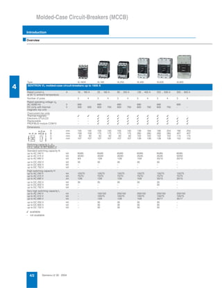
  • 1. Siemens LV 30 · 20044/2 Molded-Case Circuit-Breakers (MCCB) Introduction 4 ■Overview ✓ available – not available Type VL160X VL160 VL250 VL400 VL630 VL800 SENTRON VL molded-case circuit-breakers up to 1600 A Rated current In at 50 °C ambient temperature A 16 ... 160 A 25 ... 160 A 80 ... 250 A 126 ... 400 A 252 ... 630 A 320 ... 800 A Number of poles 3 4 3 4 3 4 3 4 3 4 3 4 Rated operating voltage Ue AC 50/60 Hz DC (only with thermal- magnetic trip unit) V V 690 500 500 690 600 750 690 600 750 690 600 750 690 600 750 690 – – Overcurrent trip units Thermal-magnetic Electronic ETU/LCD Replaceable PROFIBUS module COM10 ✓ – – – ✓ – – – ✓ ✓ ✓ ✓ ✓ ✓ ✓ ✓ ✓ ✓ ✓ ✓ ✓ ✓ ✓ ✓ ✓ ✓ ✓ ✓ ✓ ✓ ✓ ✓ ✓ ✓ ✓ ✓ ✓ ✓ ✓ ✓ – ✓ ✓ ✓ – ✓ ✓ ✓ Dimensions A B C D mm mm mm mm 105 158 82 107 140 158 82 107 105 175 82 107 140 175 82 107 105 175 82 107 140 175 82 107 139 280 102 139 184 280 102 139 190 280 102 139 254 280 102 139 190 407 115 152 254 407 115 152 Switching capacity Icu/Ics r.m.s. value, to IEC 60947-2 Standard switching capacity N up to AC 240 V up to AC 415 V up to AC 690 V kA kA kA 65/65 40/40 8/4 65/65 40/40 12/6 65/65 40/40 12/6 65/65 45/45 15/8 65/65 45/45 20/10 65/65 50/50 20/10 up to DC 250 V up to DC 600 V up to DC 750 V kA kA kA 30 – – 30 – – 30 – – 30 – – 30 – – – – – High switching capacity H up to AC 240 V up to AC 415 V up to AC 690 V kA kA kA 100/75 70/70 12/6 100/75 70/70 12/6 100/75 70/70 12/6 100/75 70/70 15/8 100/75 70/70 30/15 100/75 70/70 30/15 up to DC 250 V up to DC 600 V up to DC 750 V kA kA kA 30 – – 30 – – 30 – – 30 – – 30 30 – – – – Very high switching capacity L up to AC 240 V up to AC 415 V up to AC 690 V kA kA kA – – – 150/150 100/75 12/6 200/150 100/75 12/6 200/150 100/75 15/8 200/150 100/75 35/17 200/150 100/75 35/17 up to DC 250 V up to DC 600 V up to DC 750 V kA kA kA – – – 30 30 30 30 30 30 30 30 30 30 30 30 – – – NSE0_01159 D CA B
  • 2. Siemens LV 30 · 2004 4/3 Molded-Case Circuit-Breakers (MCCB) Introduction 4 VL1250 VL1600 3VF2 3VF3 3VF4 3VF5 3VF6 3VF7 3VF8 SENTRON VL molded-case circuit-breakers up to 1600 A Molded-case circuit-breakers up to 2500 A 400 ... 1250 A 640 ... 1600 A 16 ... 125 160, 205, 225 220/250 315/400 500/630/800 800/1250 1600/2000, 2500 3 4 3 4 3 and 4 3 and 4 3 and 4 3 and 4 3 and 4 3 and 4 3 and 4 690 – 690 – up to 415 – 690 750 690 750 690 750 690 750 690 – 690 – – ✓ ✓ ✓ – ✓ ✓ ✓ – ✓ ✓ ✓ – ✓ ✓ ✓ ✓ – – – ✓ ✓ – – ✓ – – – ✓ ✓ – – ✓ ✓ – – ✓ ✓ – – ✓ ✓ – – 229 407 153 209 305 407 153 209 229 537 153 209 305 537 153 209 76/102 124 68 73 105/140 153 81 105 105/140 254 97 126 140/183 258 97 126 210/280 273 97 141 210/280 406 140 183 394/508 407 229 305 65/35 50/25 20/10 65/35 50/25 20/10 65/33 18/9 – 85/851 ) 40/401 ) 12/6 85/85 40/40 14/7 85/85 45/45 20/10 85/852 ) 45/452 ) 20/102) 85/85 50/50 20/10 – – – – – – – – – – – – 20/10 20/10 20/10 20 20 20 20 20 20 20 20 20 – – – – – – 75/50 70/35 30/15 100/50 70/35 30/15 – – – 100/100 70/70 14/7 100/100 70/70 18/9 100/100 70/70 25/13 100/100 70/70 25/13 100/100 70/50 25/13 135/100 70/50 25/13 – – – – – – – – – 20/10 20/10 20/10 20 20 20 20 20 20 20 20 20 – – – – – – 200/100 100/50 35/17 200/100 100/50 35/17 – – – 200/150 100/75 18/9 200/150 100/75 22/11 200/150 100/75 35/18 200/150 100/75 35/18 200/100 100/50 35/18 200/100 100/50 35/18 – – – – – – – – – 20/10 20/10 20/10 20 20 20 20 20 20 20 20 20 – – – – – – 1) or up to AC 240 V: 40/40 kA and up to AC 415 V: 25/25 kA. 2) or at In = 800 A; up to AC 240 V: 65/33 kA; up to AC 415 V: 50/25 kA; up to 690 V: 20/10 kA.
  • 3. Siemens LV 30 · 20044/4 SENTRON VL Circuit-Breakers up to 1600 A General data 4 ■Overview $ Withdrawable/plug-in base % Side walls for withdrawable version & Phase barriers ( Flared front busbar connecting bars ) Straight connecting bars * Multiple supply terminal for Al/Cu + Box terminal for Cu , Extended terminal cover - Standard terminal cover . Masking frame/cover frame for door cut-out / Motorized operating mechanism with spring energy store 0 Front-operated rotary operating mechanism 1 Door-coupling rotary operating mechanism 2 SENTRON VL circuit-breaker 3 Internal accessories 4 Electronic overcurrent trip unit 5 Thermal/magnetic overcurrent trip unit 6 RCD module 7 Rear terminals – flat and round 8 COM10 communication module to the PROFIBUS DP 9 Manual tester for electronic trip unit . 0 / 1 .
  • 4. Siemens LV 30 · 2004 4/5 SENTRON VL Circuit-Breakers up to 1600 A General data 4 - * ( , %& ) 9 $ 2 4 3 - , & 6 5 ( 7 * 8 + ) +
  • 5. Siemens LV 30 · 20044/6 SENTRON VL Circuit-Breakers up to 1600 A General data 4 ■Benefits • The compact design of the SENTRON VL circuit-breakers cou- pled with excellent characteristics fulfills the high demands of today's electrical distribution systems. • These circuit-breakers offer a broad product range, improved technology, space savings and easy operation. • They are available both in thermal/magnetic (16 A to 630 A) and in electronic versions (63 A to 1600 A). ■Area of application The different versions of SENTRON VL circuit-breakers are suit- able for the following applications: • Incoming and outgoing circuit-breakers in distribution systems • Switching and protection devices for motors, transformers and capacitors • Main control switches and EMERGENCY-STOP switches in conjunction with lockable rotary operating mechanism and ter- minal covers. The SENTRON VL circuit-breakers are available in the following versions: 1. For system protection (in 3 and 4-pole versions) The overload and short-circuit releases are designed for the pro- tection of cables, leads and non-motor loads. 2. For motor protection (in 3-pole versions) The overload and short-circuit releases are designed for opti- mized protection and direct starting of three-phase squirrel-cage motors. The circuit-breakers for motor protection are susceptible to phase failure and feature an adjustable trip class. The over- current trip units operate with a microprocessor. 3. For starter combinations (in 3-pole versions) These circuit-breakers are used both for short-circuit protection as well as for isolating functions, which may be required in starter combinations consisting of circuit-breakers, overload re- lays and motor contactors. These circuit-breakers exclusively feature adjustable, instantaneous short-circuit releases. 4. As non-automatic circuit-breakers (in 3- and 4-pole versions) These circuit-breakers can be used as feeder circuit-breakers, main control switches or disconnecting switches without over- load protection. They incorporate an integrated short-circuit self- protection system, eliminating the need for back-up fuses. Standards and specifications SENTRON VL circuit-breakers comply with: IEC 60947-1, EN 60947-1, DIN VDE 0660, Part 100, IEC 60947-2, EN 60947-2, DIN VDE 0660, Part 101. Isolating features to IEC 60947-3, EN 60947-3. Please contact Siemens for details of other standards. The overcurrent trip units of the circuit-breakers for motor protec- tion also fulfill IEC 60947-4-1, DIN VDE 0660, Part 102. Main control switches to EN 60204 or DIN VDE 0113 (see Area of application). EMERGENCY-STOP switches to EN 60204 or DIN VDE 0113 (see Area of application). Operating conditions The SENTRON VL circuit-breakers are climate-proof. They are intended for use in enclosed areas where no severe op- erating conditions (e.g. dust, corrosive vapors, damaging gases) are present. When installed in dusty and damp areas, suitable enclosures must be provided. Utilization category All SENTRON VL circuit-breakers satisfy utilization category A. Degree of protection RCD module The RCD module is designed for retrofitting to the switch. It can also be retrofitted by the customer. The combination of SENTRON VL circuit-breaker and RCD module can be fed from the top or bottom. All SENTRON VL circuit-breakers with RCD modules are avail- able with auxiliary switches, alarm switches, undervoltage and shunt releases. Protection of plant and equipment against overload or damage by ground faults (ground fault protection). The RCD module trips the circuit-breaker through vectorial sum- mation current formation for all phase currents if the vectorial sum of the currents in the poles (= the ground fault current) ex- ceeds the pre-set response and delay time values. AC currents and pulsating DC currents are measured (CBR, design A to EN 60947-2). Circuit-breaker IP20 Masking frame IP40 Terminal covers IP30 With front rotary operating mechanism IP40 With door-coupling rotary mechanism IP65 With motorized operating mechanism IP30 With motorized operating mechanism and masking frame for the door cut-out IP40 Plug-in base/withdrawable version IP20
  • 6. Siemens LV 30 · 2004 4/7 SENTRON VL Circuit-Breakers up to 1600 A General data 4 Switching of DC currents The VL160X to VL630 circuit-breakers (for system protection with TM, for starter combinations, non-automatic circuit-breakers) can also be used for DC switching and protection applications. The VL160 to VL1600 circuit-breakers with electronic trip units (ETU) are not suitable for DC applications. However, the maximum permitted DC voltage for each current path needs to be taken into account for DC switching applica- tions. For voltages above 250 V, a series connection of 2 or 3 current paths is required. As the current has to flow through all of the current paths, the fol- lowing connections are recommended in order to satisfy the thermal tripping characteristics. With DC applications, the response values of the instantaneous short-circuit releases ("I" trip units) are increased by 30 to 40%. ■Design • Rated current range from 16 A to 1600 A • Different switching capacity for each frame size • No derating or loss of performance up to 50°C • Electronic overcurrent trip units from size 160 A (VL160), partic- ularly for time-based discrimination and ground-fault protec- tion • 2 families of internal accessories • Full range of external accessories e.g. terminals for aluminum cable. All circuit-breakers are supplied with integrated overcurrent trip units. The SENTRON VL160X to VL1600 circuit-breakers are avail- able with busbar connection pieces or box terminals (up to 400 A; see Page 4/10). Auxiliary switches/alarm switches or aux- iliary releases can be easily adapted by the customer, or they are also available ready installed if required. The switching capacity is shown on the front of every circuit- breaker. • Standard switching capacity: Icu = 40 to 50 kA at AC 50/60 Hz 380/415 V • High switching capacity: Icu = 70 kA at AC 50/60 Hz 380/415 V • Very high switching capacity: Icu = 100 kA at AC 50/60 Hz 380/415 V Recommended connection Maximum permitted DC voltage Ue Remarks For 3 and 4-pole circuit-breakers DC 250 V 2-pole switching (ungrounded system) If there is no possibility of a ground fault, or if every ground fault is rectified immediately (ground-fault monitoring), then the maximum permitted DC volt- age is 600 V. DC 500 V 2-pole switching (grounded system) The grounded pole is always assigned to the individual current path, so that there are always 2 current paths in series in the event of a ground fault. DC 600 V 1-pole switching (grounded system) 3 current paths in series. The grounded pole is assigned to the unconnected current path. DC 750 V 1-pole switching (grounded system) 4 current paths in series. The grounded pole is assigned to the unconnected current path. L NSE0_00741 M L L NSE0_00742 M L L NSE0_00743 M L L L NSE0_00744 M N Standard (40 to 50 kA) H High (70 kA) L Very high (100 kA)
  • 7. Siemens LV 30 · 20044/8 SENTRON VL Circuit-Breakers up to 1600 A General data 4 Connection The SENTRON VL160X to VL160 circuit-breakers are equipped with incoming and outgoing terminals which are suitable for stranded conductors, flexible copper rails and conductors with end sleeves. Different supply terminals are available for VL630 to VL1600 (sizes 630 A to 1600 A). Appropriate accessories for screw connection to fixed and flex- ible copper bars or cables are available for SENTRON VL160X to VL1600 circuit-breakers. SENTRON VL160X to VL1600 circuit-breakers can be equipped with connecting bars. These are intended for connection of stan- dard busbars and can be used for front or rear connection. The SENTRON VL1600 circuit-breaker is supplied with front con- necting bars. The incoming and outgoing connections for the circuit-breaker can be freely selected. The electrical specifications remain the same. The infeed for circuit-breakers with RCD modules can be con- nected above or below. Bare conductors at the top connections must be insulated in the arc quenching space that is necessary above the arcing cham- bers. Phase barriers or terminal covers can be used for this pur- pose. For the SENTRON VL160X to VL1600 circuit-breakers, the con- nections for the internal accessories (auxiliary releases, auxiliary switches and alarm switches) are supplied with terminal screws. The auxiliary releases (shunt releases and undervoltage re- leases), auxiliary switches and alarm switches for all SENTRON VL circuit-breakers can be connected easily and directly. The motorized operating mechanisms with spring energy stores are always equipped with terminals. The leading auxiliary switches for the rotary operating mechanisms are always sup- plied with connecting leads. SENTRON VL160X circuit-breakers The main components of the SENTRON VL160X circuit-breakers are the three conducting paths with the incoming and outgoing terminals. The fixed and moving contacts are designed in such a way that the contacts are magnetically repelled if there is a short-circuit. In conjunction with the arcing chambers, a dy- namic impedance is created that causes current limiting due to a reduction in the damaging effects of I2 t and Ip energy that arises during short-circuits. The trip unit is preassembled and equipped with fixed or adjust- able overload releases as well as with fixed short-circuit releases for each pole. The circuit-breaker is trip-free. To the right and left of the operating mechanism, the double-in- sulated accessory compartments are situated for the auxiliary releases and auxiliary switches. SENTRON VL160 to VL630 circuit-breakers The arrangement of the current path, main contact and switch- ing mechanism corresponds to that of the SENTRON VL160X circuit-breakers. The trip units for the SENTRON VL160 to VL630 have the follow- ing features: • The trip units are available in thermal-magnetic and electronic versions. They can be replaced by the customer using a spe- cial tool. • The thermal-magnetic trip units have adjustable overload and short-circuit releases. SENTRON VL800 to VL1600 circuit-breakers The arrangement of the current paths and switching mecha- nisms corresponds with those of the SENTRON VL160X to VL630 circuit-breakers. The SENTRON VL800 to VL1600 circuit-breakers are only avail- able with electronic trip units. As is the case for all versions of the SENTRON VL circuit-break- ers with electronic trip units, the current transformers are in the same enclosure as the trip units. They send a signal which is proportional to the load current to the electronic overcurrent trip- ping unit. All SENTRON VL circuit-breakers with electronic trip units mea- sure the actual r.m.s. current. This type of measurement is the most accurate method. Currents in today's electrical distribution systems with many harmonics are evaluated reliably. Overcurrent trip unit systems 1. Overcurrent trip unit system of the SENTRON VL160X to VL630 circuit-breakers - thermal-magnetic The overcurrent and short-circuit releases function with bimetal- lic and magnetic trip units. They are available in fixed set or ad- justable versions. The four-pole circuit-breakers for system protection can be equipped with overcurrent trip units for all four poles or without an overcurrent trip unit for the fourth pole (N). From 100 A and higher, the trip units for the fourth pole (N) are set to 60% of the current for the 3 main current paths, so that safe protection for neutral conductors with a reduced cross-section is ensured. The circuit-breakers for starter combination applications are usually combined with a motor contactor and a suitable overload relay. The non-automatic circuit-breakers have an integrated short- circuit self-protection system eliminating the need for back-up fuses. These circuit-breakers have no overload protection. Four- pole circuit-breakers do not have a short-circuit release for the fourth pole (N). 2. Overcurrent trip unit system for SENTRON VL160 to VL1600 circuit-breakers, electronic, ETU The electronic overcurrent trip unit system consists of: • 3 current transformers • Evaluation electronics with microprocessor • Tripping solenoid. For SENTRON VL160 and VL250, the tripping solenoid is in- stalled in the left accessory compartment. An auxiliary power supply is not necessary for the release. A minimum load current of approx. 20 % of the corresponding rated current In of the circuit-breaker is required to activate the microprocessor trip units. At the output of the electronic overcurrent trip unit module there is a tripping solenoid which trips in the case of overload or short- circuit. Abbreviations (functions) L, S, I, G designations in accordance with IEC 60947 L = Long Time Delay = Overload protection S = Short Time Delay = Short-circuit protection (short-time delayed) I = Instantaneous = Short-circuit protection (instantaneous) G = Ground Fault = Ground-fault protection
  • 8. Siemens LV 30 · 2004 4/9 SENTRON VL Circuit-Breakers up to 1600 A General data 4 VL160X to VL1600 overcurrent trip units No rated current reduction up to 50 °C Adjustable neutral conductor protection with LCD ETU 42 1) TM up to 630 A Internal accessories (auxiliary switches, undervoltage releases, shunt releases) The SENTRON VL circuit-breakers can be supplied with all the internal accessories (e.g. auxiliary switches, undervoltage re- leases or shunt releases). The available versions can be found in the tables with the Order No. prefixes. Fixed-mounting, plug-in or withdrawable version The fixed-mounting circuit-breaker is the basic version. This can be converted very easily into a plug-in or withdrawable version with the aid of the appropriate mounting set. This set contains blade contacts, a locking pin and terminal covers for the plug-in version. The set for the withdrawable version also contains side covers and a moving mechanism. Even with the masking frame mounted, it is still possible to move using the handle with the door closed. Operating mechanisms The basic versions of the SENTRON VL circuit-breakers are equipped with a toggle lever as an operating mechanism which is also used as a position indicator. In addition to "ON" and "OFF", "Tripped" is also indicated. The toggle lever assumes the "tripped" position when the internal tripping mechanism is activated by an overcurrent trip opera- tion, e.g. an overload or short-circuit. The activation of an under- voltage release or shunt release also causes the toggle lever to assume the "tripped" position. The toggle lever must be put into the "OFF/RESET" position before the circuit-breakers can be re- closed. It will then be possible to reset the internal release mech- anism and reclose the main contacts on the circuit-breaker (see figure). A toggle handle extension is supplied with the SENTRON VL1250 and VL1600 circuit-breakers. This accessory must be ordered separately for SENTRON VL400 to VL800 circuit-breakers, if required. Front-operated rotary operating mechanisms These operating mechanisms have been designed for direct mounting to the circuit-breaker and change the toggle lever movement from a linear to a rotary motion. A leading voltage can be applied to the undervoltage release of a circuit-breaker with leading auxiliary switches which makes the circuit-breaker ready-to-close. Door-coupling rotary operating mechanisms (complete operating mechanisms) Door-coupling rotary operating mechanisms and removable covers are available for circuit-breakers which are installed into control cabinets and distribution boards. These are supplied as complete sets, including an articulated-shaft mechanism. With regard to the switching status indication and the "RESET" position, the same applies to the rotary operating mechanisms as to the toggle lever. The position of the operator lever (toggle) indicates the status. All rotary operating mechanisms can be locked in the OFF posi- tion with the help of suitable padlocks. This means that all SENTRON VL circuit-breakers which have these operating mechanisms as well as the corresponding terminal covers can be used as main switches. Toggle lever operating mechanism positions Rotary operating mechanism secured with a padlock Setting options L S (i) S (t) I G ✓ 1 ) LI 1 10 ✓ ✓ TM 1 ) 4/13 ✓ 1 ) LI 0,8-1 10 ✓ ✓ TM 1 ) 4/13 ✓ 1 ) LI 0,8-1 5-10 ✓ ✓ TM 1 ) 4/13 ✓ ✓ LI 0,4-1 1,25-11 ✓ ✓ ✓ ETU 10 M 4/14 ✓ LI 0,4-1 1,25-11 ✓ ✓ ETU 10 4/13 ✓ LIG 0,4-1 1,25-11 In ✓ ✓ ETU 12 4/13 ✓ ✓ LSI 0,4-1 1,5-10 0-0,5 11 ✓ ✓ ETU 20 4/13 ✓ ✓ LSIG 0,4-1 1,5-10 0-0,5 11 In ✓ ✓ ETU 22 4/14 ✓ LI 0,4-1 1,25-11 ✓ ✓ ✓ ETU 30 M 4/14 ✓ ✓ LSI 0,4-1 1,5-10 0-0,5 1,25-11 ✓ ✓ ✓ ✓ LCD ETU 40 M 4/14 ✓ LI/LSI 0,4-1 1,5-10 0-0,5 1,25-11 ✓ ✓ ✓ LCD ETU 40 4/14 ✓ LSIG 0,4-1 1,5-10 0-0,5 1,25-11 adjustable ✓ ✓ ✓ LCD ETU 42 4/15 Systemprotection Motorprotection Generatorprotection Function Thermalimage Phasefailure Communication-capable Thermal-magnetic tripunit(TM) Electronic tripunit(ETU) Electronictripunit withLCDdisplay(LCDETU) Tripunit Technicalspecifications seePage NSE0_00038a OFF RESET ON Tripped NSE0_00699
  • 9. Siemens LV 30 · 20044/10 SENTRON VL Circuit-Breakers up to 1600 A General data 4 Motorized operating mechanism with spring energy store The SENTRON VL160X to VL1600 circuit-breakers (sizes 160 to 1600 A) can be equipped with motorized operating mechanisms for remote opening and closing during operation. These motorized operating mechanisms with spring energy stores for SENTRON VL160X to VL800 circuit-breakers have a stored-energy feature (for synchronization) with a maximum ON period of tE ≤ 100 ms. The SENTRON VL1250 and VL1600 cir- cuit-breakers are motor driven (tE ≤ 5 s). In addition, they permit remote opening of the circuit-breaker. The motorized operating mechanisms with spring energy store are always supplied with a locking device for padlocks. Optional safety locks are also available. These devices can be used to block the operating mechanism electrically and mechanically. All remote-controlled mechanisms are equipped with a manual operation option for maintenance purposes. Main connections, basic equipment and options - = scope of supply x = available – = not available SENTRON VL160X and VL160 circuit- breakers SENTRON VL250 to VL1250 circuit- breakers SENTRON VL1600 circuit-breakers Box terminal for copper cables or busbars Connection with screw connection (available with direct cable lug connec- tion on VL160X, VL160, VL250, VL400) Connection to front busbar connecting bars For conductor cross-sections see Page 4/17 NSE0_00700 NSE0_00701 NSE0_00702 Main connections Circuit-breakers Connection overview and further options Box terminals Connection with screw connection with metric thread Circular conductor terminal (for Al/Cu cables) Rear-mounting terminals Front-accessible connecting bars VL160X o x x x x VL160 o x x x x VL250 x o x x x VL400 x o x x x VL630 – o x x x VL800 – o x x x VL1250 – o x x x VL1600 – x – x o
  • 10. Siemens LV 30 · 2004 4/11 SENTRON VL Circuit-Breakers up to 1600 A General data 4 Auxiliary releases and auxiliary switches Undervoltage releases, leading auxiliary switches If there is no voltage present, closing of the breaker is not possi- ble. If voltage is not applied to the trip unit, operation of the circuit-breaker will result in no-load switching. Frequent re-tripping should be avoided because of its adverse effect on the service life of the circuit-breaker. All undervoltage releases have been designed and tested to fulfill all applicable requirements in accordance with IEC 60947 (release voltage 0.70 to 0.35 Ue, response voltage 0.85 to 1.10 Ue). A leading voltage can be applied to the undervoltage release of a circuit-breaker with leading auxiliary switches which makes the circuit-breaker ready-to-close. For SENTRON VL circuit-breakers, the leading auxiliary switch can be supplied with the front rotary operating mechanism or complete operating mechanism. For more detailed information please refer to the selection and ordering tables for accessories. Shunt release The shunt release is used for remote tripping of the circuit- breaker. The coil of the shunt release is designed for short-time operation only. A coil trip is implemented internally. These devices operate in compliance with IEC 60947 (tripping voltage 0.70 to 1.10 Ue). It is not permissible to apply a continuous trip command to a shunt release to prevent closing when the circuit-breaker is tripped. A central tap is provided as standard for checking the conduc- tivity of the coil. Auxiliary switch Auxiliary switches are used for indication and control. The differ- ent combination options for the auxiliary switches are shown in the diagram above. Alarm switch The alarm switches (AS) are active when the circuit-breaker has been tripped due to an overcurrent e.g. overload or short-circuit. However, they are also activated if the circuit-breaker has been tripped by a shunt release or undervoltage release. Installing auxiliary/alarm switches (see diagram) The configuration possibilities for circuit-breakers with auxiliary and alarm switches depend on the mounting position of the aux- iliary/alarm switches on the circuit-breaker and on the accessory groups (1 or 2) of the circuit-breakers. PLC control The auxiliary and alarm switches can be used to send signals to programmable controllers. These switches are part of the Siemens 3SB3 range. Leading auxiliary switches The leading auxiliary switches OFF to ON or ON to OFF are avail- able as a retrofit set for rotary operating mechanisms. Possible complements for the insulated accessory subsections in the SENTRON VL circuit-breakers Before ordering, use the table above to check whether the required com- bination of shunt releases, undervoltage releases and auxiliary/alarm switches is feasible. RCD module • Easy mounting • Installation kit for lateral assembly to DIN 50023 for SENTRON VL160X circuit-breakers under Order No. 3VL9112-5GB30/3VL9112-5GB40 • A tripping button enables the function of the integrated RCD module to be tested. • Protruding reset/tripping button (prevents the circuit-breaker from being reclosed before the reset/tripping button has been reset) • Circuit for remote-controlled tripping of the circuit-breaker does not require an additional external voltage supply (for SENTRON VL160 to VL400 circuit-breakers). • LED displays which enable visual monitoring of the RCD module - Green ≤ 25% IΔ of IΔn - Green + yellow 25% < IΔ = 50% of the set IΔn - Green + yellow + red IΔ ≥ 50% of the set IΔn • RCD alarm switch (changeover contact) for VL160 to VL400 to indicate a tripping operation by the RCD module • AC 690 V application • "Power disconnect" enables electrical testing without discon- necting the cables • The functional properties of the circuit-breaker are not adversely affected by the addition of the RCD module • Internal power supply, no external voltage. (For diagrams see Page 4/16). NSE0_00584d U< VL160X 3VL1 Max. 3 HS Max. 3 HS VL160 3VL2 VL250 3VL3 VL400 3VL4 VL630 3VL5 VL800 3VL6 VL1250 3VL7 VL1600 3VL8 Max. 2 HS + 1 AS Max. 2 HS + 1 AS Max. 3 HS Max. 3 HS Max. 3 HS Max. 3 HS Max. 4 HS Max. 4 HS Max. 4 HS Max. 4 HS Max. 3 HS Max. 2 HS + 1 AS Max. 3 HS Max. 2 HS + 1 AS Max. 3 HS Max. 2 HS + 1 AS Max. 4 HS Max. 2 HS + 2 AS Max. 4 HS Max. 2 HS + 2 AS Max. 4 HS Max. 2 HS + 2 AS Max. 4 HS Max. 2 HS + 2 AS U< Max. 3 HS Max. 2 HS + 1 AS U< Max. 3 HS Max. 2 HS + 1 AS U< Max. 3 HS U< Max. 4 HS U< Max. 4 HS U< Max. 4 HS U< Max. 4 HS U< N 4th pole Left accessory compartment VL160X with RCD: Left accessory compartment is equipped with tripping solenoid VL160/VL 250 with electronic overcurrent release (ETU or LCD ETU): Left accessory compartment is equipped with tripping solenoid Shunt trip or undervoltage release HS one auxiliary switch 1 NO or 1 NC AS one alarm switch 1 NO or 1 NC Note: Maximum 6 switching elements (HS) per circuit-breaker VL160X to VL400 Maximum 8 switching elements (HS) per circuit-breaker VL630 to VL1600 Right accessory compartment Accessory compartment
  • 11. Siemens LV 30 · 20044/12 SENTRON VL Circuit-Breakers up to 1600 A General data 4 ■Functions Current limitation The SENTRON VL circuit-breakers utilize the design principle of magnetic repulsion of the contacts. The contacts open before the anticipated peak value of the short-circuit current is achieved. The current-limiting effects of the SENTRON VL circuit-breakers provide effective protection for system compo- nents against the thermal and dynamic effects of the short- circuit current in the event of an electrical fault. Ground-fault protection Ground-fault releases "g" sense fault currents that flow to ground and that can cause fire in the plant. Several circuit-breakers con- nected in series can provide graduated discrimination by means of the adjustable delay time. The following measurement methods can be used to detect neu- tral conductor and ground-fault currents: Vectorial summation current formation (measurement method 1) Ground-fault detection in symmetrically loaded systems The three phase currents are evaluated with the help of the vec- torial summation current. Ground-fault detection in asymmetrically loaded systems The neutral conductor current is measured directly. For the three-pole circuit-breakers this measurement is only evaluated for ground-fault protection; for four-pole circuit-breakers it is also evaluated for neutral conductor overload protection. The overcurrent trip unit determines the ground-fault current for the three phase currents and neutral conductor current by means of vectorial summation current formation. For 4-pole circuit-breakers, the fourth current transformer for the neutral conductor is installed internally. 3-pole circuit-breaker, current transformer in the neutral conductor 4-pole circuit-breaker, current transformer installed internally Direct detection of the ground-fault current via a current trans- former in the grounded neutral point of the transformer (mea- surement method 2) The current transformer is installed directly in the grounded neu- tral point of the transformer. Three-pole circuit-breakers, current transformers in the grounded neutral point of the transformer. For RCD module, see Pages 4/44 and 4/45. For external current transformer, see Page 4/55. Transformer protection The SENTRON VL circuit-breakers protect energy distribution systems against overload and short-circuit on the low-voltage side of the infeed transformer. The resulting requirements with re- spect to current-based and/or time-based discrimination are reli- ably fulfilled by the SENTRON VL circuit-breakers for system pro- tection (equipped with thermal-magnetic (TM) or electronic overcurrent trip units (ETU or LCD ETU). L1 L2 L3 PE 3VL NSE0_00685 L1 L2 L3 N PE 3VL T5 NSE0_00686 L1 L2 L3 N PE 3VL NSE0_00687 L1 L2 L3 3VL T6 PE N NSE0_00688
  • 12. Siemens LV 30 · 2004 4/13 SENTRON VL Circuit-Breakers up to 1600 A General data 4 Thermal-magnetic overcurrent trip unit Electronic overcurrent trip units ETU 1) Depending on size, see Page 4/23 (3-pole) and Page 4/30 (4-pole) Application: system protection – TM, LI/LIN function Overload protection (fixed), short-circuit protection (fixed); see selection table for VL160X (trip units installed in the switch enclosure) Application: system protection – TM, LI/LIN function Overload protection (adjustable IR = 0.8 to 1 × In), short-circuit protection (fixed); see selection tables for VL160X (trip units installed in the switch enclosure) Application: system protection – TM, LI/LIN function Overload protection (adjustable IR = 0.8 to 1 × In), short-circuit protection (adjustable Ii = 5 to 10 × In, for VL160 to VL630) L I NSE0_00689 2 4 6 63A OFF CAT.A 50° C TM ~= NSE-00539 L I NSE0_00690 I 1.0 .8 RInx 63A OFF CAT.A 50° C TM ~= 2 4 6 NSE-00540 L I NSE0_00691 2 5 6 7 nx 10 9 8 i 4 6 TM 50 C CAT.A =160An x n .8 DC R 1.0 16 I I I ~ = NSE-00541 I I iR I I For types VL160 to VL1600 General No auxiliary voltage for tripping unit required All ETUs have a thermal image Flashing green LED indicates faultless operation of microprocessor Overload status (I > 1.05 × IR) is indicated by continuous yellow LED (alarm) Integrated self-test function Female connector for test unit Application: system protection – ETU10, LI/LIN function Overload protection IR = 0.4; 0.45; 0.5 to 0.95; 1 × In, time-lag class tR = 2.5 to 30 Short-circuit protection (instantaneous) Ii = 1.25 to 11 × In 1 ) Application: system and generator protection – ETU20, LSI/LSIN function Overload protection IR = 0.4; 0.45; 0.5 to 0.95; 1 × In, Short-circuit protection (short-time delayed) Isd = 1.5 to 10 × IR, tsd = 0 to 0.5 s, I2 t selectable on/off Short-circuit protection (instantaneous) Ii = 11 × In (fixed)1) Application: system protection – ETU12, LIG/LING function Overload protection IR = 0.4; 0.45; 0.5 to 0.95; 1 × In, time-lag class tR = 2.5 to 30 Short-circuit protection (instantaneous) I = 1.25 to 11 × In 1 ) Ground-fault protection: Measurement method no. 1: (GR) vectorial summation current formation for the currents of the three phases/and neutral conductor (four-conductor systems); IΔn = In, versions "AC", "AD", "BC", "BD" (for Order No. supplements see Page 4/25 or 4/31) Measurement method no. 2: (GGND) direct detection of ground-fault current via current transformer installed in grounded neutral point, Ig = In (instantaneous); version "AJ" (for Order No. supplements see Page 4/25) L I NSE0_00691 CAT.A =250A ~1 n 25 AB nx1 R1Alarm X3 >1.05 25 AB .45 .6 .9 1.0 .95 .7 .8 .4 .63 30 14 Rt 20.5 (S)Rt 25 R1 i1 17 8 1 i nx1 6 2.5 4 10 8 2 1.25 1.5 4 3 10 11 5 6 Active NSE0_00542 L S I NSE0_00920 Alarm >1.05 CAT.A 25 AE X3 .45 =250A .6 1.0 IR .95 .9 .4 nI nIx .7 .63 .8 10 8 Isd sdt 7.5 ~ sdRII 5 6 .2 (S) t 22 tsd I 1.5 ON xI 2.5 4 3 R 0 OFF t2I .1 .2 .4 Active .3 .3 .4 .5 .1 25 AE NSE-00543 L IG NSE0_00693 .95 CAT.A X3 >1.05 25 AD R x n .8 .9 Alarm (S)t 1.0 2.530.4 .5 .45 .7 .63 R iR Rt 1014 17 25 20 8 6 4 i 1.25 11 Active 5 x n 6 8 10 4 2 3 1.5 =250An ~ 25 ADn n= NSE-00544
  • 13. Siemens LV 30 · 20044/14 SENTRON VL Circuit-Breakers up to 1600 A General data 4 Electronic overcurrent trip units LCD ETU 1) Depending on size, see Page 4/23 (3-pole) and Page 4/30 (4-pole) Application: system and generator protection – ETU22, LSIG/LSING function Overload protection IR = 0.4; 0.45; 0.5 to 0.95; 1 × In, Short-circuit protection (short-time delayed) Isd = 1.5 to 10 × IR, tsd = 0 to 0.5 s, I2 t selectable on/off Short-circuit protection (instantaneous) Ii = 11 × In (fixed)1) Ground-fault protection: Measurement method no. 1: (GR) vectorial summation current formation for the currents of the three phases/and neutral conductor (4-conductor systems); IΔn = In, versions "AG", "AH", "BG", "BH" (for Order No. supplements see Page 4/25 or 4/31) Measurement method no. 2: (GGND) direct detection of ground-fault current via current transformer, Ig = In (instantaneous); version "AK" (for Order No. supplements see Page 4/25) Application: motor protection – ETU10M, LI function Overload protection adjustable in small steps IR = 0.41; 0.42 to 0.98; 0.99; 1 × In, trip class tc = 10 (fixed) Thermal image Short-circuit protection (instantaneous) Ii = 1.25 to 11 × In 1 ) with phase failure sensitivity Application: motor protection – ETU30M, LI function Overload protection adjustable in small steps IR = 0.41; 0.42 to 0.98; 0.99; 1 × In, trip class tc = 10 A, 10, 20, 30 Thermal image Short-circuit protection (instantaneous) Ii = 6 to 11 × In with phase failure sensitivity NSE0_00921 L S IG sd .95 25 AG CAT.A X3 .9 Ix n .8 Alarm >1.05 RI sd .5 .63.7 .6 sdt RI Isd .45 .41.0 I 4 7 6 5 Ix 2.5 R3 1.5 8 10 t 2 OFF Active I t .5 ON .2 .1 .2 .4 .3 .4 (S) 2 .3 .1 0 I 2 t = 250AnI ~ 25 AGn NSE-00545 nI = I NSE0_00943 L I Alarm 25 AP CAT.A >1.05 X3 I .100.4 0.70.8 0.9 + xI 0.6 0.5 R n .07.06 .08 .09 IEC 60947-4 EN 60947-4i I 11.01 1.25 10 .04 .05 .03 .02 6 R I i I 8 3 1.5 5 4 Active Inx 2 =250AnI ~ 25 AP NSE-00546 L I NSE0_00691 nx Alarm >1.05 0.4 i =11x NSE0_01160 X3 0.5 0.6 0.70.8 0.9 R .10 .01 .02 .03 .04 .05.06 .07 .08 .09 TC i=6x n Active i=8x n 10 20 30 10 20 30 10 2030 10A n25 AS General No auxiliary voltage for trip unit required Current indicator Illuminated LCD display indicates faultless operation of microprocessor Overload status (I > 105% IR) is indicated by "overload" on the LCD display User-friendly, menu-driven setting of protection parameters in absolute ampere values via keys Integrated self-test function Female connector for test/programming device For communication link to PROFIBUS DP see Section 3 "Communication-capable circuit-breakers". Application: system protection – ETU40, LSI functions and motor protection – ETU40M, LSI/LSIN function Overload protection IR = 0.4 to 1 × In, trip class tc = 2.5 to 30 On/off selectable thermal image Short-circuit protection (short-time delayed) Isd = 1.5 to 10 × IR, tsd = 0 to 0.5 s, I2 t selectable on/off Short-circuit protection (instantaneous) Ii = 1.25 to 11 × In 1 ) NSE0_00944 L I ESC L1=178; L2=181 L3=179; N=0 CAT.A =250AnI ~ 25 CLn nI = I NSE-00547
  • 14. Siemens LV 30 · 2004 4/15 SENTRON VL Circuit-Breakers up to 1600 A General data 4 1) Depending on size, see Page 4/23 (3-pole) and Page 4/30 (4-pole) ■Integration Mounting The SENTRON VL circuit-breakers are suitable for use in open and enclosed switchboards and distribution systems. The rec- ommended mounting positions for the SENTRON VL circuit- breakers are shown in the diagrams under "Technical specifica- tions, permissible mounting positions". Application: system protection – ETU42, LSIG/LSING function Overload protection IR = 0.4 to 1 x In, time-lag class tR = 2.5 to 30 On/off selectable thermal image Short-circuit protection (short-time delayed) Isd = 1.5 to 10 × IR, tsd = 0 to 0.5 s, I2 t selectable on/off Short-circuit protection (instantaneous) Ii = 1.25 to 11 × In 1 ) Ground-fault protection: Measurement method 1: (GR) vectorial summation current formation for the currents of the three phases/and neutral conductor (4-conductor systems); IΔn = 0.4 to 1 × In, versions "CL", "CM", "CN" (for Order No. supplements see Page 4/26 or 4/32) Measurement method 2: (GGND) direct detection of ground-fault current via current transformer, Ig = 0.4 to 1 × In, tg = 0.1 to 0.5 s; version "CM" (for Order No. supplements see Page 4/26) L S IG NSE0_00697 ESC L1=178; L2=181 L3=179; N=0 CAT.A =250AnI ~ 25 CLn nI = I NSE-00547
  • 15. Siemens LV 30 · 20044/16 SENTRON VL Circuit-Breakers up to 1600 A General data 4 ■Technical specifications 1) Circuit-breaker cannot be used for direct current. Type VL160X 3VL1 VL160 3VL2 VL250 3VL3 VL400 3VL4 VL630 3VL5 VL800 3VL6 VL1250 3VL7 VL1600 3VL8 Max. rated current In depending on the version A 160 160 250 400 630 800 1250 1600 Rated insulation voltage Ui to IEC 60947-2 Main circuits AC V 800 800 800 800 800 800 800 800 Auxiliary circuits AC V 690 690 690 690 690 690 690 690 Rated impulse withstand voltage Uimp Main circuits kV 8 8 8 8 8 8 8 8 Auxiliary circuits kV 4 4 4 4 4 4 4 4 Rated operating voltage Ue, 50/60 Hz IEC AC V 690 690 690 690 690 690 690 690 NEMA AC V 600 600 600 600 600 600 600 600 Permissible ambient temperature °C –25 ... +70 –25 ... +70 –25 ... +70 –25 ... +70 –25 ... +70 –25 ... +70 –25 ... +70 –25 ... +70 Permissible load at various ambient temperatures close to the circuit-breaker, related to the rated current of the circuit-breaker • Circuit-breakers for system protec- tion at 40 °C % 100 100 100 100 100 100 100 100 at 50 °C % 100 100 100 100 100 100 100 100 at 60 °C % 93 93 93 93 93 95 95 95 at 70 °C % 86 86 86 86 86 86 86 80 • Circuit-breakers for motor protection at 40 °C % – 100 100 100 100 – – – at 50 °C % – 100 100 100 100 – – – at 60 °C % – 93 93 93 93 – – – at 70 °C % – 86 86 86 86 – – – • Circuit-breakers for starter combinations and non-automatic circuit-breakers at 40 °C % 100 100 100 100 100 100 100 100 at 50 °C % 100 100 100 100 100 100 100 100 at 60 °C % 93 93 93 93 93 95 95 95 at 70 °C % 86 86 86 86 86 86 86 80 Rated short-circuit switching capacity (DC) for SENTRON VL circuit-breakers with TM trip unit Time constant t = 15 ms 1 current path up to DC 250 V 2 current paths in series DC 440 V 3 current paths in series DC 600 V kA 30 30 30 30 30 –1) –1) –1) NEMA Time constant t = 8 ms 1 current path 2 current paths in series DC 250 V – – DC 250 V kA kA 30 30 30 30 30 30 30 30 30 30 –1 ) –1) –1 ) –1) –1 ) –1) Weights of 3-pole circuit-breakers Basic unit without overcurrent trip unit Thermal-magnetic overcurrent trip unit Electronic overcurrent trip unit Basic unit with thermal-magnetic overcurrent trip unit with electronic overcurrent trip unit kg kg kg kg kg – – – 2.0 – 1.5 0.7 0.9 2.2 2.4 1.6 0.7 0.9 2.3 2.5 4.2 1.5 1.7 5.7 5.9 7.8 1.2 1.5 9.0 9.3 14.2 – 1.8 – 16.0 21 – 4.0 – 25.0 27.3 – 4.0 – 31.3 Weights of 4-pole circuit-breakers Basic unit without overcurrent trip unit Thermal-magnetic overcurrent trip unit Electronic overcurrent trip unit Basic unit with thermal-magnetic overcurrent trip unit with electronic overcurrent trip unit kg kg kg kg kg – – – 2.5 – 2.0 1.0 1.1 3.0 3.1 2.2 1.0 1.1 3.2 3.3 5.5 1.9 2.1 7.4 7.6 9.7 1.5 2.0 11.2 11.7 18.2 – 2.3 – 20.5 27.5 – 6.0 – 33.5 34.8 – 6.0 – 40.8 Rated short-circuit switching capacity to IEC 60947-2 (at 50/60 Hz) For rated short-circuit switching capacity see table on page 4/21. SENTRON VL160X with RCD module mounted laterally on the circuit- breaker (on left side) SENTRON VL160X to VL400 with RCD module mounted below the circuit-breaker NSE0_00582 NSE0_00583
  • 16. Siemens LV 30 · 2004 4/17 SENTRON VL Circuit-Breakers up to 1600 A General data 4 Type VL160X 3VL1 VL160 3VL2 VL250 3VL3 VL400 3VL4 VL630 3VL5 VL800 3VL6 VL1250 3VL7 VL1600 3VL8 Mechanical endurance Operating cycles 20000 20000 20000 20000 10000 5000 3000 3000 Max. switching frequency 1/h 120 120 120 120 60 60 30 30 Conductor cross-sections and connection types for main conductors (see Page 4/10) box terminal box terminal flat flat flat flat flat flat Box terminal Solid or stranded cable copper only mm2 2.5-70 2.5-70 25-150 50-240 – – – – Finely stranded with end sleeve mm2 2.5-50 2.5-50 25-120 50-185 – – – – Busbar mm 12 × 10 12 × 10 17 × 10 25 × 10 – – – – Tightening torque for terminals Nm 4/8 4/8 12 25 – – – – Multiple feed-in terminal for cable Solid or stranded cable Cu or Al mm2 10-95 10-95 25-185 50-240 – – – – Multiple feed-in terminal Cu or Al mm2 – – – 2 units 50-120 2 units 50-240 3 units 50-240 4 units 120-240 – Tightening torque for Al terminal Cu or Al Nm 6/14 6/14 14/31 56/31 34 42 42 – Tightening torque for fixing screw Nm – – 11 15/15 15 26 26 – Direct connection of busbars Cu or Al mm 17 × 7 22 × 7 24 × 7 32 × 10 40 × 10 2 × 40 × 10 2 × 50 × 10 3 × 60 × 10 Screw for connection with screw terminal M 5 M 5 M 8 M 8 M 6 M 8 M 8 – Tightening torque for busbar connection piece Nm 5 5 11 15 15 26 26 – Conductor cross-sections for control circuits with terminal connection or terminal strip Solid mm2 0.75-1.5 0.75-1.5 0.75-1.5 0.75-1.5 0.75-1.5 0.75-1.5 0.75-1.5 0.75-1.5 Finely stranded with end sleeve mm2 0.75-1.0 0.75-1.0 0.75-1.0 0.75-1.0 0.75-1.0 0.75-1.0 0.75-1.0 0.75-1.0 Tightening torque for terminal screw Nm 1 1 1 1 1 1 1 1 Power loss per circuit-breaker at max. rated current System protection TM 0.8-1.0 W 12-70 15-48 32-80 60-175 85-230 – – – System protection ETU or LCD ETU W – 40 60 90 160 250 210 260 for starter combinations or non-automatic circuit-breakers W 40 40 60 90 160 250 210 260 for motor protection W – 40 60 90 160 – – – Permissible mounting position 3SB34 00-0K and 3SB34 00-0J auxiliary and alarm switches Conventional free-air thermal current Ith A 10 10 10 10 10 10 10 10 Rated making capacity A 10 10 10 10 10 10 10 10 AC (AC-15) Rated operating voltage V 24 48 110 230 400 600 Rated operating current AC-12 A 10 10 10 10 10 10 AC-15 A 6 6 6 6 3 1 DC (DC-13) Rated operating voltage V 24 48 110 230 Rated operating current DC-12 A 10 5 2.5 1 DC-13 A 3 1.5 0.7 0.3 Back-up fuse/ miniature circuit-breaker A 10 TDz / 10 Leading auxiliary switch with rotary operating mechanism Rated thermal current Ith A 2 2 2 2 2 2 2 2 Rated making capacity A 2 (ind. 0.5) 2 (ind. 0.5) 2 (ind. 0.5) 2 (ind. 0.5) 2 (ind. 0.5) 2 (ind. 0.5) 2 (ind. 0.5) 2 (ind. 0.5) Rated operating voltage AC V 230 230 230 230 230 230 230 230 Rated operating current A 2 2 2 2 2 2 2 2 Rated breaking capacity, induc., p.f.= 0.7 A 0.5 0.5 0.5 0.5 0.5 0.5 0.5 0.5 Rated breaking capacity A 2 2 2 2 2 2 2 2 Back-up fuse, quick A 2 2 2 2 2 2 2 2 Position indicator switches Conventional thermal current Ith A 16 16 Rated making capacity A 16 10 Rated operating voltage AC V 250 400 Rated operating current A 16 10 Rated breaking capacity, induc., p.f.= 0.7 A 4 4 Rated breaking capacity A 16 10 Back-up fuse, quick A 16 10 90° 90° NSE0_00026 30° NSE-00923 90°
  • 17. Siemens LV 30 · 20044/18 SENTRON VL Circuit-Breakers up to 1600 A General data 4 1) Max. DC rated operating voltage 125 V, minimum load 50 mA at DC 5 V. Type VL160X 3VL1 VL160 3VL2 VL250 3VL3 VL400 3VL4 VL630 3VL5 VL800 3VL6 VL1250 3VL7 VL1600 3VL8 3SB34 00-0K and 3SB34 00-0J auxiliary and alarm switches Tripped indication switch in RCD module1 ) Conventional thermal current Ith A 2 Rated making capacity A 2 Rated operating voltage AC V 250 Rated operating current A 2 Rated breaking capacity, induc., p.f.= 0.7 A 0.5 Rated breaking capacity A 2 Back-up fuse, quick A 2 Trip units Group 1: VL160X to VL400 Group 2: VL630 to VL1600 Undervoltage release Response voltage: Release (circuit-breaker is tripped) V 0.35-0.70 × Us 0.35-0.70 × Us Pick-up (circuit-breaker can be closed) V 0.85-1.1 × Us 0.85-1.1 × Us Power input (continuous duty) at: AC 50/60 Hz 110-127 V VA 1.0 1.8 AC 50/60 Hz 220-250 V VA 1.0 1.8 AC 50/60 Hz 208 V VA 1.0 1.8 AC 50/60 Hz 277 V VA 1.0 1.8 AC 50/60 Hz 380-415 V VA 1.0 1.8 AC 50/60 Hz 440-480 V VA 1.0 1.8 AC 50/60 Hz 500-525 V VA 1.0 1.8 AC 50/60 Hz 600 V VA 1.0 1.8 DC 12 V W 0.8 1.5 DC 24 V W 0.8 1.5 DC 48 V W 0.8 1.5 DC 60 V W 0.8 1.5 DC 110-127 V W 0.8 1.5 DC 220-250 V W 0.8 1.5 Max. opening time ms 50 50 Shunt release Operating voltage: Us Us Pick-up (circuit-breaker is tripped) V 0.7-1.1 0.7-1.1 Power input (short time) at: AC 50/60 Hz 48-60 V VA 158-200 300-480 AC 50/60 Hz 110-127 V VA 136-158 302-353 AC 50/60 Hz 208-277 V VA 274-350 330-349 AC 50/60 Hz 380-600 V VA 158-237 243-384 DC 12 V W 110 110 DC 24 V W 110 360 DC 48-60 V W 110-172 500-820 DC 110-127 V W 220-254 302-353 DC 220-250 V W 97-110 348-397 Max. opening time ms 50 50 Max. in-service period S interrupts automatically
  • 18. Siemens LV 30 · 2004 4/19 SENTRON VL Circuit-Breakers up to 1600 A General data 4 o Space requirements above arcing chambers Definition of the permissible safety clearances Clearance between A: circuit-breaker and busbars (bare metal and grounded metal); terminal cover required above AC 600 V, DC 500 V B: circuit-breaker connection and floor C: side of the circuit-breaker and the side walls (bare metal and grounded metal) D: circuit-breaker and non-conducting parts with an insulation thickness of at least 3 mm (insulator, insulated busbar, painted plate) Type VL160X 3VL1 VL160 3VL2 VL250 3VL3 VL400 3VL4 VL630 3VL5 VL800 3VL6 VL1250 3VL7 VL1600 3VL8 - = Motorized operating mechanism x = With spring energy store (synchronizable) x x x x x x , , Power input VA/W <500 Rated control supply voltage Us AC 50/60 Hz V – 48 60 110–127 220–250 DC V 24 48 60 110–127 220–250 Back-up fuse or miniature circuit-breaker (time-lag) A 20 16 10 6 2 Operating range V 0.85-1.1 Minimum command duration at Us ms 50 Total make-time ms <100 <5000 <5000 Break-time S <5 Charging time S <5 Reclosure after approx. S 1 50 50 Max. permissible switching fre- quency 1/h 120 120 120 120 60 60 30 30 Max. command duration ms Inching command and pushbutton command Arcing spaces Minimum clearances from adjacent grounded parts and from non-insulated live parts. Plain conductors and busbars must be insulated with interphase barriers within the arcing space. The specific installation instructions for the various sizes must be observed for plain conductors and busbars outside the arcing space. For installation instructions refer to the Internet www.ad.siemens.de Circuit-breaker Switching capacity Minimum enclosure volume A ≤ 415 V A >415 – 690 V A >415 – 690 V B ≤690 V C ≤690 V D ≤690 V Type m3 without terminal cover (cover) without terminal cover (cover) with terminal cover (cover) VL160X Standard High 0.011 35 70 35 25 25 35 VL160 Standard High Very high 0.011 50 100 100 25 25 35 VL250 Standard High Very high 0.015 50 100 100 25 25 35 VL400 Standard High Very high 0.036 50 100 50 25 25 35 VL630 Standard High Very high 0.18 50 100 50 25 25 35 VL800 Standard High Very high 0.22 50 100 50 25 25 35 VL1250 Standard High Very high 0.22 70 100 70 30 30 50 VL1600 Standard High Very high 0.264 100 100 100 100 30 100 C BA NSE0_00740 D
  • 19. Siemens LV 30 · 20044/20 SENTRON VL Circuit-Breakers up to 1600 A General data 4 Correlation between short-circuit making capacity, short-circuit breaking capacity and the corresponding power factor (to IEC 60947-2) Short-circuit breaking capacity Icu Power factor Minimum value for short-circuit making capacity Icm (n x short-circuit breaking capacity) A p.f. n × Icu 4 500 < Icu ≤ 6 000 0.7 1.5 × Icu 6 000 < Icu ≤ 10 000 0.5 1.7 × Icu 10 000 < Icu ≤ 20 000 0.3 2.0 × Icu 20 000 < Icu ≤ 50 000 0.25 2.1 × Icu 50 000 < Icu 0.2 2.2 × Icu e.g. VL250H (H r high switching capacity): Icu = 70 kA (AC 415 V) Icm = 2.2 × 70 000 = 154 kA (AC 415 V)
  • 20. Siemens LV 30 · 2004 4/21 SENTRON VL Circuit-Breakers up to 1600 A General data 4 Rated short-circuit breaking capacity Rated ultimate short-circuit breaking capacity Icu Rated service short-circuit breaking capacity Ics The NEMA breaking capacity can be found on the rating plate of each IEC circuit-breaker. 1) For rated currents of 25 A and above. Rated currents of 16 A/20 A at AC 690 V are not available for VL160 X. Circuit-breakers for system protection and non-automatic circuit-breakers Type VL160X VL160 VL250 VL400 VL630 VL800 VL1250 VL1600 Rated current In A 160 160 250 400 630 800 1250 1600 up to AC 220/240 V • Icu kA 65 100 – 65 100 200 65 100 200 65 100 200 65 100 200 65 100 200 65 100 200 65 100 200 • Ics kA 65 75 – 65 75 150 65 75 150 65 75 150 65 75 150 65 75 150 35 75 100 35 50 100 up to AC 380/415 V • Icu kA 40 70 – 40 70 100 40 70 100 45 70 100 45 70 100 50 70 100 50 70 100 50 70 100 • Ics kA 40 70 – 40 70 75 40 70 75 45 70 75 45 70 75 50 70 75 25 35 50 25 35 50 up to AC 690 V • Icu kA 81 ) 121 ) – 12 12 12 12 12 12 15 15 15 20 30 35 20 30 35 20 30 35 20 30 35 • Ics kA 41) 61) – 6 6 6 6 6 6 8 8 8 10 15 17 10 15 17 10 15 17 10 15 17 Circuit-breakers for motor protection and starter combinations Type VL160 VL250 VL400 VL630 Rated current In A 160 250 400 630 up to AC 220/240 V • Icu kA 65 100 200 65 100 200 65 100 200 65 100 200 • Ics kA 65 75 150 65 75 150 65 75 150 65 75 150 up to AC 380/415 V • Icu kA 40 70 100 40 70 100 45 70 100 45 70 100 • Ics kA 40 70 75 40 70 75 45 70 75 45 70 75 up to AC 690 V • Icu kA 12 12 12 12 12 12 15 15 15 20 30 35 • Ics kA 6 6 6 6 6 6 8 8 8 10 15 17 NEMA breaking capacity Type VL160X VL160 VL250 VL400 VL630 VL800 VL1250 VL1600 Rated current In A 160 160 250 400 630 800 1250 1600 up to AC 480 V NEMA kA 18 42 – 25 50 65 25 50 65 25 50 65 25 50 65 25 50 65 25 50 65 25 50 65 up to AC 600 V NEMA kA 81) 121) – 12 12 12 12 12 12 15 15 15 20 30 35 20 30 35 20 30 35 20 30 35 = standard switching capacity N = high switching capacity H = very high switching capacity L
  • 21. Siemens LV 30 · 20044/22 SENTRON VL Circuit-Breakers up to 1600 A 3-pole 4 ■Selection and ordering data Pack size is one SENTRON VL circuit-breaker, i.e. 1 unit or a multiple thereof can be ordered. For conversion into a plug-in or withdrawable version using the plug-in base kit or the withdrawable version kit, see Pages 4/9, 4/40 to 4/43. For degree of protection IP30, terminal covers are recom- mended in addition (see Pages 4/46 to 4/49). Fixed-mounted circuit-breakers, VL160X to VL630, up to 630 A, thermal-magnetic overcurrent trip units Type Rated current Setting current of inverse-time delayed overload release "L" IR Operating current of instanta- neous short-cir- cuit release "I" Ii DT Standard switching capacity N 40/45/50 kA at 380/415 V AC see Page 4/21. DT High switching capacity H 70 kA at 380/415 V AC DT Very high switching capacity L 100 kA at 380/415 V AC In Order No. Weight per PU approx. Order No. Weight per PU approx. Order No. Weight per PU approx. Order No. supplement required, see Page 4/34 Order No. supple- ment required, see Page 4/34 Order No. supplement required, see Page 4/34 A A A kg kg kg Circuit-breakers for system protection, TM, LI function with permanently set thermal overload releases, permanently set short-circuit releases VL160X 16 16 300 B 3VL17 96-1DA33-.... 1.900 B 3VL17 96-2DA33-.... 1.900 – 20 20 300 B 3VL17 02-1DA33-.... 1.900 B 3VL17 02-2DA33-.... 1.900 25 25 300 B 3VL17 25-1DA33-.... 2.000 B 3VL17 25-2DA33-.... 2.000 32 32 300 B 3VL17 03-1DA33-.... 2.000 B 3VL17 03-2DA33-.... 2.000 40 40 600 B 3VL17 04-1DA33-.... 2.000 B 3VL17 04-2DA33-.... 2.000 50 50 600 B 3VL17 05-1DA33-.... 2.000 B 3VL17 05-2DA33-.... 2.000 63 63 600 B 3VL17 06-1DA33-.... 2.000 B 3VL17 06-2DA33-.... 2.000 80 80 1000 B 3VL17 08-1DA33-.... 2.000 B 3VL17 08-2DA33-.... 2.000 100 100 1000 B 3VL17 10-1DA33-.... 2.000 B 3VL17 10-2DA33-.... 2.000 125 125 1000 B 3VL17 12-1DA33-.... 2.000 B 3VL17 12-2DA33-.... 2.000 160 160 1500 B 3VL17 16-1DA33-.... 2.000 B 3VL17 16-2DA33-.... 2.000 Circuit-breakers for system protection, TM, LI function with adjustable thermal overload releases, permanently set short-circuit releases VL160X 20 16- 20 300 B 3VL17 02-1DD33-.... 1.900 B 3VL17 02-2DD33-.... 1.900 – 32 25- 32 300 B 3VL17 03-1DD33-.... 2.000 B 3VL17 03-2DD33-.... 2.000 40 32- 40 600 B 3VL17 04-1DD33-.... 2.000 B 3VL17 04-2DD33-.... 2.000 50 40- 50 600 B 3VL17 05-1DD33-.... 2.000 B 3VL17 05-2DD33-.... 2.000 63 50- 63 600 B 3VL17 06-1DD33-.... 2.000 B 3VL17 06-2DD33-.... 2.000 80 63- 80 1000 B 3VL17 08-1DD33-.... 2.000 B 3VL17 08-2DD33-.... 2.000 100 80-100 1000 B 3VL17 10-1DD33-.... 2.000 B 3VL17 10-2DD33-.... 2.000 125 100-125 1000 B 3VL17 12-1DD33-.... 2.000 B 3VL17 12-2DD33-.... 2.000 160 125-160 1500 B 3VL17 16-1DD33-.... 2.000 B 3VL17 16-2DD33-.... 2.000 Circuit-breakers for system protection, TM, LI function with adjustable thermal overload releases, adjustable short-circuit releases VL160 50 40- 50 300- 600 B 3VL27 05-1DC33-.... 2.200 B 3VL27 05-2DC33-.... 2.200 B 3VL27 05-3DC33-.... 2.200 63 50- 63 300- 600 B 3VL27 06-1DC33-.... 2.200 B 3VL27 06-2DC33-.... 2.200 B 3VL27 06-3DC33-.... 2.200 80 63- 80 400- 800 B 3VL27 08-1DC33-.... 2.200 B 3VL27 08-2DC33-.... 2.200 B 3VL27 08-3DC33-.... 2.200 100 80-100 500-1000 B 3VL27 10-1DC33-.... 2.200 B 3VL27 10-2DC33-.... 2.200 B 3VL27 10-3DC33-.... 2.200 125 100-125 625-1250 B 3VL27 12-1DC33-.... 2.200 B 3VL27 12-2DC33-.... 2.200 B 3VL27 12-3DC33-.... 2.200 160 125-160 800-1600 B 3VL27 16-1DC33-.... 2.200 B 3VL27 16-2DC33-.... 2.200 B 3VL27 16-3DC33-.... 2.200 VL250 200 160-200 1000-2000 B 3VL37 20-1DC36-.... 2.300 B 3VL37 20-2DC36-.... 2.300 B 3VL37 20-3DC36-.... 2.300 250 200-250 1200-2500 B 3VL37 25-1DC36-.... 2.300 B 3VL37 25-2DC36-.... 2.300 B 3VL37 25-3DC36-.... 2.300 VL400 200 160-200 1000-2000 B 3VL47 20-1DC36-.... 5.700 B 3VL47 20-2DC36-.... 5.700 B 3VL47 20-3DC36-.... 5.700 250 200-250 1200-2500 B 3VL47 25-1DC36-.... 5.700 B 3VL47 25-2DC36-.... 5.700 B 3VL47 25-3DC36-.... 5.700 315 250-315 1575-3150 B 3VL47 31-1DC36-.... 5.700 B 3VL47 31-2DC36-.... 5.700 B 3VL47 31-3DC36-.... 5.700 400 320-400 2000-4000 B 3VL47 40-1DC36-.... 5.700 B 3VL47 40-2DC36-.... 5.700 B 3VL47 40-3DC36-.... 5.700 VL630 315 250-315 1575-3150 B 3VL57 31-1DC36-.... 9.000 B 3VL57 31-2DC36-.... 9.000 B 3VL57 31-3DC36-.... 9.000 400 315-400 2000-4000 B 3VL57 40-1DC36-.... 9.000 B 3VL57 40-2DC36-.... 9.000 B 3VL57 40-3DC36-.... 9.000 500 400-500 2500-5000 B 3VL57 50-1DC36-.... 9.000 B 3VL57 50-2DC36-.... 9.000 B 3VL57 50-3DC36-.... 9.000 630 500-630 3250-6300 B 3VL57 63-1DC36-.... 9.000 B 3VL57 63-2DC36-.... 9.000 B 3VL57 63-3DC36-.... 9.000 NSE0_00695 NSE0_00703 NSE0_00704
  • 22. Siemens LV 30 · 2004 4/23 SENTRON VL Circuit-Breakers up to 1600 A 3-pole 4 Pack size is one SENTRON VL circuit-breaker, i.e. 1 unit or a multiple thereof can be ordered. For conversion into a plug-in or withdrawable version using the plug-in base kit or the withdrawable version kit, see Pages 4/9, 4/40 to 4/43. For degree of protection IP30, terminal covers are recom- mended in addition (see Pages 4/46 to 4/49). Fixed-mounted circuit-breakers, VL160 to VL1600, up to 1600 A, magnetic and electronic overcurrent trip units Type Rated current Setting current of inverse-time delayed overload release"L" IR Operating current of instanta- neous short- circuit release "I" Ii DT Standard switching capacity N 40/45/50 kA at 380/415 V AC see Page 4/21. DT High switching capacity H 70 kA at 380/415 V AC DT Very high switching capacity L 100 kA at 380/415 V AC In Order No. Weight per PU approx. Order No. Weight per PU approx. Order No. Weight per PU approx. Order No. supple- ment required, see Page 4/34 Order No. supple- ment required, see Page 4/34 Order No. supplement required, see Page 4/34 A A A kg kg kg Circuit-breaker for system and generator protection, ETU20, LSI function for time-based discrimination (S function: Isd = 1.5 to 10 x IR, tsd = 0 to 0.5 s) VL160 63 0.4-1.0 × In 11 × In B 3VL27 06-1AE33-.... 2.400 B 3VL27 06-2AE33-.... 2.400 B 3VL27 06-3AE33-.... 2.400 100 0.4-1.0 × In 11 × In B 3VL27 10-1AE33-.... 2.400 B 3VL27 10-2AE33-.... 2.400 B 3VL27 10-3AE33-.... 2.400 160 0.4-1.0 × In 11 × In B 3VL27 16-1AE33-.... 2.400 B 3VL27 16-2AE33-.... 2.400 B 3VL27 16-3AE33-.... 2.400 VL250 200 0.4-1.0 × In 11 × In B 3VL37 20-1AE36-.... 2.500 B 3VL37 20-2AE36-.... 2.500 B 3VL37 20-3AE36-.... 2.500 250 0.4-1.0 × In 11 × In B 3VL37 25-1AE36-.... 2.500 B 3VL37 25-2AE36-.... 2.500 B 3VL37 25-3AE36-.... 2.500 VL400 315 0.4-1.0 × In 11 × In B 3VL47 31-1AE36-.... 5.900 B 3VL47 31-2AE36-.... 5.900 B 3VL47 31-3AE36-.... 5.900 400 0.4-1.0 × In 11 × In B 3VL47 40-1AE36-.... 5.900 B 3VL47 40-2AE36-.... 5.900 B 3VL47 40-3AE36-.... 5.900 VL630 630 0.4-1.0 × In 10 × In B 3VL57 63-1AE36-.... 9.300 B 3VL57 63-2AE36-.... 9.300 B 3VL57 63-3AE36-.... 9.300 VL800 800 0.4-1.0 × In 8 × In B 3VL67 80-1AE36-.... 16.000 B 3VL67 80-2AE36-.... 16.000 B 3VL67 80-3AE36-.... 16.000 VL1250 1000 0.4-1.0 × In 11 × In B 3VL77 10-1AE36-.... 25.000 B 3VL77 10-2AE36-.... 25.000 B 3VL77 10-3AE36-.... 25.000 1250 0.4-1.0 × In 10 × In B 3VL77 12-1AE36-.... 25.000 B 3VL77 12-2AE36-.... 25.000 B 3VL77 12-3AE36-.... 25.000 VL1600 1600 0.4-1.0 × In 9 × In B 3VL87 16-1AE30-.... 31.300 B 3VL87 16-2AE30-.... 31.300 B 3VL87 16-3AE30-.... 31.300 Circuit-breakers for motor/generator protection, ETU10M, LI function with permanently set time-lag class tR = 10, with phase failure sensitivity VL160 63 25- 63 1.25-11 × In B 3VL27 06-1AP33-.... 2.400 B 3VL27 06-2AP33-.... 2.400 B 3VL27 06-3AP33-.... 2.400 100 40-100 1.25-11 × In B 3VL27 10-1AP33-.... 2.400 B 3VL27 10-2AP33-.... 2.400 B 3VL27 10-3AP33-.... 2.400 160 64-160 1.25-11 × In B 3VL27 16-1AP33-.... 2.400 B 3VL27 16-2AP33-.... 2.400 B 3VL27 16-3AP33-.... 2.400 VL250 200 80-200 1.25-11 × In B 3VL37 20-1AP36-.... 2.500 B 3VL37 20-2AP36-.... 2.500 B 3VL37 20-3AP36-.... 2.500 250 100-250 1.25-11 × In B 3VL37 25-1AP36-.... 2.500 B 3VL37 25-2AP36-.... 2.500 B 3VL37 25-3AP36-.... 2.500 VL400 315 125-315 1.25-11 × In B 3VL47 31-1AP36-.... 5.900 B 3VL47 31-2AP36-.... 5.900 B 3VL47 31-3AP36-.... 5.900 400 160-400 1.25-11 × In B 3VL47 40-1AP36-.... 5.900 B 3VL47 40-2AP36-.... 5.900 B 3VL47 40-3AP36-.... 5.900 VL630 500 200-500 1.25-12.5 × In B 3VL57 50-1AP36-.... 9.300 B 3VL57 50-2AP36-.... 9.300 B 3VL57 50-3AP36-.... 9.300 Circuit-breakers for motor protection, ETU30M, LI function with adjustable time-lag class tR (10A, 10, 15, 20, 30), with phase failure sensitivity VL160 63 25- 63 6/8/11 × In B 3VL27 06-1AS33-.... 2.400 B 3VL27 06-2AS33-.... 2.400 B 3VL27 06-3AS33-.... 2.400 100 40-100 6/8/11 × In B 3VL27 10-1AS33-.... 2.400 B 3VL27 10-2AS33-.... 2.400 B 3VL27 10-3AS33-.... 2.400 160 63-160 6/8/11 × In B 3VL27 16-1AS33-.... 2.400 B 3VL27 16-2AS33-.... 2.400 B 3VL27 16-3AS33-.... 2.400 VL250 200 80-200 6/8/11 × In B 3VL37 20-1AS36-.... 2.500 B 3VL37 20-2AS36-.... 2.500 B 3VL37 20-3AS36-.... 2.500 250 100-250 6/8/11 × In B 3VL37 25-1AS36-.... 2.500 B 3VL37 25-2AS36-.... 2.500 B 3VL37 25-3AS36-.... 2.500 VL400 315 125-315 6/8/11 × In B 3VL47 31-1AS36-.... 5.900 B 3VL47 31-2AS36-.... 5.900 B 3VL47 31-3AS36-.... 5.900 400 160-400 6/8/11 × In B 3VL47 40-1AS36-.... 5.900 B 3VL47 40-2AS36-.... 5.900 B 3VL47 40-3AS36-.... 5.900 VL630 500 200-500 6/8/12.5 × In B 3VL57 50-1AS36-.... 9.300 B 3VL57 50-2AS36-.... 9.300 B 3VL57 50-3AS36-.... 9.300 NSE0_00922 NSE0_00705 NSE0_00706
  • 23. Siemens LV 30 · 20044/24 SENTRON VL Circuit-Breakers up to 1600 A 3-pole 4 Pack size is one SENTRON VL circuit-breaker, i.e. 1 unit or a multiple thereof can be ordered. For conversion into a plug-in or withdrawable version using the base kit or the withdrawable version kit, see pages 4/9, 4/40 to 4/43. For degree of protection IP30, terminal covers are recom- mended in addition (see Pages 4/46 to 4/49). For further versions, including for short-circuit and ground-fault protection, see Pages 4/25 and 4/26. 1) See also 3K. switch disconnectors in Section 6. 3K. switch disconnectors are also available with rear-mounting operating mechanism and leading contacts. Fixed-mounted circuit-breakers, VL160X to VL1600, up to 1600 A, magnetic and electronic overcurrent trip units Type Rated current In Setting current of inverse-time delayed overload release "L" IR Operating current of instanta- neous short-cir- cuit release "I" Ii DT Standard switching capacity N 40/45/50 kA at 380/415 V AC see Page 4/21. DT High switching capacity H 70 kA at 380/415 V AC DT Very high switching capacity L 100 kA at 380/415 V AC Order No. Weight per PU approx. Order No. Weight per PU approx. Order No. Weight per PU approx. Order No. supplement required, see Page 4/34 Order No. supple- ment required, see Page 4/34 Order No. supplement required, see Page 4/34 A A A kg kg kg Circuit-breakers for starter combinations, I function without overload release, with adjustable short-circuit release VL160 63 – 450- 900 B 3VL27 06-1DK33-.... 2.200 B 3VL27 06-2DK33-.... 2.200 B 3VL27 06-3DK33-.... 2.200 100 – 750-1500 B 3VL27 10-1DK33-.... 2.200 B 3VL27 10-2DK33-.... 2.200 B 3VL27 10-3DK33-.... 2.200 160 – 1250-2500 B 3VL27 16-1DK33-.... 2.200 B 3VL27 16-2DK33-.... 2.200 B 3VL27 16-3DK33-.... 2.200 VL250 250 – 1750-3500 B 3VL37 25-1DK36-.... 2.300 B 3VL37 25-2DK36-.... 2.300 B 3VL37 25-3DK36-.... 2.300 VL400 200 – 1250-2500 B 3VL47 20-1DK36-.... 5.700 B 3VL47 20-2DK36-.... 5.700 B 3VL47 20-3DK36-.... 5.700 250 – 2000-4000 B 3VL47 25-1DK36-.... 5.700 B 3VL47 25-2DK36-.... 5.700 B 3VL47 25-3DK36-.... 5.700 400 – 2750-5500 B 3VL47 40-1DK36-.... 5.700 B 3VL47 40-2DK36-.... 5.700 B 3VL47 40-3DK36-.... 5.700 VL630 315 – 2000-4000 B 3VL57 31-1DK36-.... 9.000 B 3VL57 31-2DK36-.... 9.000 B 3VL57 31-3DK36-.... 9.000 500 – 3250-6300 B 3VL57 50-1DK36-.... 9.000 B 3VL57 50-2DK36-.... 9.000 B 3VL57 50-3DK36-.... 9.000 Non-automatic circuit-breakers1 ) without overload release, with permanently set short-circuit releases (for intrinsic protection only) VL160X 100 – 1800 B 3VL17 10-1DE33-.... 2.000 B 3VL17 10-2DE33-.... 2.000 – 160 – 1800 B 3VL17 16-1DE33-.... 2.000 B 3VL17 16-2DE33-.... 2.000 VL160 100 – 2500 B 3VL27 10-1DE33-.... 2.200 B 3VL27 10-2DE33-.... 2.200 B 3VL27 10-3DE33-.... 2.200 160 – 2500 B 3VL27 16-1DE33-.... 2.200 B 3VL27 16-2DE33-.... 2.200 B 3VL27 16-3DE33-.... 2.200 VL250 250 – 3500 B 3VL37 25-1DE36-.... 2.300 B 3VL37 25-2DE36-.... 2.300 B 3VL37 25-3DE36-.... 2.300 VL400 400 – 5500 B 3VL47 40-1DE36-.... 5.700 B 3VL47 40-2DE36-.... 5.700 B 3VL47 40-3DE36-.... 5.700 VL630 630 – 6500 B 3VL57 63-1DE36-.... 9.000 B 3VL57 63-2DE36-.... 9.000 B 3VL57 63-3DE36-.... 9.000 VL800 800 – 6500 B 3VL67 80-1DE36-.... 15.700 B 3VL67 80-2DE36-.... 15.700 B 3VL67 80-3DE36-.... 15.700 VL1250 1250 – 12000 B 3VL77 12-1DE36-.... 23.500 B 3VL77 12-2DE36-.... 23.500 B 3VL77 12-3DE36-.... 23.500 VL1600 1600 – 14400 B 3VL87 16-1DE30-.... 29.800 B 3VL87 16-2DE30-.... 29.800 B 3VL87 16-3DE30-.... 29.800 NSE0_00707 NSE0_00708
  • 24. Siemens LV 30 · 2004 4/25 SENTRON VL Circuit-Breakers up to 1600 A 3-pole 4 L = overload S = short-circuit protection, short-time delayed I = short-circuit protection, instantaneous G = ground-fault protection 1) External current transformer required in addition, see Pages 4/12 and 4/55. 2) Vectorial summation current formation of the currents 3) Only for motor protection. 4) Not for VL800, VL1250, VL1600. 5) Not for motor protection. Pack size is one SENTRON VL circuit-breaker, i.e. 1 unit or a multiple thereof can be ordered. For conversion into a plug-in or withdrawable version using the plug-in base kit or the withdrawable version kit, see Pages 4/9, 4/40 to 4/43. For degree of protection IP30, terminal covers are recom- mended in addition (see Pages 4/46 to 4/49). Fixed-mounted circuit-breakers, VL160 to VL1600, up to 1600 A, electronic overcurrent trip units Type Rated current In Setting current of the inverse- time delayed overload release "L" IR DT Standard switching capacity N 40/45/50 kA at 380/415 V AC see Page 4/21. DT High switching capacity H 70 kA at 380/415 V AC DT Very high switching capacity L 100 kA at 380/415 V AC Order No. Weight per PU approx. Order No. Weight per PU approx. Order No. Weight per PU approx. Order No. supple- ment required, see Page 4/34 Order No. supple- ment required, see Page 4/34 Order No. supplement required, see Page 4/34 A A kg kg kg Circuit-breakers with electronic overcurrent trip unit ETU VL160 63 25- 63 B 3VL27 06-1@@33-.... 2.400 B 3VL27 06-2@@33-.... 2.400 B 3VL27 06-3@@33-.... 2.400 100 40- 100 B 3VL27 10-1@@33-.... 2.400 B 3VL27 10-2@@33-.... 2.400 B 3VL27 10-3@@33-.... 2.400 160 64- 160 B 3VL27 16-1@@33-.... 2.400 B 3VL27 16-2@@33-.... 2.400 B 3VL27 16-3@@33-.... 2.400 VL250 200 80- 200 B 3VL37 20-1@@36-.... 2.500 B 3VL37 20-2@@36-.... 2.500 B 3VL37 20-3@@36-.... 2.500 250 100- 250 B 3VL37 25-1@@36-.... 2.500 B 3VL37 25-2@@36-.... 2.500 B 3VL37 25-3@@36-.... 2.500 VL400 315 128- 315 B 3VL47 31-1@@36-.... 5.900 B 3VL47 31-2@@36-.... 5.900 B 3VL47 31-3@@36-.... 5.900 400 160- 400 B 3VL47 40-1@@36-.... 5.900 B 3VL47 40-2@@36-.... 5.900 B 3VL47 40-3@@36-.... 5.900 VL630 5003) 200- 500 B 3VL57 50-1@@36-.... 9.300 3) B 3VL57 50-2@@36-.... 9.300 3) B 3VL57 50-3@@36-.... 9.300 3) 6305 ) 252- 630 B 3VL57 63-1@@36-.... 9.300 5 ) B 3VL57 63-2@@36-.... 9.300 5 ) B 3VL57 63-3@@36-.... 9.300 5 ) VL800 800 320- 800 B 3VL67 80-1@@36-.... 16.000 B 3VL67 80-2@@36-.... 16.000 B 3VL67 80-3@@36-.... 16.000 VL1250 1000 400-1000 B 3VL77 10-1@@36-.... 25.000 B 3VL77 10-2@@36-.... 25.000 B 3VL77 10-3@@36-.... 25.000 1250 500-1250 B 3VL77 12-1@@36-.... 25.000 B 3VL77 12-2@@36-.... 25.000 B 3VL77 12-3@@36-.... 25.000 VL1600 1600 640-1600 B 3VL87 16-1@@30-.... 31.300 B 3VL87 16-2@@30-.... 31.300 B 3VL87 16-3@@30-.... 31.300 ETU trip unit, 3-pole version Order No. supple- ments Order No. supple- ments Order No. supple- ments Motor protection with LI function, ETU10M up to 500 A (VL160 to VL630) A P 4 ) A P 4 ) A P 4 ) System protection with LI function, ETU10 A B A B A B System protection with LIG function, ETU12 for 3-wire three-phase systems2 ) A C for 4-wire three-phase systems1 )2 ) A D A C A D A C A D System protection with LIG function, ETU12 for direct detection of the ground-fault current in the neutral point of the transformer1) A J A J A J System and generator protection with LSI function, ETU20 A E A E A E System and generator protection with LSIG function, ETU22 for 3-wire three-phase systems2 ) A G for 4-wire three-phase systems1)2) A H A G A H A G A H System and generator protection with LSIG function, ETU22 for direct detection in the neutral point of the transformer1 ) A K A K A K Motor protection with LI function ETU30M up to 500 A (VL160 to VL630) AS A S AS NSE0_00943 L I L IG NSE0_00693 L S I NSE0_00692 L S IG NSE0_00694 L I NSE0_00691
  • 25. Siemens LV 30 · 20044/26 SENTRON VL Circuit-Breakers up to 1600 A 3-pole 4 L = overload S = short-circuit protection, short-time delayed I = short-circuit protection, instantaneous G = ground-fault protection 1) External current transformer required in addition, see Pages 4/12 and 4/55. 2) Vectorial summation current formation of the currents 3) Only for motor protection. 4) Not for VL800, VL1250, VL1600. 5) Not for motor protection. Pack size is one SENTRON VL circuit-breaker, i.e. 1 unit or a multiple thereof can be ordered. For conversion into a plug-in or withdrawable version using the base kit or the withdrawable version kit, see Pages 4/9, 4/40 to 4/43. For degree of protection IP30, terminal covers are recom- mended in addition (see Pages 4/46 to 4/49). Fixed-mounted circuit-breakers, VL160 to VL1600, up to 1600 A, electronic overcurrent trip units Type Rated current In Setting current of the inverse- time delayed overload release "L" IR DT Standard switching capacity N 40/45/50 kA at 380/415 V AC see Page 4/21. DT High switching capacity H 70 kA at 380/415 V AC DT Very high switching capacity L 100 kA at 380/415 V AC Order No. Weight per PU approx. Order No. Weight per PU approx. Order No. Weight per PU approx. Order No. supple- ment required, see Page 4/34 Order No. supple- ment required, see Page 4/34 Order No. supplement required, see Page 4/34 A A kg kg kg Circuit-breakers with electronic trip unit ETU VL160 63 25- 63 B 3VL27 06-1@@33-.... 2.400 B 3VL27 06-2@@33-.... 2.400 B 3VL27 06-3@@33-.... 2.400 100 40- 100 B 3VL27 10-1@@33-.... 2.400 B 3VL27 10-2@@33-.... 2.400 B 3VL27 10-3@@33-.... 2.400 160 64- 160 B 3VL27 16-1@@33-.... 2.400 B 3VL27 16-2@@33-.... 2.400 B 3VL27 16-3@@33-.... 2.400 VL250 200 80- 200 B 3VL37 20-1@@36-.... 2.500 B 3VL37 20-2@@36-.... 2.500 B 3VL37 20-3@@36-.... 2.500 250 100- 250 B 3VL37 25-1@@36-.... 2.500 B 3VL37 25-2@@36-.... 2.500 B 3VL37 25-3@@36-.... 2.500 VL400 315 128- 315 B 3VL47 31-1@@36-.... 5.900 B 3VL47 31-2@@36-.... 5.900 B 3VL47 31-3@@36-.... 5.900 400 160- 400 B 3VL47 40-1@@36-.... 5.900 B 3VL47 40-2@@36-.... 5.900 B 3VL47 40-3@@36-.... 5.900 VL630 5003) 250- 500 B 3VL57 50-1@@36-.... 9.300 3) B 3VL57 50-2@@36-.... 9.300 3) B 3VL57 50-3@@36-.... 9.300 3) 6305 ) 252- 630 B 3VL57 63-1@@36-.... 9.300 5 ) B 3VL57 63-2@@36-.... 9.300 5 ) B 3VL57 63-3@@36-.... 9.300 5 ) VL800 800 320- 800 B 3VL67 80-1@@36-.... 16.000 B 3VL67 80-2@@36-.... 16.000 B 3VL67 80-3@@36-.... 16.000 VL1250 1000 400-1000 B 3VL77 10-1@@36-.... 25.000 B 3VL77 10-2@@36-.... 25.000 B 3VL77 10-3@@36-.... 25.000 1250 500-1250 B 3VL77 12-1@@36-.... 25.000 B 3VL77 12-2@@36-.... 25.000 B 3VL77 12-3@@36-.... 25.000 VL1600 1600 640-1600 B 3VL87 16-1@@30-.... 31.300 B 3VL87 16-2@@30-.... 31.300 B 3VL87 16-3@@30-.... 31.300 Order No. supple- ments Order No. supple- ments Order No. supple- ments LCD ETU trip unit, 3-pole version Motor protection with LI function, ETU40M, up to 500 A (VL160 to VL630) C P 4) C P 4) C P 4) System protection with LI/LS/LSI function, ETU40 C H C H C H System protection with LSIG function, ETU42 for 3-wire three-phase systems2 ) C L for 4-wire three-phase systems1 )2 ) C M C L C M C L C M L S I NSE0_00696 L S IG NSE0_00697
  • 26. Siemens LV 30 · 2004 4/27 SENTRON VL Circuit-Breakers up to 1600 A 3-pole 4 x available – not available Pack size is one SENTRON VL circuit-breaker, i.e. 1 unit or a multiple thereof can be ordered. 1) For description see Pages 4/13 to 4/15. Contact units (only in combination with overcurrent trip unit – see below) VL160 to VL1600, up to 1600 A Type Rated current range In DT Standard switching capacity N 40/45/50 kA at 380/415 V AC see Page 4/21. DT High switching capacity H 70 kA at 380/415 V AC DT Very high switching capacity L 100 kA at 380/415 V AC Order No. Weight per PU approx. Order No. Weight per PU approx. Order No. Weight per PU approx. A kg kg kg VL160 25- 160 B 3VL27 16-1AA31-0AA0 1.500 B 3VL27 16-2AA31-0AA0 1.500 B 3VL27 16-3AA31-0AA0 1.500 VL250 80- 250 B 3VL37 25-1AA34-0AA0 1.600 B 3VL37 25-2AA34-0AA0 1.600 B 3VL37 25-3AA34-0AA0 1.600 VL400 126- 400 B 3VL47 40-1AA34-0AA0 4.200 B 3VL47 40-2AA34-0AA0 4.200 B 3VL47 40-3AA34-0AA0 4.200 VL630 252- 630 B 3VL57 63-1AA36-0AA0 7.800 B 3VL57 63-2AA36-0AA0 7.800 B 3VL57 63-3AA36-0AA0 7.800 VL800 320- 800 B 3VL67 80-1AA36-0AA0 14.200 B 3VL67 80-2AA36-0AA0 14.200 B 3VL67 80-3AA36-0AA0 14.200 VL1250 400-1250 B 3VL77 12-1AA36-0AA0 21.000 B 3VL77 12-2AA36-0AA0 21.000 B 3VL77 12-3AA36-0AA0 21.000 VL1600 640-1600 B 3VL87 16-1AA30-0AA0 27.300 B 3VL87 16-2AA30-0AA0 27.300 B 3VL87 16-3AA30-0AA0 27.300 Overcurrent trip units (only in combination with contact unit – see above) ETU trip unit For trip functions see 10th digit of the circuit-breaker Order No. on the previous pages. For circuit- breakers Setting current of the inverse-time delayed overload release "L" IR DT Order No. Type A VL160 25- 63 B 3VL9 206-6@@32 x x x x x x x x x x 40- 100 B 3VL9 210-6@@32 x x x x x x x x x x 64- 160 B 3VL9 216-6@@32 x x x x x x x x x x VL250 80- 200 B 3VL9 320-6@@35 x x x x x x x x x x 100- 250 B 3VL9 325-6@@35 x x x x x x x x x x VL400 126- 315 B 3VL9 431-6@@35 x x x x x x x x x x 160- 400 B 3VL9 440-6@@35 x x x x x x x x x x VL630 200- 500 B 3VL9 550-6@@30 x – – – – – – – – x 252- 630 B 3VL9 563-6@@30 – x x x x x x x x – VL800 320- 800 B 3VL9 680-6@@30 – x x x x x x x x – VL1250 400-1000 B 3VL9 710-6@@30 – x x x x x x x x – 500-1250 B 3VL9 712-6@@30 – x x x x x x x x – VL1600 640-1600 B 3VL9 816-6@@30 – x x x x x x x x – AP1 ) AB1 ) AC1 ) AD1 ) AJ1 ) AE1 ) AG1 ) AH1 ) AK 1 ) AS 1 ) Trip unit ETU10M ETU10 ETU12 ETU12 ETU12 ETU20 ETU22 ETU22 ETU22 ETU30M LCD ETU trip unit For trip functions see 10th digit of the circuit-breaker Order No. on the previous pages. For circuit- breakers Setting current of the inverse-time delayed overload release "L" IR DT Order No. When the overcurrent trip unit has been installed in the circuit-breaker, it is recommended that it is tested using the manual testing unit for elec- tronic trip units (see Pages 4/50 to 4/53). For conversion into a plug-in or with- drawable version using the base kit or the withdrawable version kit, see Pages 4/9, 4/40 to 4/43. For degree of protection IP30, termi- nal covers are recommended in addi- tion (see Pages 4/46 to 4/49). When ordering trip units, insert the function specification in the Order No. Type A VL160 25- 63 B 3VL9 206-6@@32 x x x x 40- 100 B 3VL9 210-6@@32 x x x x 64- 160 B 3VL9 216-6@@32 x x x x VL250 80- 200 B 3VL9 320-6@@35 x x x x 100- 250 B 3VL9 325-6@@35 x x x x VL400 126- 315 B 3VL9 431-6@@35 x x x x 160- 400 B 3VL9 440-6@@35 x x x x VL630 200- 500 B 3VL9 550-6@@30 x – – – 252- 630 B 3VL9 563-6@@30 – x x x VL800 320- 800 B 3VL9 680-6@@30 – x x x VL1250 400-1000 B 3VL9 710-6@@30 – x x x 500-1250 B 3VL9 712-6@@30 – x x x VL1600 640-1600 B 3VL9 816-6@@30 – x x x CP1 ) CH1 ) CL1 ) CM 1 ) Trip unit ETU40M ETU40 ETU42 ETU42 ▼ ▼
  • 27. Siemens LV 30 · 20044/28 SENTRON VL Circuit-Breakers up to 1600 A 4-pole 4 Pack size is one SENTRON VL circuit-breaker, i.e. 1 unit or a multiple thereof can be ordered. For conversion into a plug-in or withdrawable version using the base kit or the withdrawable version kit, see Pages 4/9, 4/40 to 4/43. For degree of protection IP30, terminal covers are recom- mended in addition (see Pages 4/46 to 4/49). Fixed-mounted circuit-breakers, VL160X to VL630, up to 630 A, thermal-magnetic and electronic overcurrent trip units Type Rated current In Setting current of inverse-time delayed overload release "L" IR Operating current of instanta- neous short- circuit release "I" Ii DT Standard switching capacity N 40/45/50 kA at 380/415 V AC see Page 4/21. DT High switching capacity H 70 kA at 380/415 V AC DT Very high switching capacity L 100 kA at 380/415 V AC Order No. Weight per PU approx. Order No. Weight per PU approx. Order No. Weight per PU approx. Order No. supplement required, see Page 4/34 Order No. supple- ment required, see Page 4/34 Order No. supplement required, see Page 4/34 A A A kg kg kg Circuit-breakers for system protection, TM, LI function with permanently set thermal overload releases, permanently set short-circuit releases, without overload and short-circuit releases in the 4th pole (N) VL160X 16 16 300 B 3VL17 96-1EH43-.... 2.300 B 3VL17 96-2EH43-.... 2.300 – 20 20 300 B 3VL17 02-1EH43-.... 2.300 B 3VL17 02-2EH43-.... 2.300 25 25 300 B 3VL17 25-1EH43-.... 2.500 B 3VL17 25-2EH43-.... 2.500 32 32 300 B 3VL17 03-1EH43-.... 2.500 B 3VL17 03-2EH43-.... 2.500 40 40 600 B 3VL17 04-1EH43-.... 2.500 B 3VL17 04-2EH43-.... 2.500 50 50 600 B 3VL17 05-1EH43-.... 2.500 B 3VL17 05-2EH43-.... 2.500 63 63 600 B 3VL17 06-1EH43-.... 2.500 B 3VL17 06-2EH43-.... 2.500 80 80 1000 B 3VL17 08-1EH43-.... 2.500 B 3VL17 08-2EH43-.... 2.500 100 100 1000 B 3VL17 10-1EH43-.... 2.500 B 3VL17 10-2EH43-.... 2.500 125 125 1000 B 3VL17 12-1EH43-.... 2.500 B 3VL17 12-2EH43-.... 2.500 160 160 1500 B 3VL17 16-1EH43-.... 2.500 B 3VL17 16-2EH43-.... 2.500 Circuit-breakers for system protection, TM, LI function with adjustable thermal overload releases, adjustable short-circuit releases, without overload and short-circuit releases in the 4th pole (N) VL160 50 40- 50 300- 600 B 3VL27 05-1EJ43-.... 3.000 B 3VL27 05-2EJ43-.... 3.000 B 3VL27 05-3EJ43-.... 3.000 63 50- 63 300- 600 B 3VL27 06-1EJ43-.... 3.000 B 3VL27 06-2EJ43-.... 3.000 B 3VL27 06-3EJ43-.... 3.000 80 63- 80 400- 800 B 3VL27 08-1EJ43-.... 3.000 B 3VL27 08-2EJ43-.... 3.000 B 3VL27 08-3EJ43-.... 3.000 100 80-100 500-1000 B 3VL27 10-1EJ43-.... 3.000 B 3VL27 10-2EJ43-.... 3.000 B 3VL27 10-3EJ43-.... 3.000 125 100-125 625-1250 B 3VL27 12-1EJ43-.... 3.000 B 3VL27 12-2EJ43-.... 3.000 B 3VL27 12-3EJ43-.... 3.000 160 125-160 800-1600 B 3VL27 16-1EJ43-.... 3.000 B 3VL27 16-2EJ43-.... 3.000 B 3VL27 16-3EJ43-.... 3.000 VL250 200 160-200 1000-2000 B 3VL37 20-1EJ46-.... 3.200 B 3VL37 20-2EJ46-.... 3.200 B 3VL37 20-3EJ46-.... 3.200 250 200-250 1250-2500 B 3VL37 25-1EJ46-.... 3.200 B 3VL37 25-2EJ46-.... 3.200 B 3VL37 25-3EJ46-.... 3.200 VL400 200 160-200 1000-2000 B 3VL47 20-1EJ46-.... 7.400 B 3VL47 20-2EJ46-.... 7.400 B 3VL47 20-3EJ46-.... 7.400 250 200-250 1250-2500 B 3VL47 25-1EJ46-.... 7.400 B 3VL47 25-2EJ46-.... 7.400 B 3VL47 25-3EJ46-.... 7.400 315 250-315 1575-3150 B 3VL47 31-1EJ46-.... 7.400 B 3VL47 31-2EJ46-.... 7.400 B 3VL47 31-3EJ46-.... 7.400 400 320-400 2000-4000 B 3VL47 40-1EJ46-.... 7.400 B 3VL47 40-2EJ46-.... 7.400 B 3VL47 40-3EJ46-.... 7.400 VL630 315 250-315 1575-3150 B 3VL57 31-1EJ46-.... 11.200 B 3VL57 31-2EJ46-.... 11.200 B 3VL57 31-3EJ46-.... 11.200 400 320-400 2000-4000 B 3VL57 40-1EJ46-.... 11.200 B 3VL57 40-2EJ46-.... 11.200 B 3VL57 40-3EJ46-.... 11.200 500 400-500 2500-5000 B 3VL57 50-1EJ46-.... 11.200 B 3VL57 50-2EJ46-.... 11.200 B 3VL57 50-3EJ46-.... 11.200 630 500-630 3250-6300 B 3VL57 63-1EJ46-.... 11.200 B 3VL57 63-2EJ46-.... 11.200 B 3VL57 63-3EJ46-.... 11.200 NSE0_00695 NSE0_00704
  • 28. Siemens LV 30 · 2004 4/29 SENTRON VL Circuit-Breakers up to 1600 A 4-pole 4 N = 100 % protection for In ≤ 100 A N = 60 % protection for In ≥ 125 A Pack size is one SENTRON VL circuit-breaker, i.e. 1 unit or a multiple thereof can be ordered. For conversion into a plug-in or withdrawable version using the base kit or the withdrawable version kit, see Pages 4/9, 4/40 to 4/43. For degree of protection IP30, terminal covers are recom- mended in addition (see Pages 4/46 to 4/49). Fixed-mounted circuit-breakers, VL160X to VL630, up to 630 A, thermal-magnetic overcurrent trip units Type Rated current In Setting current of inverse-time delayed overload release "L" IR Operating current of instanta- neous short-cir- cuit release "I" Ii DT Standard switching capacity N 40/45/50 kA at 380/415 V AC see Page 4/21. DT High switching capacity H 70 kA at 380/415 V AC DT Very high switching capacity L 100 kA at 380/415 V AC Order No. Weight per PU approx. Order No. Weight per PU approx. Order No. Weight per PU approx. Order No. supple- ment required, see Page 4/34 Order No. supple- ment required, see Page 4/34 Order No. supplement required, see Page 4/34 A A A kg kg kg Circuit-breakers for system protection, TM, LIN function with permanently set thermal overload releases, permanently set short-circuit releases, with "N" overload and short-circuit releases VL160X 16 16 300 B 3VL17 96-1EA43-.... 2.300 B 3VL17 96-2EA43-.... 2.300 – 20 20 300 B 3VL17 02-1EA43-.... 2.300 B 3VL17 02-2EA43-.... 2.300 25 25 300 B 3VL17 25-1EA43-.... 2.500 B 3VL17 25-2EA43-.... 2.500 32 32 300 B 3VL17 03-1EA43-.... 2.500 B 3VL17 03-2EA43-.... 2.500 40 40 600 B 3VL17 04-1EA43-.... 2.500 B 3VL17 04-2EA43-.... 2.500 50 50 600 B 3VL17 05-1EA43-.... 2.500 B 3VL17 05-2EA43-.... 2.500 63 63 600 B 3VL17 06-1EA43-.... 2.500 B 3VL17 06-2EA43-.... 2.500 80 80 1000 B 3VL17 08-1EA43-.... 2.500 B 3VL17 08-2EA43-.... 2.500 100 100 1000 B 3VL17 10-1EA43-.... 2.500 B 3VL17 10-2EA43-.... 2.500 125 125 1000 B 3VL17 12-1EA43-.... 2.500 B 3VL17 12-2EA43-.... 2.500 160 160 1500 B 3VL17 16-1EA43-.... 2.500 B 3VL17 16-2EA43-.... 2.500 Circuit-breakers for system protection, TM, LIN function with adjustable thermal overload releases, adjustable short-circuit releases, with "N" overload and short-circuit releases VL160 50 40- 50 300- 600 B 3VL27 05-1EC43-.... 3.000 B 3VL27 05-2EC43-.... 3.000 B 3VL27 05-3EC43-.... 3.000 63 50- 63 300- 600 B 3VL27 06-1EC43-.... 3.000 B 3VL27 06-2EC43-.... 3.000 B 3VL27 06-3EC43-.... 3.000 80 63- 80 400- 800 B 3VL27 08-1EC43-.... 3.000 B 3VL27 08-2EC43-.... 3.000 B 3VL27 08-3EC43-.... 3.000 100 80-100 500-1000 B 3VL27 10-1EC43-.... 3.000 B 3VL27 10-2EC43-.... 3.000 B 3VL27 10-3EC43-.... 3.000 125 100-125 625-1250 B 3VL27 12-1EC43-.... 3.000 B 3VL27 12-2EC43-.... 3.000 B 3VL27 12-3EC43-.... 3.000 160 125-160 800-1600 B 3VL27 16-1EC43-.... 3.000 B 3VL27 16-2EC43-.... 3.000 B 3VL27 16-3EC43-.... 3.000 VL250 200 160-200 1000-2000 B 3VL37 20-1EC46-.... 3.200 B 3VL37 20-2EC46-.... 3.200 B 3VL37 20-3EC46-.... 3.200 250 200-250 1200-2500 B 3VL37 25-1EC46-.... 3.200 B 3VL37 25-2EC46-.... 3.200 B 3VL37 25-3EC46-.... 3.200 VL400 200 160-200 1000-2000 B 3VL47 20-1EC46-.... 7.400 B 3VL47 20-2EC46-.... 7.400 B 3VL47 20-3EC46-.... 7.400 250 200-250 1200-2500 B 3VL47 25-1EC46-.... 7.400 B 3VL47 25-2EC46-.... 7.400 B 3VL47 25-3EC46-.... 7.400 315 250-315 1575-3150 B 3VL47 31-1EC46-.... 7.400 B 3VL47 31-2EC46-.... 7.400 B 3VL47 31-3EC46-.... 7.400 400 320-400 2000-4000 B 3VL47 40-1EC46-.... 7.400 B 3VL47 40-2EC46-.... 7.400 B 3VL47 40-3EC46-.... 7.400 VL630 315 250-315 1575-3150 B 3VL57 31-1EC46-.... 11.200 B 3VL57 31-2EC46-.... 11.200 B 3VL57 31-3EC46-.... 11.200 400 320-400 2000-4000 B 3VL57 40-1EC46-.... 11.200 B 3VL57 40-2EC46-.... 11.200 B 3VL57 40-3EC46-.... 11.200 500 400-500 2500-5000 B 3VL57 50-1EC46-.... 11.200 B 3VL57 50-2EC46-.... 11.200 B 3VL57 50-3EC46-.... 11.200 630 500-630 3250-6300 B 3VL57 63-1EC46-.... 11.200 B 3VL57 63-2EC46-.... 11.200 B 3VL57 63-3EC46-.... 11.200 NSE0_00695 NSE0_00704
  • 29. Siemens LV 30 · 20044/30 SENTRON VL Circuit-Breakers up to 1600 A 4-pole 4 Pack size is one SENTRON VL circuit-breaker, i.e. 1 unit or a multiple thereof can be ordered. For conversion into a plug-in or withdrawable version using the base kit or the withdrawable version kit, see Pages 4/9, 4/40 to 4/43. For degree of protection IP30, terminal covers are recom- mended in addition (see Pages 4/46 to 4/49). 1) See also 3K. switch disconnectors in Section 6. 3K. switch disconnectors are also available with rear-mounting operating mechanism and leading contacts. Fixed-mounted circuit-breakers, VL160X to VL1600, up to 1600 A, magnetic and electronic overcurrent trip units Type Rated current In Setting current of inverse-time delayed overload release "L" IR Operating current of instanta- neous short-cir- cuit release "I" Ii DT Standard switching capacity N 40/45/50 kA at 380/415 V AC see Page 4/21. DT High switching capacity H 70 kA at 380/415 V AC DT Very high switching capacity L 100 kA at 380/415 V AC Order No. Weight per PU approx. Order No. Weight per PU approx. Order No. Weight per PU approx. Order No. supple- ment required, see Page 4/34 Order No. supple- ment required, see Page 4/34 Order No. supplement required, see Page 4/34 A A A kg kg kg Circuit-breakers for system and generator protection, ETU20, LSI function for time-based discrimination (S function: Isd = 1.5 to 10 × IR, tsd = 0 to 0.5 s), without overload and short-circuit releases in the 4th pole (N) VL160 63 0.4-1.0 × In 11 × In B 3VL27 06-1BE43-.... 3.100 B 3VL27 06-2BE43-.... 3.100 B 3VL27 06-3BE43-.... 3.100 100 0.4-1.0 × In 11 × In B 3VL27 10-1BE43-.... 3.100 B 3VL27 10-2BE43-.... 3.100 B 3VL27 10-3BE43-.... 3.100 160 0.4-1.0 × In 11 × In B 3VL27 16-1BE43-.... 3.100 B 3VL27 16-2BE43-.... 3.100 B 3VL27 16-3BE43-.... 3.100 VL250 200 0.4-1.0 × In 11 × In B 3VL37 20-1BE46-.... 3.300 B 3VL37 20-2BE46-.... 3.300 B 3VL37 20-3BE46-.... 3.300 250 0.4-1.0 × In 11 × In B 3VL37 25-1BE46-.... 3.300 B 3VL37 25-2BE46-.... 3.300 B 3VL37 25-3BE46-.... 3.300 VL400 315 0.4-1.0 × In 11 × In B 3VL47 31-1BE46-.... 7.600 B 3VL47 31-2BE46-.... 7.600 B 3VL47 31-3BE46-.... 7.600 400 0.4-1.0 × In 11 × In B 3VL47 40-1BE46-.... 7.600 B 3VL47 40-2BE46-.... 7.600 B 3VL47 40-3BE46-.... 7.600 VL630 630 0.4-1.0 × In 10 × In B 3VL57 63-1BE46-.... 11.700 B 3VL57 63-2BE46-.... 11.700 B 3VL57 63-3BE46-.... 11.700 VL800 800 0.4-1.0 × In 8 × In B 3VL67 80-1BE46-.... 20.500 B 3VL67 80-2BE46-.... 20.500 B 3VL67 80-3BE46-.... 20.500 VL1250 1000 0.4-1.0 × In 11 × In B 3VL77 10-1BE46-.... 33.500 B 3VL77 10-2BE46-.... 33.500 B 3VL77 10-3BE46-.... 33.500 1250 0.4-1.0 × In 10 × In B 3VL77 12-1BE46-.... 33.500 B 3VL77 12-2BE46-.... 33.500 B 3VL77 12-3BE46-.... 33.500 VL1600 1600 0.4-1.0 × In 9 × In B 3VL87 16-1BE40-.... 40.800 B 3VL87 16-2BE40-.... 40.800 B 3VL87 16-3BE40-.... 40.800 Circuit-breakers for system and generator protection, ETU20, LSIN function for time-based discrimination (S function: Isd = 1.5 to 10 × IR, tsd = 0 to 0.5 s), with overload and short-circuit releases in the 4th pole (N): 50 % VL160 63 0.4-1.0 × In 11 × In B 3VL27 06-1BF43-.... 3.100 B 3VL27 06-2BF43-.... 3.100 B 3VL27 06-3BF43-.... 3.100 100 0.4-1.0 × In 11 × In B 3VL27 10-1BF43-.... 3.100 B 3VL27 10-2BF43-.... 3.100 B 3VL27 10-3BF43-.... 3.100 160 0.4-1.0 × In 11 × In B 3VL27 16-1BF43-.... 3.100 B 3VL27 16-2BF43-.... 3.100 B 3VL27 16-3BF43-.... 3.100 VL250 200 0.4-1.0 × In 11 × In B 3VL37 20-1BF46-.... 3.300 B 3VL37 20-2BF46-.... 3.300 B 3VL37 20-3BF46-.... 3.300 250 0.4-1.0 × In 11 × In B 3VL37 25-1BF46-.... 3.300 B 3VL37 25-2BF46-.... 3.300 B 3VL37 25-3BF46-.... 3.300 VL400 315 0.4-1.0 × In 11 × In B 3VL47 31-1BF46-.... 7.600 B 3VL47 31-2BF46-.... 7.600 B 3VL47 31-3BF46-.... 7.600 400 0.4-1.0 × In 11 × In B 3VL47 40-1BF46-.... 7.600 B 3VL47 40-2BF46-.... 7.600 B 3VL47 40-3BF46-.... 7.600 VL630 630 0.4-1.0 × In 10 × In B 3VL57 63-1BF46-.... 11.700 B 3VL57 63-2BF46-.... 11.700 B 3VL57 63-3BF46-.... 11.700 VL800 800 0.4-1.0 × In 8 × In B 3VL67 80-1BF46-.... 20.500 B 3VL67 80-2BF46-.... 20.500 B 3VL67 80-3BF46-.... 20.500 VL1250 1000 0.4-1.0 × In 11 × In B 3VL77 10-1BF46-.... 33.500 B 3VL77 10-2BF46-.... 33.500 B 3VL77 10-3BF46-.... 33.500 1250 0.4-1.0 × In 10 × In B 3VL77 12-1BF46-.... 33.500 B 3VL77 12-2BF46-.... 33.500 B 3VL77 12-3BF46.... 33.500 VL1600 1600 0.4-1.0 × In 9 × In B 3VL87 16-1BF40-.... 40.800 B 3VL87 16-2BF40-.... 40.800 B 3VL87 16-3BF40-.... 40.800 Non-automatic circuit-breakers1 ) without overload release, with permanently set short-circuit release (for intrinsic protection only) VL160X 100 – 1800 B 3VL17 10-1EE43-.... 2.500 B 3VL17 10-2EE43-.... 2.500 – 160 – 1800 B 3VL17 16-1EE43-.... 2.500 B 3VL17 16-2EE43-.... 2.500 – VL160 100 – 2500 B 3VL27 10-1EE43-.... 3.000 B 3VL27 10-2EE43-.... 3.000 B 3VL27 10-3EE43-.... 3.000 160 – 2500 B 3VL27 16-1EE43-.... 3.000 B 3VL27 16-2EE43-.... 3.000 B 3VL27 16-3EE43-.... 3.000 VL250 250 – 3500 B 3VL37 25-1EE46-.... 3.200 B 3VL37 25-2EE46-.... 3.200 B 3VL37 25-3EE46-.... 3.200 VL400 400 – 5500 B 3VL47 40-1EE46-.... 7.400 B 3VL47 40-2EE46-.... 7.400 B 3VL47 40-3EE46-.... 7.400 VL630 630 – 6300 B 3VL57 63-1EE46-.... 11.200 B 3VL57 63-2EE46-.... 11.200 B 3VL57 63-3EE46-.... 11.200 VL800 800 – 6300 B 3VL67 80-1EE46-.... 19.900 B 3VL67 80-2EE46-.... 19.900 B 3VL67 80-3EE46-.... 19.900 VL1250 1250 – 12000 B 3VL77 12-1EE46-.... 31.000 B 3VL77 12-2EE46-.... 31.000 B 3VL77 12-3EE46-.... 31.000 VL1600 1600 – 14400 B 3VL87 16-1EE40-.... 38.300 B 3VL87 16-2EE40-.... 38.300 B 3VL87 16-3EE40-.... 38.300 NSE0_00922 NSE0_00922 NSE0_00708
  • 30. Siemens LV 30 · 2004 4/31 SENTRON VL Circuit-Breakers up to 1600 A 4-pole 4 Pack size is one SENTRON VL circuit-breaker, i.e. 1 unit or a multiple thereof can be ordered. For conversion into a plug-in or withdrawable version using the base kit or the withdrawable version kit, see Pages 4/9, 4/40 to 4/43. For degree of protection IP30, terminal covers are recom- mended in addition (see Pages 4/46 to 4/49). Fixed-mounted circuit-breakers, VL160 to VL1600, VL1600 A, electronic overcurrent trip units Type Rated current In Setting current of the inverse-time delayed overload release "L" IR DT Standard switching capacity N 40/45/50 kA at 380/415 V AC see Page 4/21. DT High switching capacity H 70 kA at 380/415 V AC DT Very high switching capacity L 100 kA at 380/415 V AC Order No. Weight per PU approx. Order No. Weight per PU approx. Order No. Weight per PU approx. Order No. supplement required, see Page 4/34 Order No. supple- ment required, see Page 4/34 Order No. supplement required, see Page 4/34 A A kg kg kg Circuit-breakers with electronic overcurrent trip unit ETU VL160 63 25- 63 B 3VL27 06-1@@43-.... 3.100 B 3VL27 06-2@@43-.... 3.100 B 3VL27 06-3@@43-.... 3.100 100 40- 100 B 3VL27 10-1@@43-.... 3.100 B 3VL27 10-2@@43-.... 3.100 B 3VL27 10-3@@43-.... 3.100 160 64- 160 B 3VL27 16-1@@43-.... 3.100 B 3VL27 16-2@@43-.... 3.100 B 3VL27 16-3@@43-.... 3.100 VL250 200 80- 200 B 3VL37 20-1@@46-.... 3.300 B 3VL37 20-2@@46-.... 3.300 B 3VL37 20-3@@46-.... 3.300 250 100- 250 B 3VL37 25-1@@46-.... 3.300 B 3VL37 25-2@@46-.... 3.300 B 3VL37 25-3@@46-.... 3.300 VL400 315 128- 315 B 3VL47 31-1@@46-.... 7.600 B 3VL47 31-2@@46-.... 7.600 B 3VL47 31-3@@46-.... 7.600 400 160- 400 B 3VL47 40-1@@46-.... 7.600 B 3VL47 40-2@@46-.... 7.600 B 3VL47 40-3@@46-.... 7.600 VL630 630 252- 630 B 3VL57 63-1@@46-.... 11.700 B 3VL57 63-2@@46-.... 11.700 B 3VL57 63-3@@46-.... 11.700 VL800 800 320- 800 B 3VL67 80-1@@46-.... 20.500 B 3VL67 80-2@@46-.... 20.500 B 3VL67 80-3@@46-.... 20.500 VL1250 1000 400-1000 B 3VL77 10-1@@46-.... 33.500 B 3VL77 10-2@@46-.... 33.500 B 3VL77 10-3@@46-.... 33.500 1250 500-1250 B 3VL77 12-1@@46-.... 33.500 B 3VL77 12-2@@46-.... 33.500 B 3VL77 12-3@@46-.... 33.500 VL1600 1600 640-1600 B 3VL87 16-1@@40-.... 40.800 B 3VL87 16-2@@40-.... 40.800 B 3VL87 16-3@@40-.... 40.800 ETU trip unit, 4-pole version Order No. supple- ments Order No. supple- ments Order No. supple- ments System protection with LI/LIN function, ETU10 N pole not protected against overcurrent B B N pole protected against overcurrent (50 %) B A B B B A B B B A System protection with LIG/LING function, ETU12 Residual current for 4-wire three-phase systems N pole not protected against overcurrent B C N pole protected against overcurrent (50 %) B D B C B D B C B D System protection with LSI/LSIN function, ETU20 N pole not protected against overcurrent B E N pole protected against overcurrent (50 %) B F B E B F B E B F System protection with LSIG/LSING function, ETU22 Residual current for 4-wire three-phase systems N pole not protected against overcurrent B G N pole protected against overcurrent (50 %) B H B G B H B G B H L I NSE0_00691 L IG NSE0_00693 L S I NSE0_00692 L S IG NSE0_00694
  • 31. Siemens LV 30 · 20044/32 SENTRON VL Circuit-Breakers up to 1600 A 4-pole 4 Pack size is one SENTRON VL circuit-breaker, i.e. 1 unit or a multiple thereof can be ordered. For conversion into a plug-in or withdrawable version using the base kit or the withdrawable version kit, see Pages 4/9, 4/40 to 4/43. For degree of protection IP30, terminal covers are recom- mended in addition (see Pages 4/46 to 4/49). Fixed-mounted circuit-breakers, VL160 to VL1600, up to 1600 A, electronic overcurrent trip units Type Rated current In Setting current of the inverse-time delayed overload release "L" IR DT Standard switching capacity N 40/45/50 kA at 380/415 V AC see Page 4/21. DT High switching capacity H 70 kA at 380/415 V AC DT Very high switching capacity L 100 kA at 380/415 V AC Order No. Weight per PU approx. Order No. Weight per PU approx. Order No. Weight per PU approx. Order No. supplement required, see Page 4/34 Order No. supple- ment required, see Page 4/34 Order No. supplement required, see Page 4/34 A A kg kg kg Circuit-breakers with electronic overcurrent trip unit ETU VL160 63 25- 63 B 3VL27 06-1@@43-.... 3.100 B 3VL27 06-2@@43-.... 3.100 B 3VL27 06-3@@43-.... 3.100 100 40- 100 B 3VL27 10-1@@43-.... 3.100 B 3VL27 10-2@@43-.... 3.100 B 3VL27 10-3@@43-.... 3.100 160 64- 160 B 3VL27 16-1@@43-.... 3.100 B 3VL27 16-2@@43-.... 3.100 B 3VL27 16-3@@43-.... 3.100 VL250 200 80- 200 B 3VL37 20-1@@46-.... 3.300 B 3VL37 20-2@@46-.... 3.300 B 3VL37 20-3@@46-.... 3.300 250 100- 250 B 3VL37 25-1@@46-.... 3.300 B 3VL37 25-2@@46-.... 3.300 B 3VL37 25-3@@46-.... 3.300 VL400 315 128- 315 B 3VL47 31-1@@46-.... 7.600 B 3VL47 31-2@@46-.... 7.600 B 3VL47 31-3@@46-.... 7.600 400 160- 400 B 3VL47 40-1@@46-.... 7.600 B 3VL47 40-2@@46-.... 7.600 B 3VL47 40-3@@46-.... 7.600 VL630 630 252- 630 B 3VL57 63-1@@46-.... 11.700 B 3VL57 63-2@@46-.... 11.700 B 3VL57 63-3@@46-.... 11.700 VL800 800 320- 800 B 3VL67 80-1@@46-.... 20.500 B 3VL67 80-2@@46-.... 20.500 B 3VL67 80-3@@46-.... 20.500 VL1250 1000 400-1000 B 3VL77 10-1@@46-.... 33.500 B 3VL77 10-2@@46-.... 33.500 B 3VL77 10-3@@46-.... 33.500 1250 500-1250 B 3VL77 12-1@@46-.... 33.500 B 3VL77 12-2@@46-.... 33.500 B 3VL77 12-3@@46-.... 33.500 VL1600 1600 640-1600 B 3VL87 16-1@@40-.... 40.800 B 3VL87 16-2@@40-.... 40.800 B 3VL87 16-3@@40-.... 40.800 Order No. supple- ments Order No. supple- ments Order No. supple- ments LCD ETU trip unit, 4-pole version System protection with LI/LSI/LIN/LSIN function, ETU40 CJ CJ CJ N pole: protection adjustable (50 –100 %) or disconnectable (0 %) Factory preset at 50 % System protection with LSIG/LSING function, ETU42 C N for 4-wire three-phase systems N pole: protection adjustable (50 –100 %) or disconnectable (0 %) Factory preset at 50 % CN CN L S I NSE0_00696 L S IG NSE0_00697
  • 32. Siemens LV 30 · 2004 4/33 SENTRON VL Circuit-Breakers up to 1600 A 4-pole 4 x available – not available Pack size is one SENTRON VL circuit-breaker, i.e. 1 unit or a multiple thereof can be ordered. 1) For description see Pages 4/13 to 4/15. Contact units (only in combination with overcurrent trip unit – see below) VL160 to VL1600, up to 1600 A Type Rated current In DT Standard switching capacity N 40/45/50 kA at 380/415 V AC see Page 4/21. DT High switching capacity H 70 kA at 380/415 V AC DT Very high switching capacity L 100 kA at 380/415 V AC Switching all poles Weight per PU approx. kg Switching all poles Weight per PU approx. kg Switching all poles Weight per PU approx. kgA Order No. Order No. Order No. VL160 25- 160 B 3VL27 16-1AA41-0AA0 2.000 B 3VL27 16-2AA41-0AA0 2.000 B 3VL27 16-3AA41-0AA0 2.000 VL250 80- 250 B 3VL37 25-1AA44-0AA0 2.200 B 3VL37 25-2AA44-0AA0 2.200 B 3VL37 25-3AA44-0AA0 2.200 VL400 128- 400 B 3VL47 40-1AA44-0AA0 5.500 B 3VL47 40-2AA44-0AA0 5.500 B 3VL47 40-3AA44-0AA0 5.500 VL630 252- 630 B 3VL57 63-1AA46-0AA0 9.700 B 3VL57 63-2AA46-0AA0 9.700 B 3VL57 63-3AA46-0AA0 9.700 VL800 320- 800 B 3VL67 80-1AA46-0AA0 18.200 B 3VL67 80-2AA46-0AA0 18.200 B 3VL67 80-3AA46-0AA0 18.200 VL1250 400-1250 B 3VL77 12-1AA46-0AA0 27.500 B 3VL77 12-2AA46-0AA0 27.500 B 3VL77 12-3AA46-0AA0 27.500 VL1600 640-1600 B 3VL87 16-1AA40-0AA0 34.800 B 3VL87 16-2AA40-0AA0 34.800 B 3VL87 16-3AA40-0AA0 34.800 Overcurrent trip units (only in combination with contact unit – see above) ETU trip unit For trip functions see 10th digit of the circuit-breaker Order No. on the previous pages. For circuit- breakers Setting current of the inverse-time delayed overload release "L" IR DT Order No. Type A left pole = N VL160 25- 63 B 3VL9 206-6@@42 x x x x x x x x 40- 100 B 3VL9 210-6@@42 x x x x x x x x 64- 160 B 3VL9 216-6@@42 x x x x x x x x VL250 80- 200 B 3VL9 320-6@@45 x x x x x x x x 100- 250 B 3VL9 325-6@@45 x x x x x x x x VL400 126- 315 B 3VL9 431-6@@45 x x x x x x x x 160- 400 B 3VL9 440-6@@45 x x x x x x x x VL630 252- 630 B 3VL9 563-6@@40 x x x x x x x x VL800 320- 800 B 3VL9 680-6@@40 x x x x x x x x VL1250 400-1000 B 3VL9 710-6@@40 x x x x x x x x 500-1250 B 3VL9 712-6@@40 x x x x x x x x VL1600 640-1600 B 3VL9 816-6@@40 x x x x x x x x BB1) BA1) BC1) BD1) BE1) BF1) BG1) BH1) Trip unit ETU10 ETU10 ETU12 ETU12 ETU20 ETU20 ETU22 ETU22 ▼ LCD ETU trip unit For trip functions see 10th digit of the circuit-breaker Order No. on the previous pages. For circuit- breakers Setting current of the inverse-time delayed overload release "L" IR DT Order No. When the overcurrent trip unit has been installed in the circuit-breaker, it is recom- mended that it is tested using the manual testing unit for electronic trip units (see Pages 4/50 to 4/53). For conversion into a plug-in or withdraw- able version using the base kit or the with- drawable version kit, see Pages 4/9, 4/40 to 4/43. For degree of protection IP30, terminal cov- ers are recommended in addition (see Pages 4/46 to 4/49). When ordering trip units, insert the function specification in the Order No. ETU – N-pole trip unit set to 100 % IR = 26 A to 100 A and 50 % 110 A to 1600 A LCD trip unit – N protection selectable On/Off – factory preset: 50 % Type A left pole = N VL160 25- 63 B 3VL9 206-6@@42 x x 40- 100 B 3VL9 210-6@@42 x x 64- 160 B 3VL9 216-6@@42 x x VL250 80- 200 B 3VL9 320-6@@45 x x 100- 250 B 3VL9 325-6@@45 x x VL400 126- 315 B 3VL9 431-6@@45 x x 160- 400 B 3VL9 440-6@@45 x x VL630 252- 630 B 3VL9 563-6@@40 x x VL800 320- 800 B 3VL9 680-6@@40 x x VL1250 400-1000 B 3VL9 710-6@@40 x x 500-1250 B 3VL9 712-6@@40 x x VL1600 640-1600 B 3VL9 816-6@@40 x x CJ1 ) CN1 ) Trip unit ETU40 ETU42 ▼