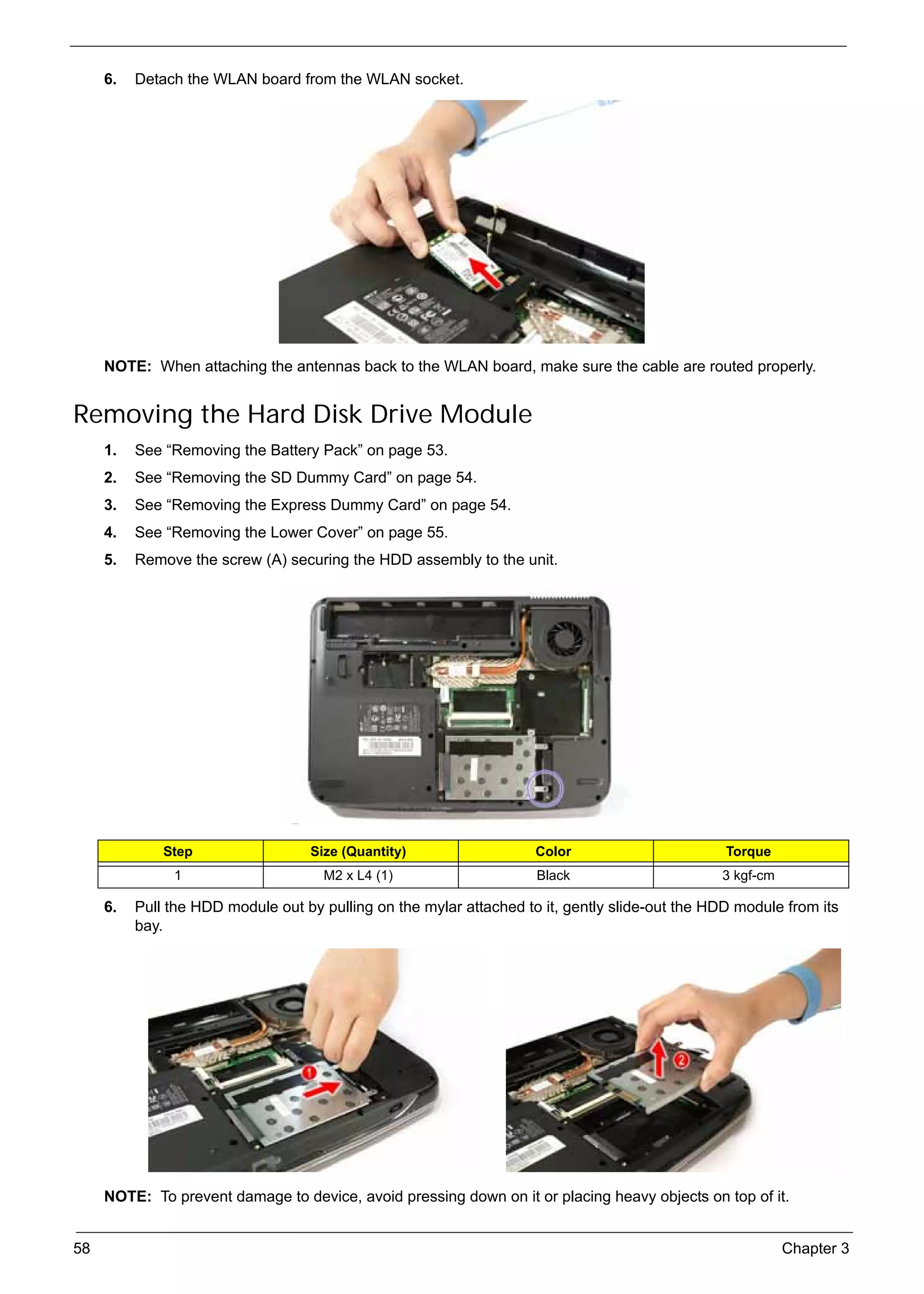
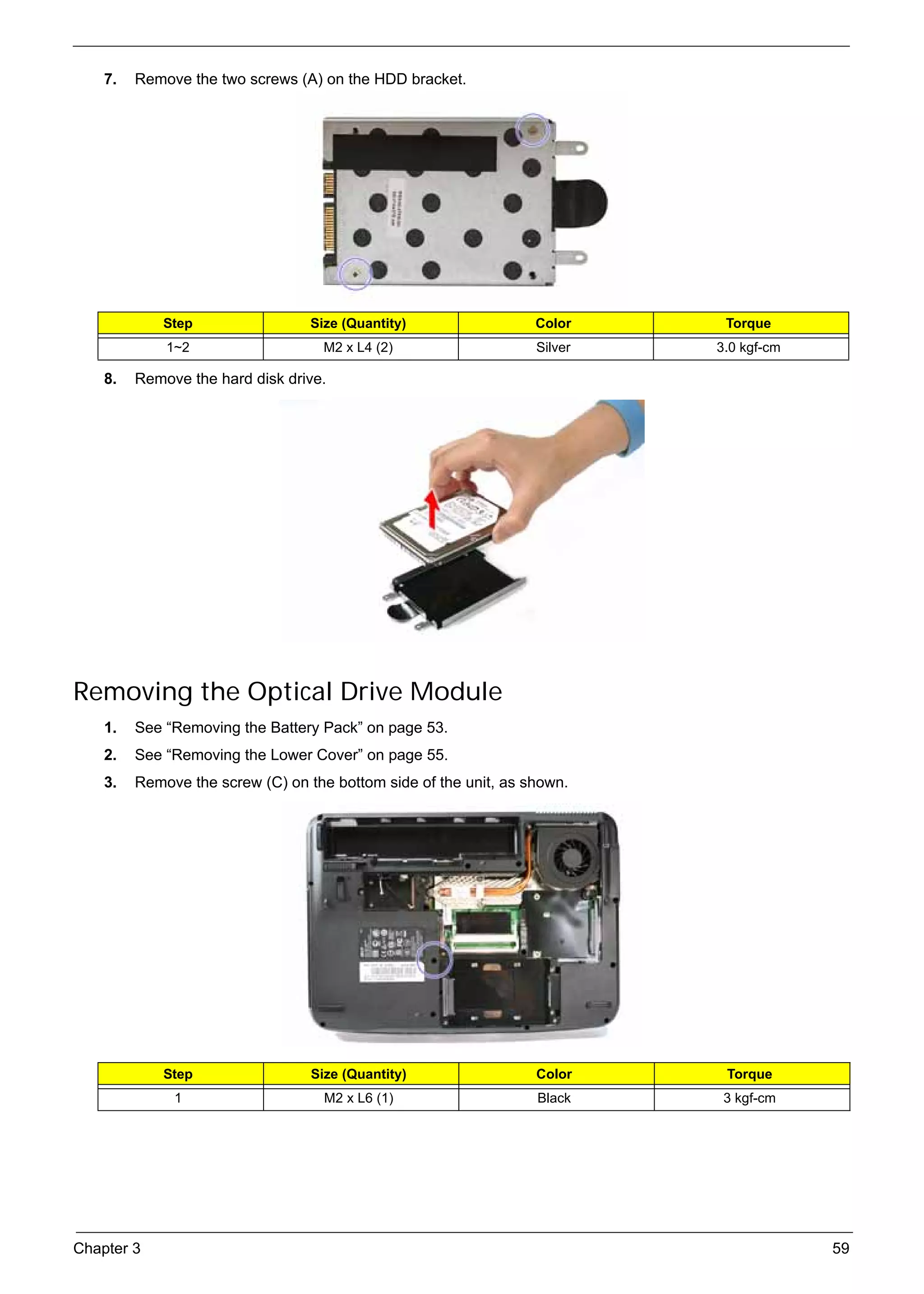
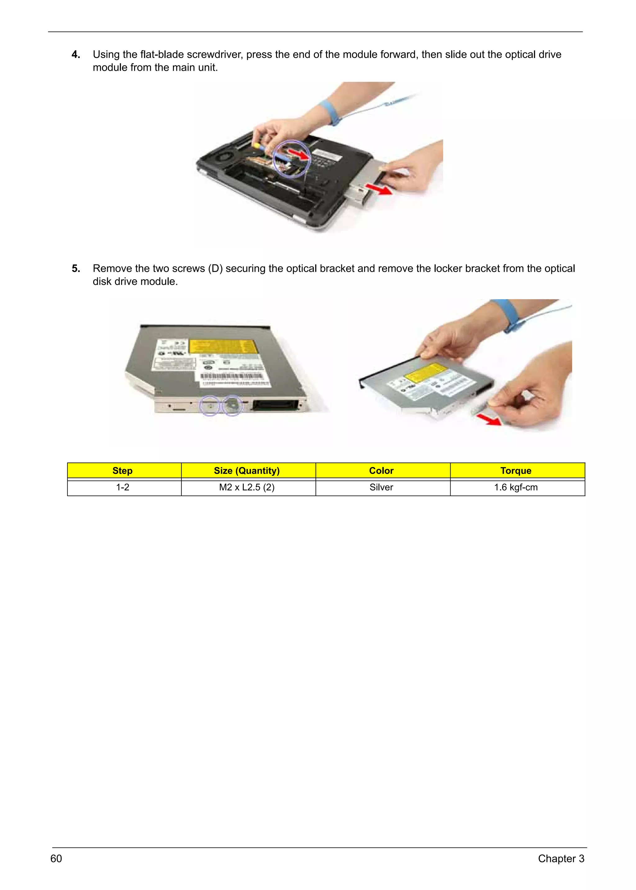
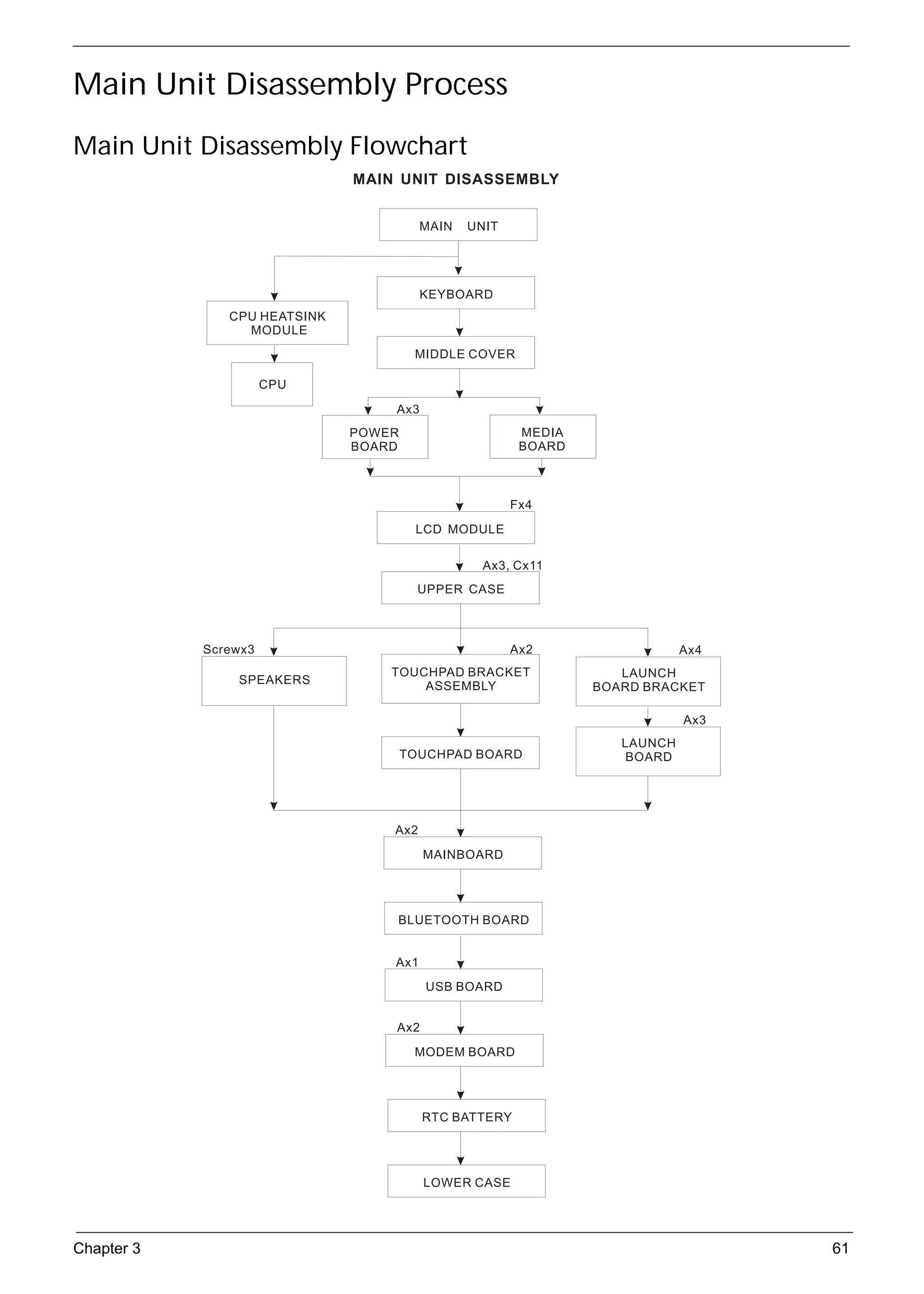
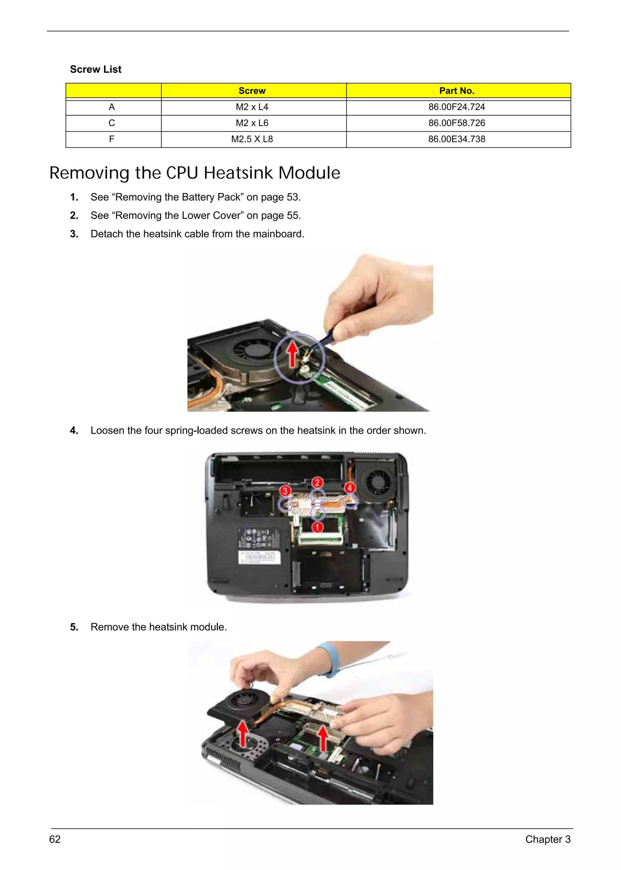
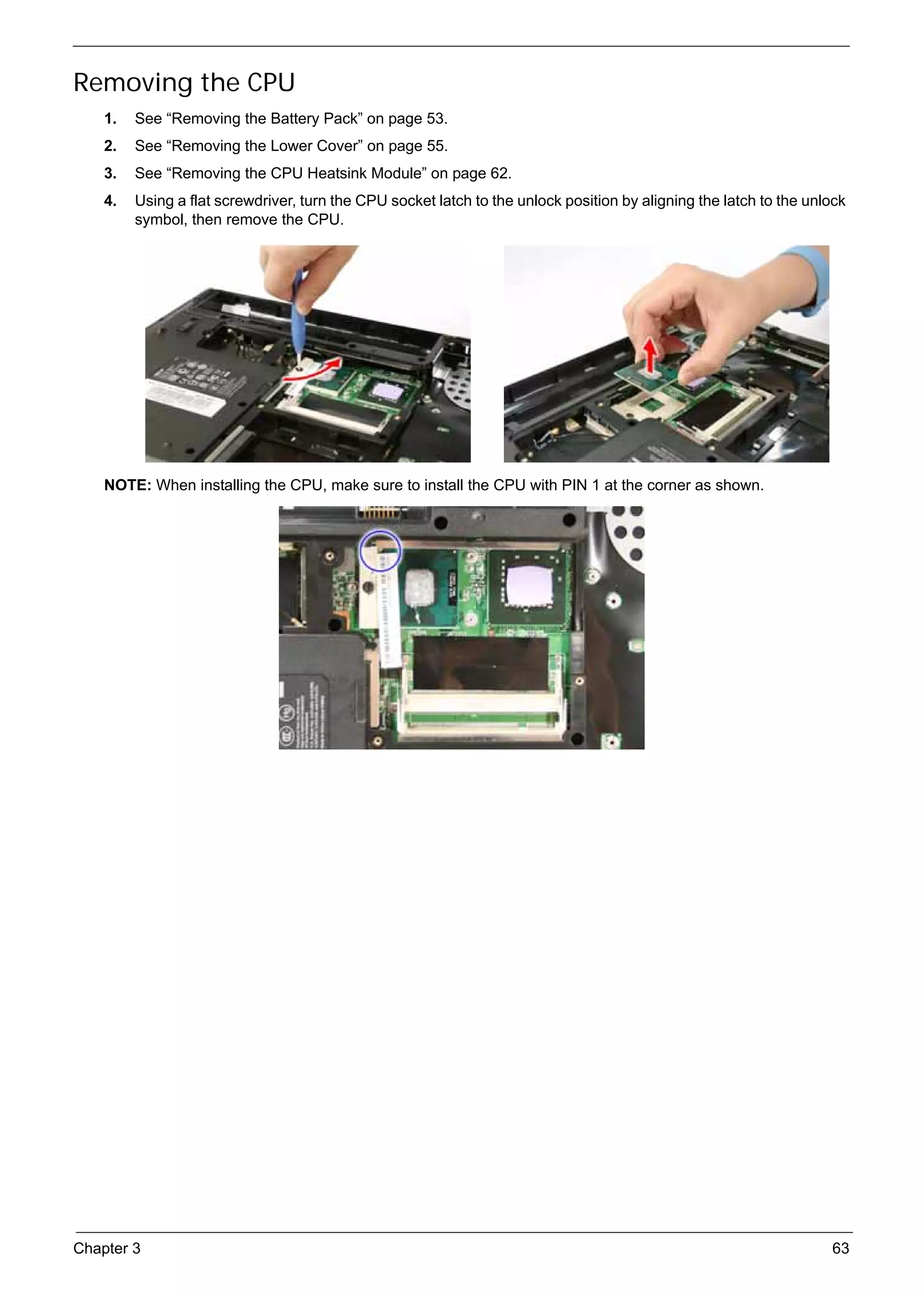
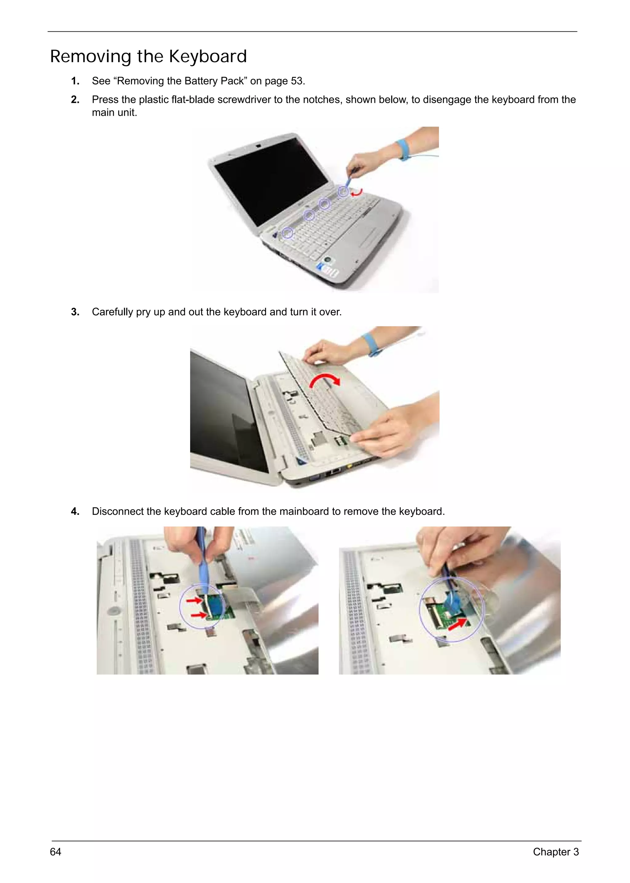
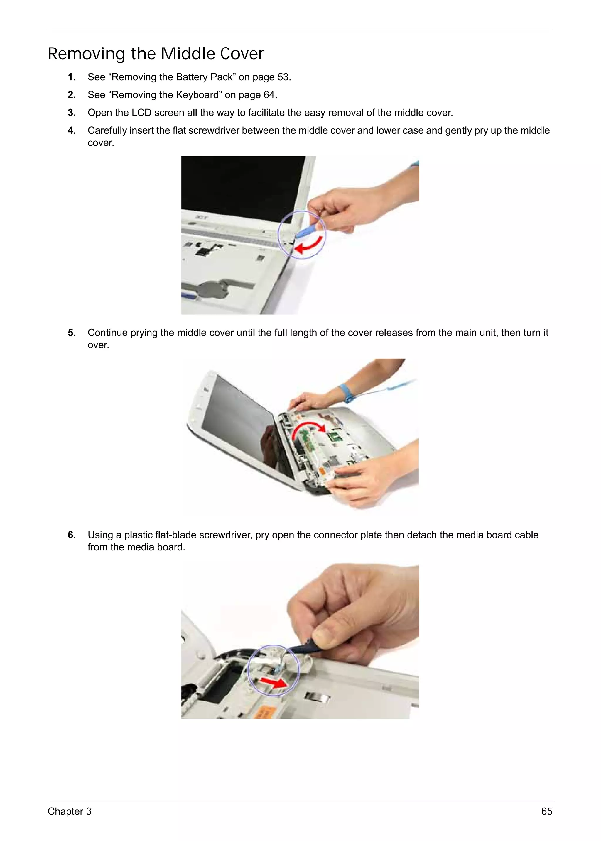
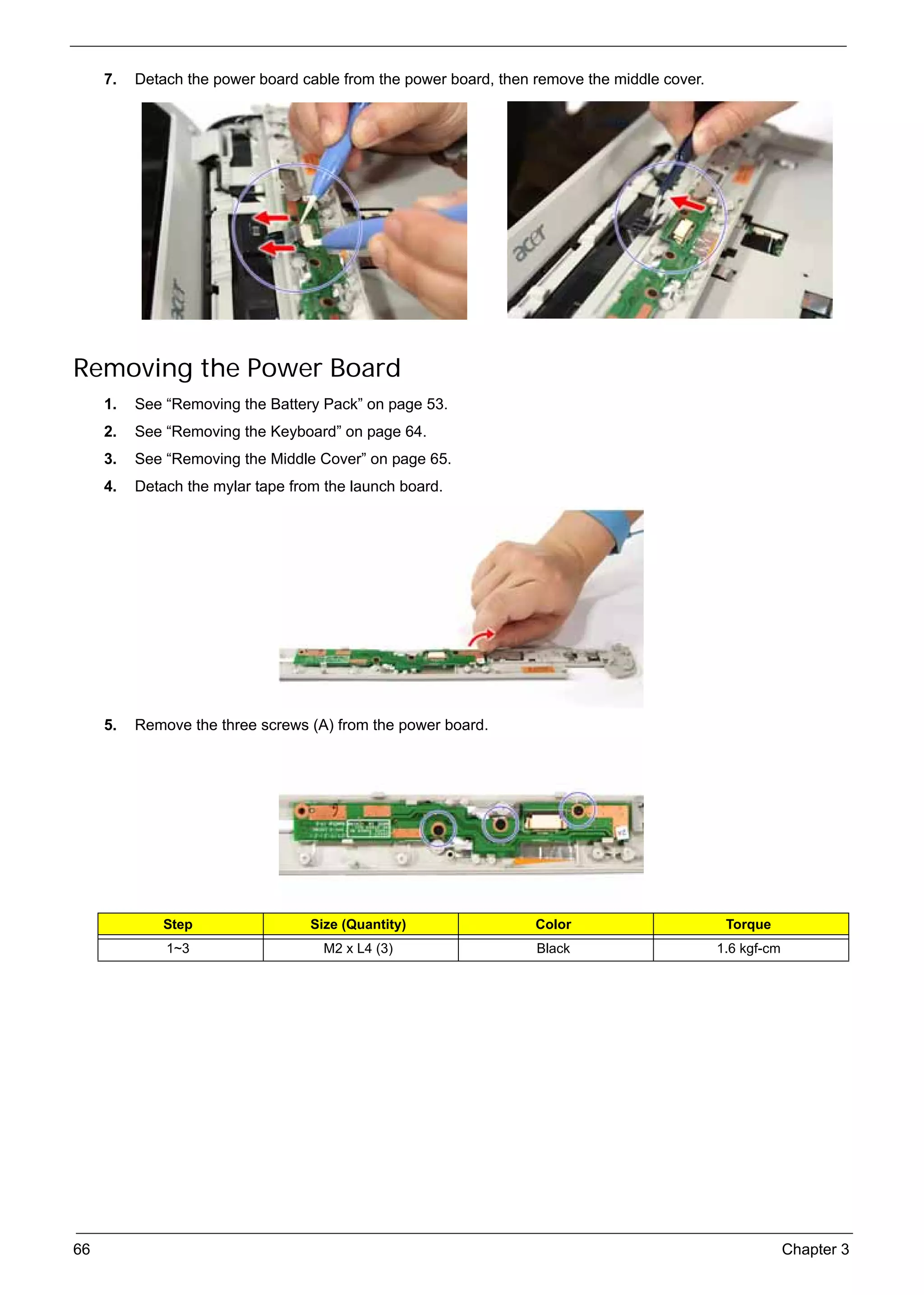
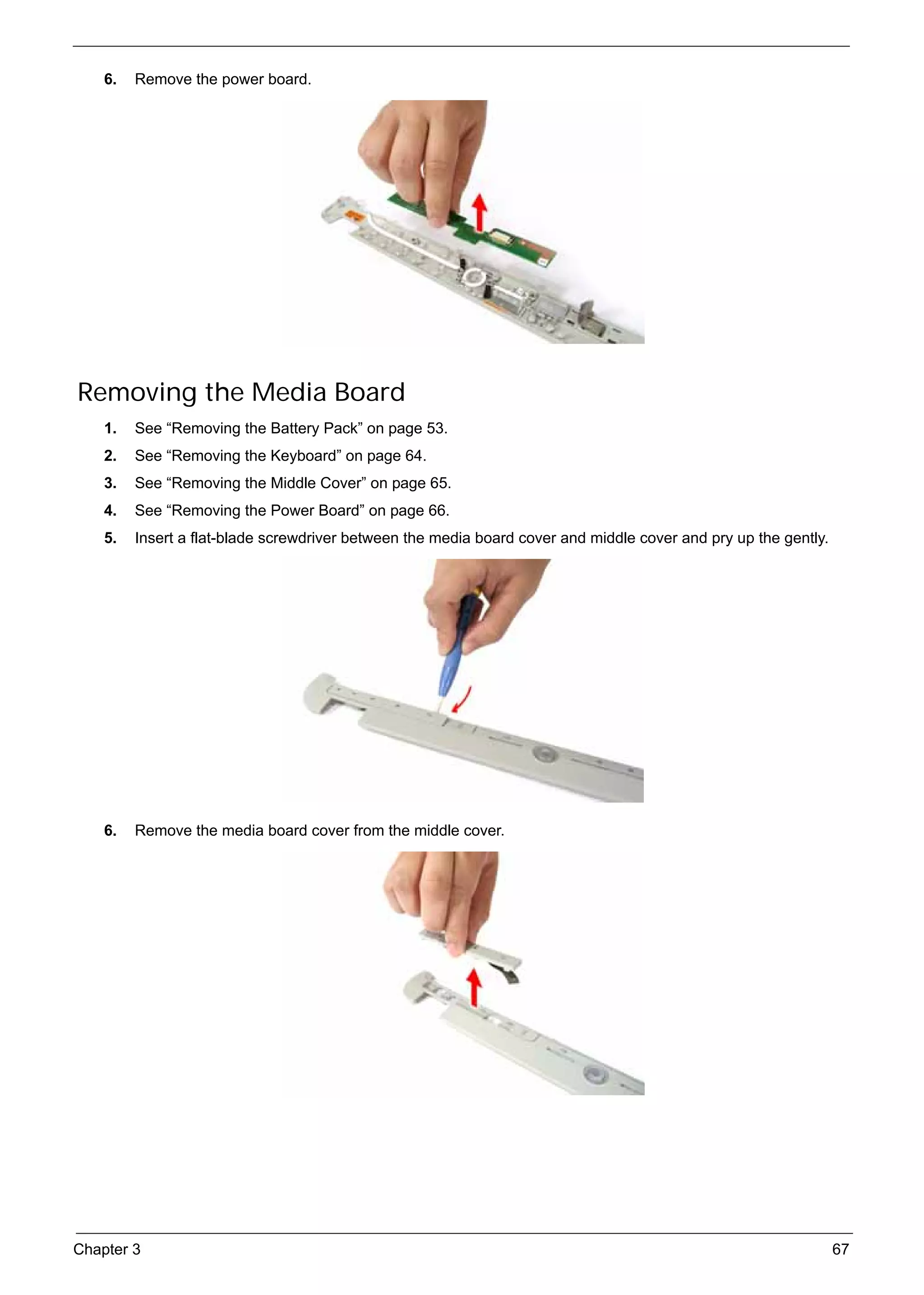
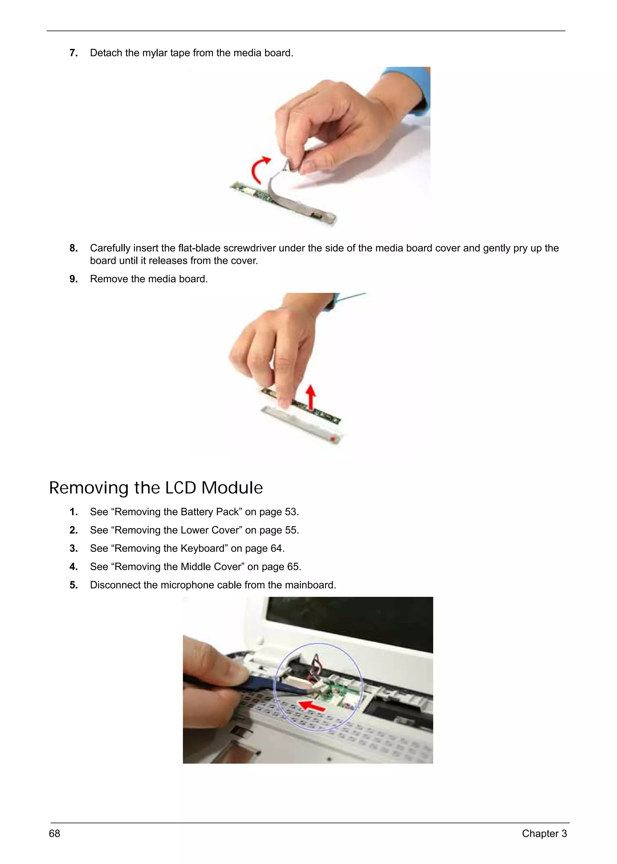
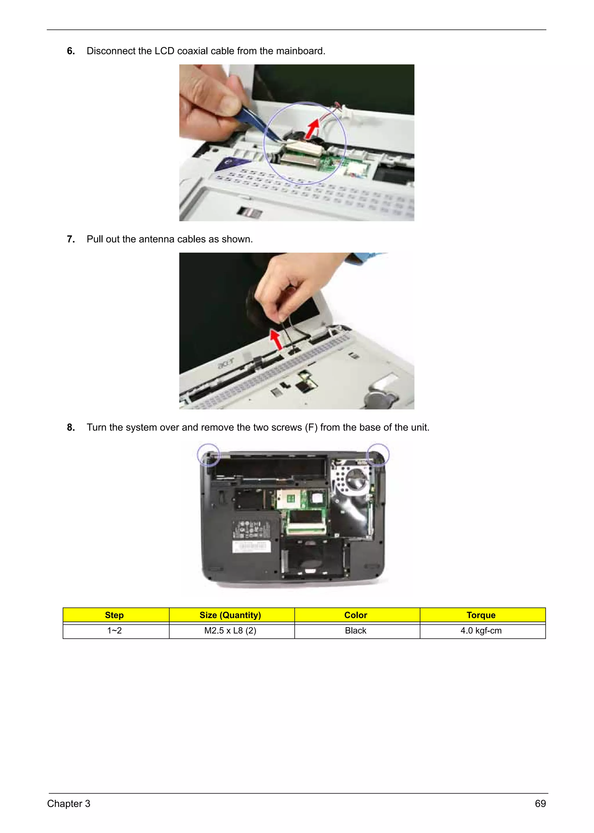
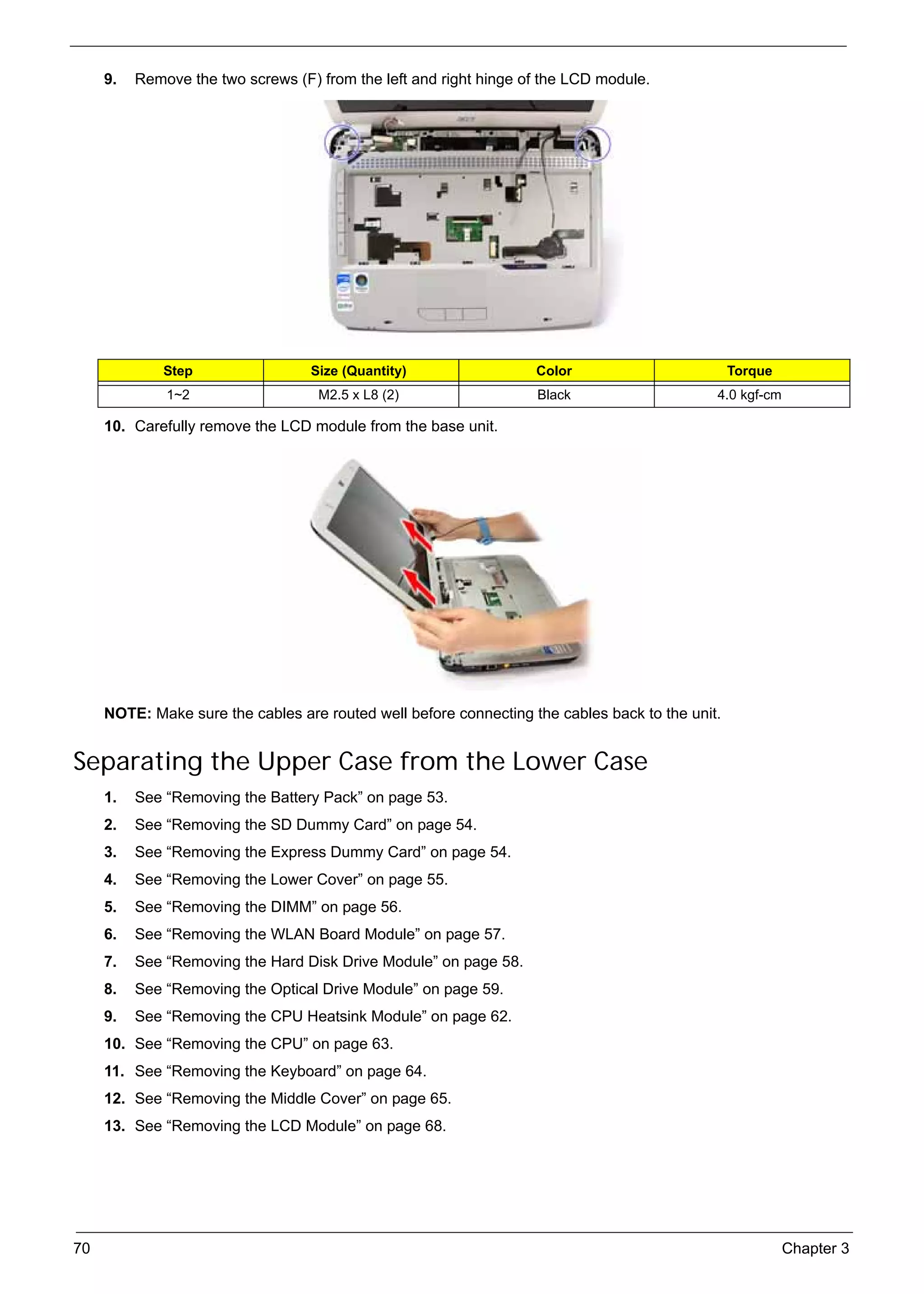
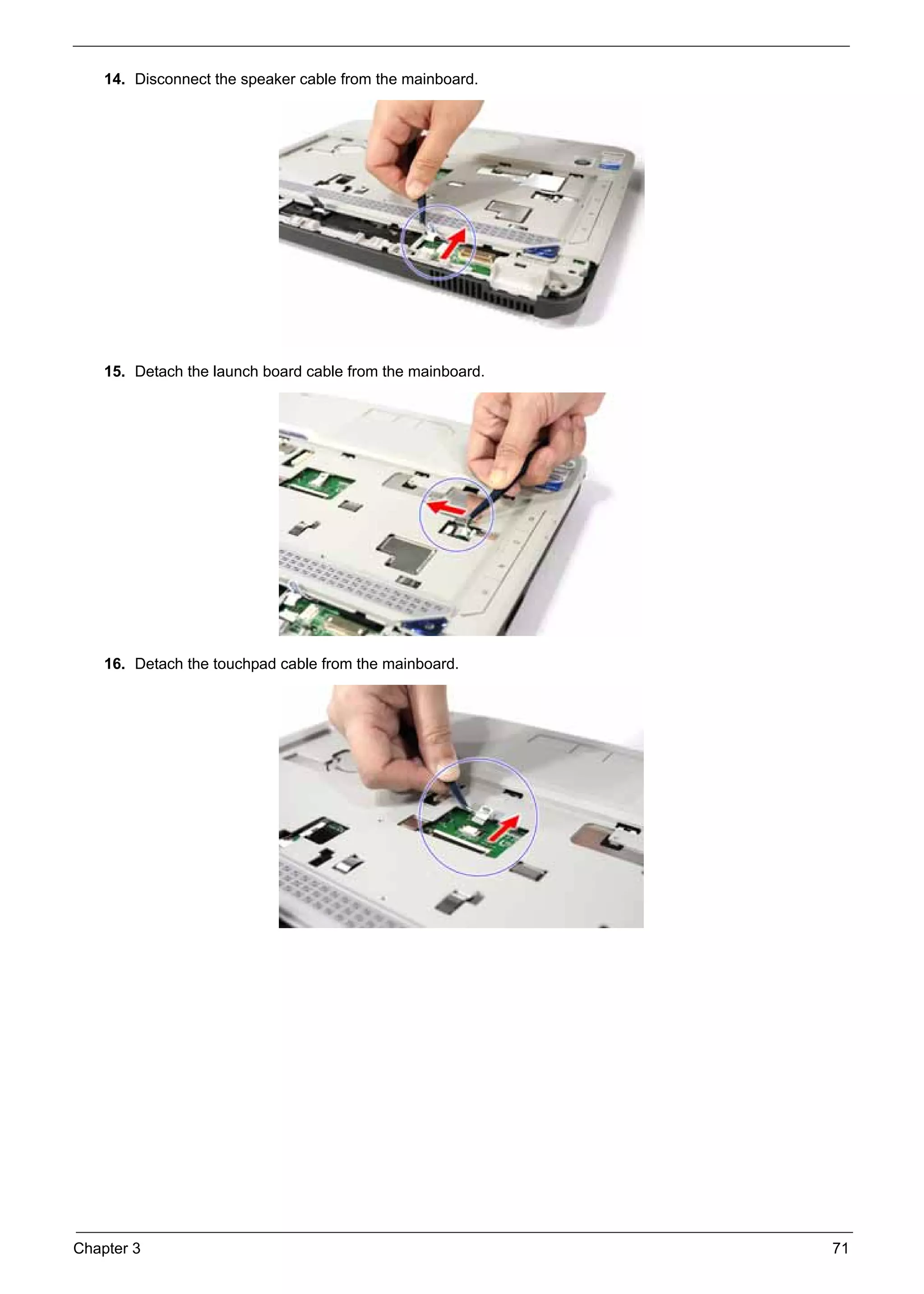
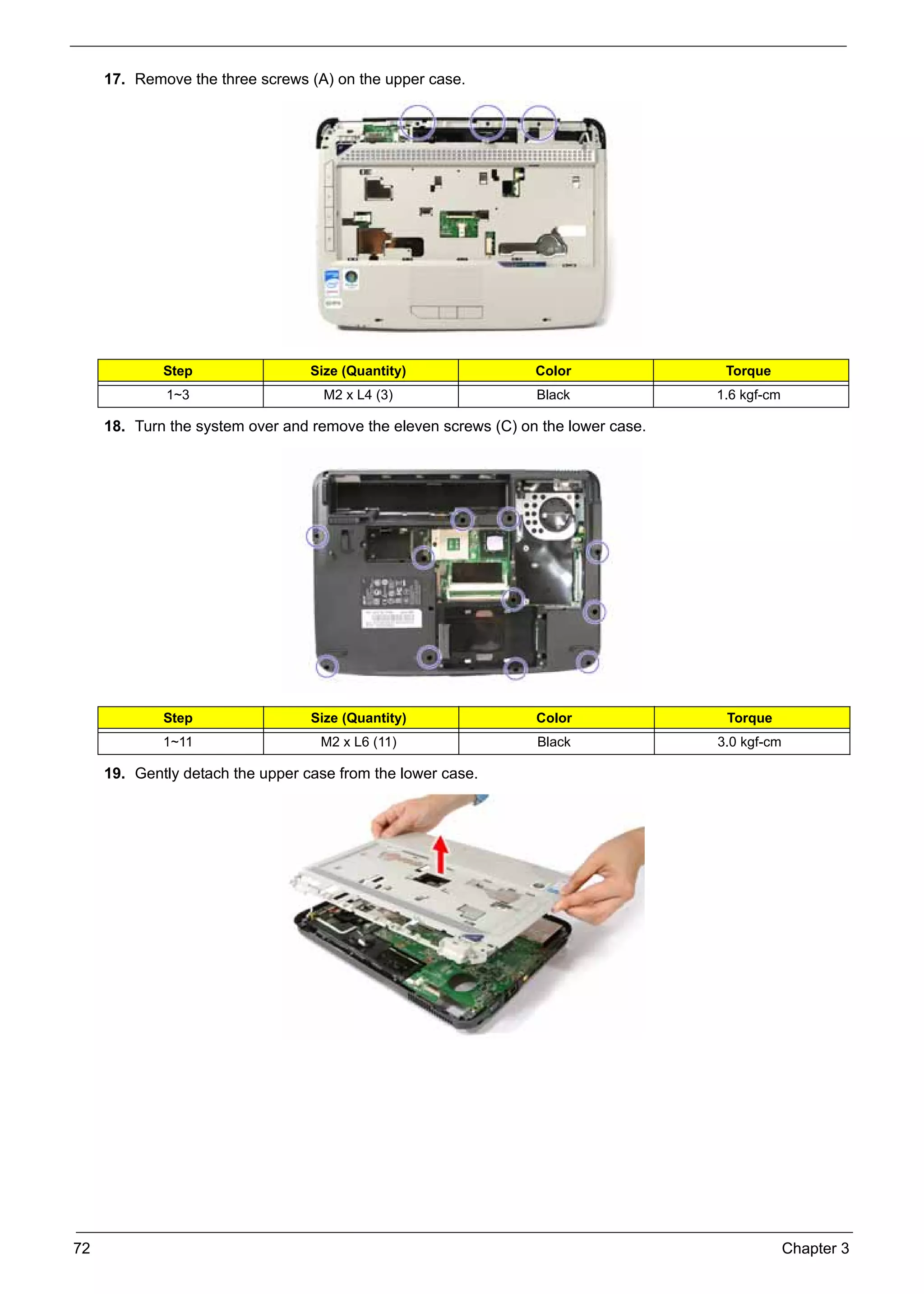
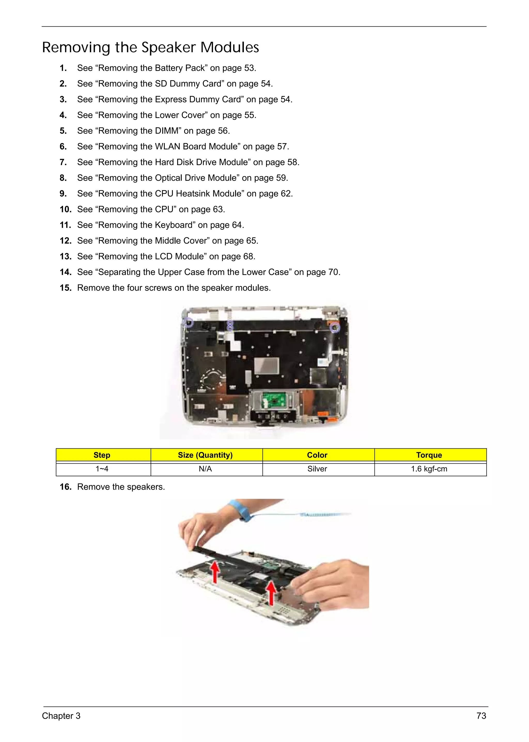
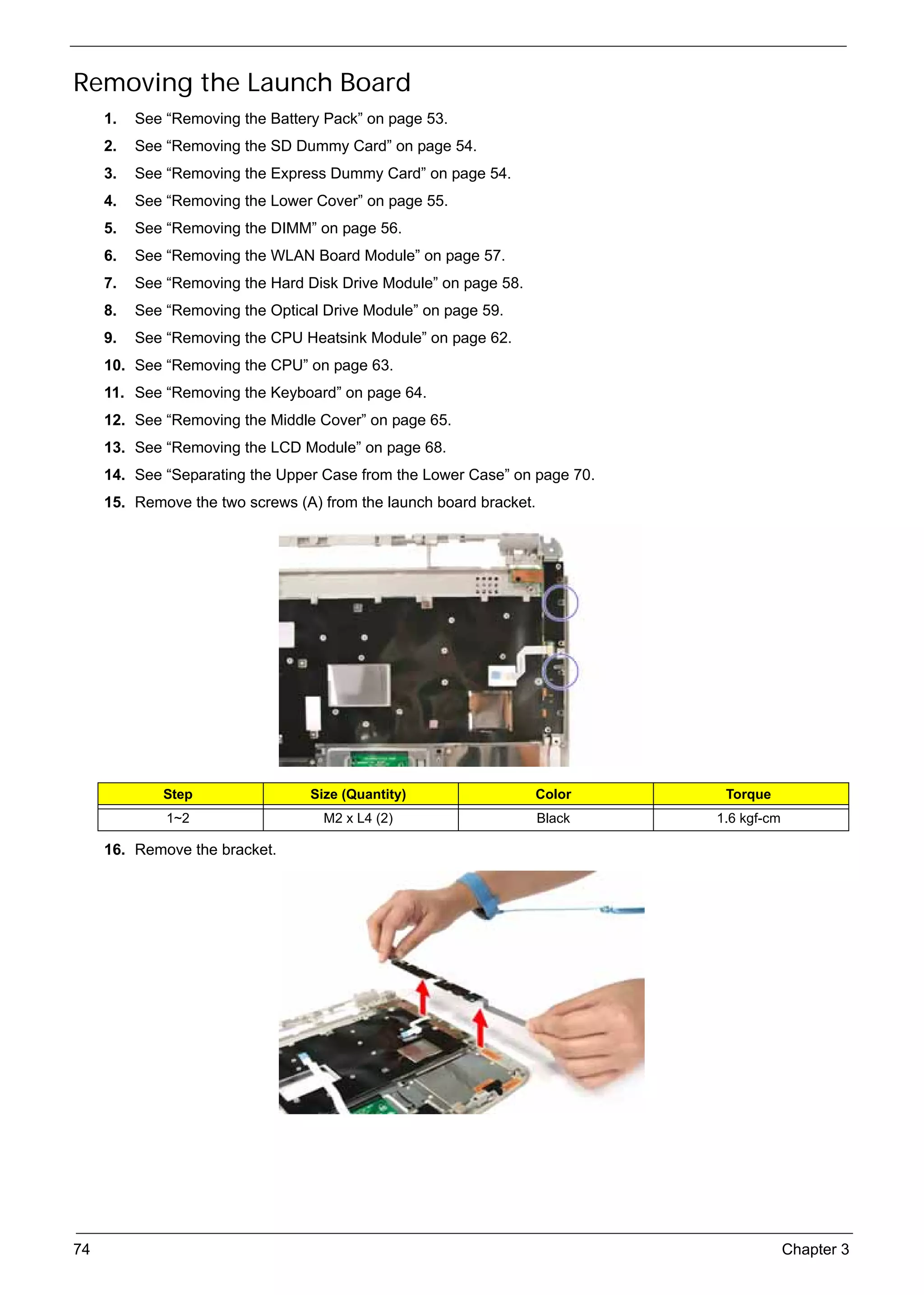
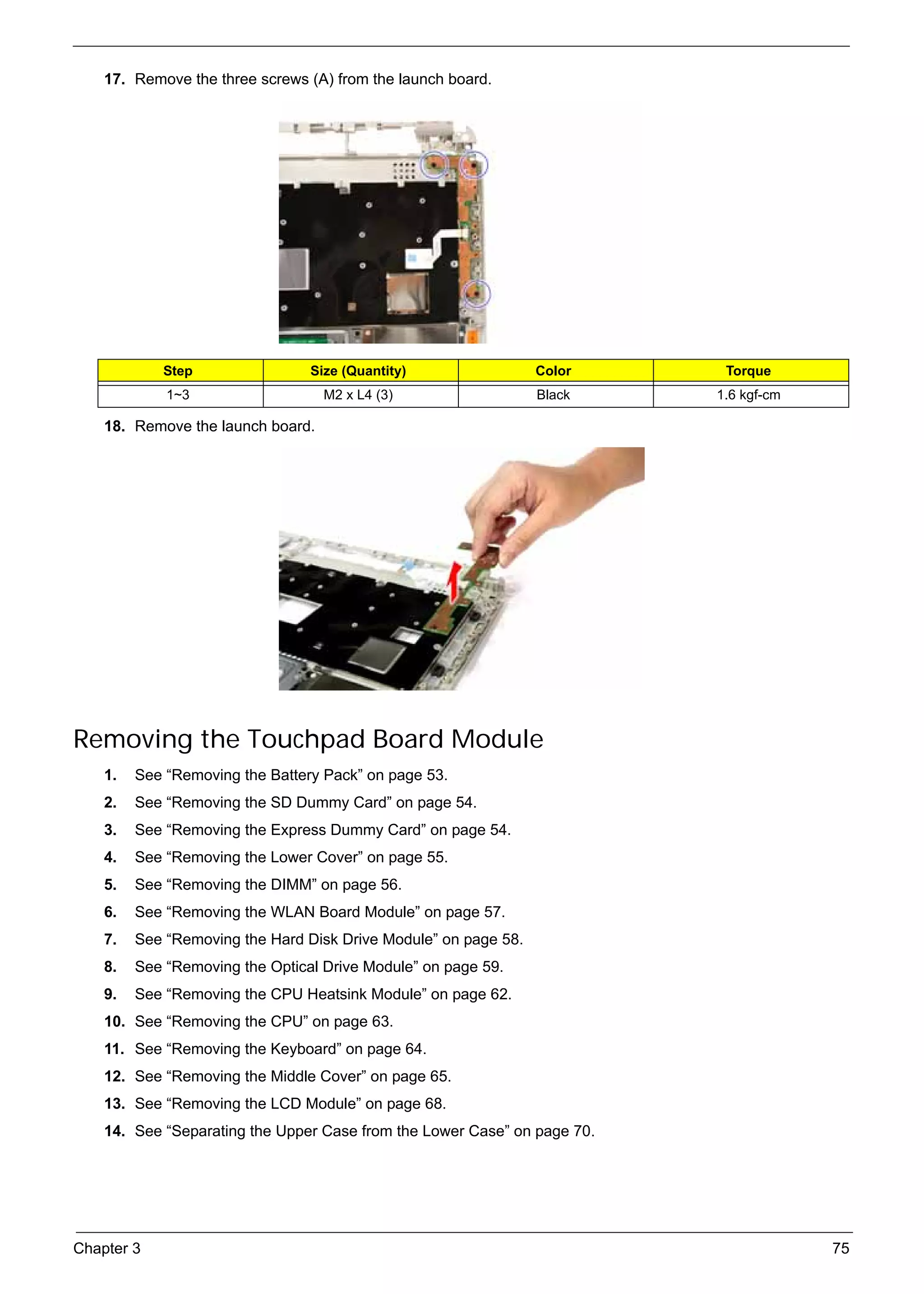
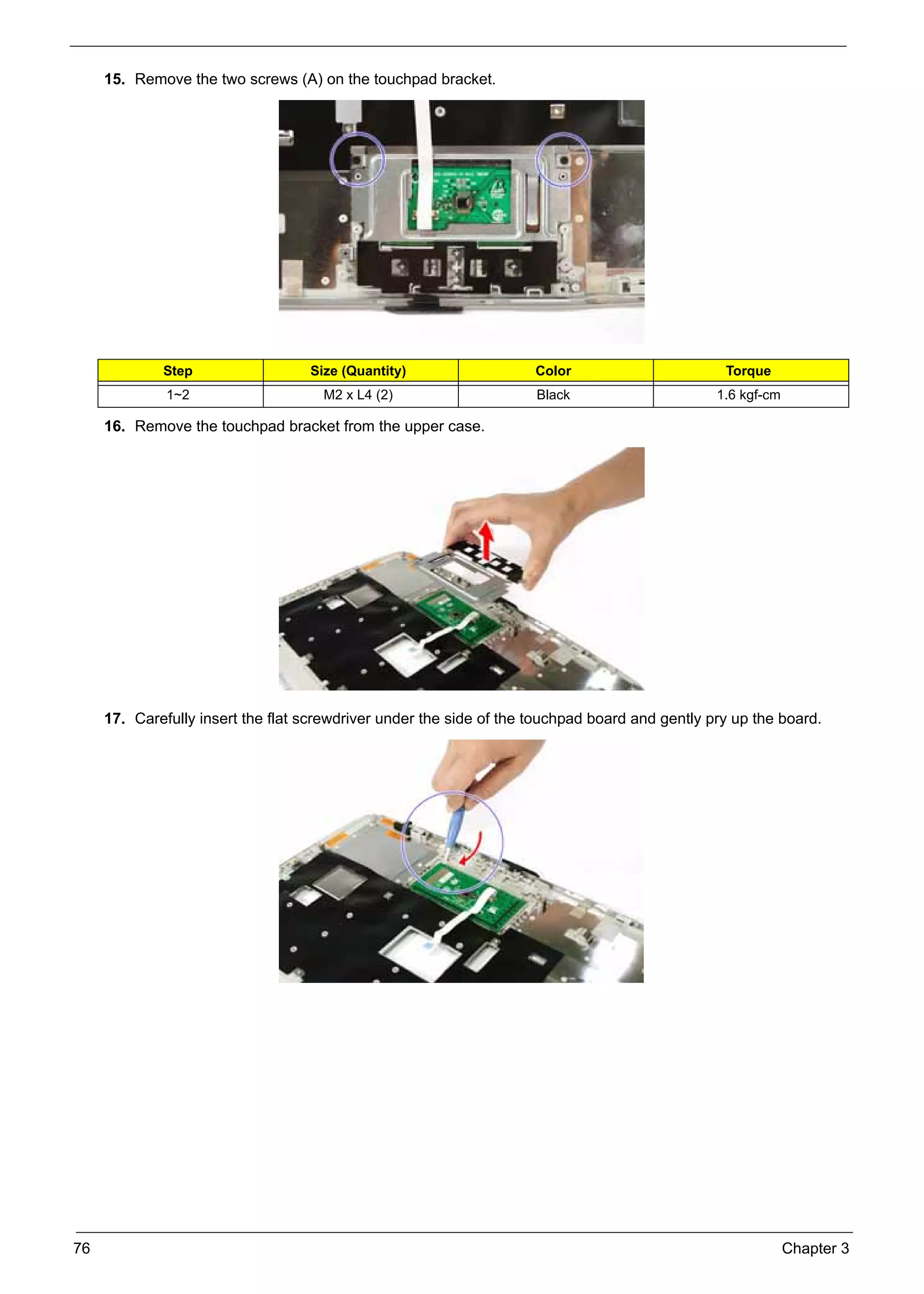
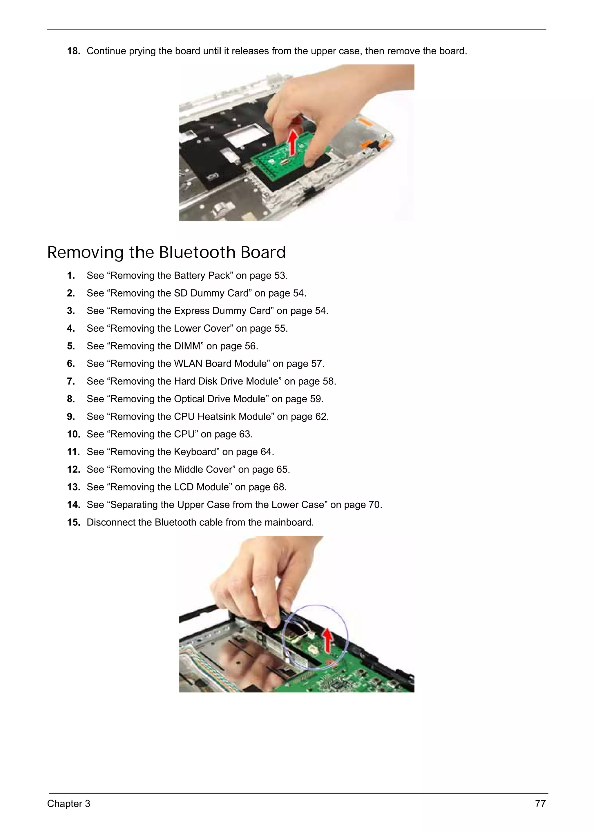
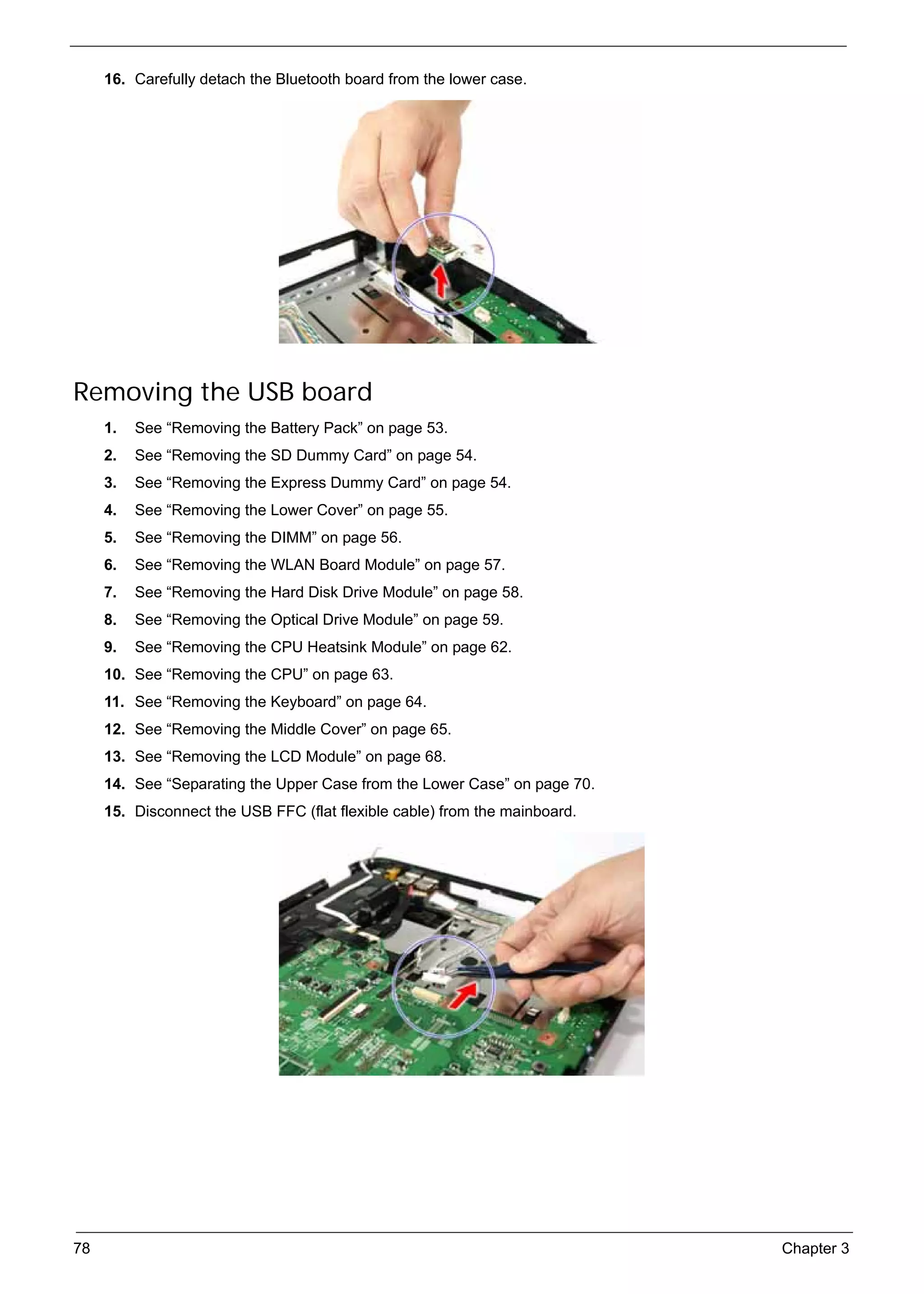
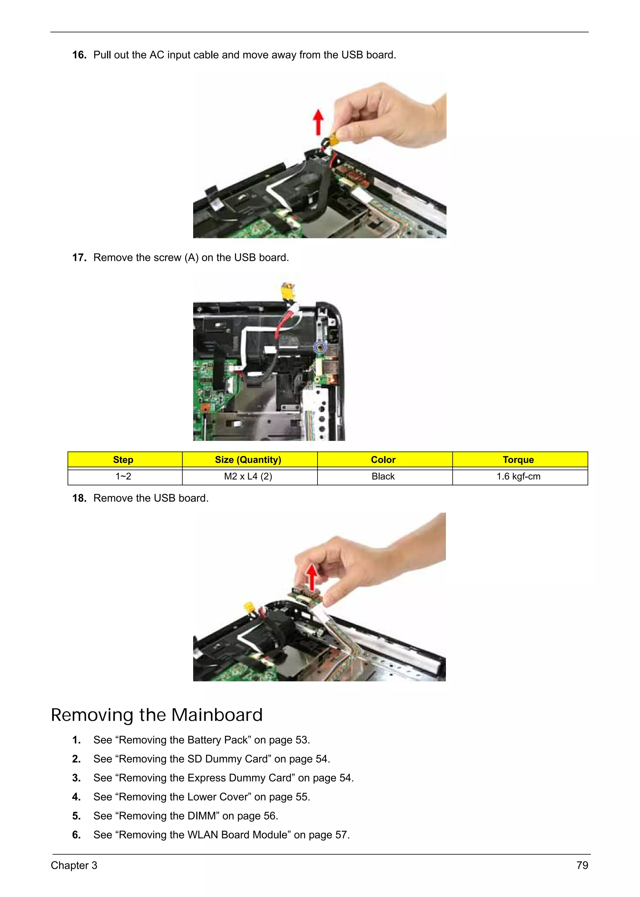
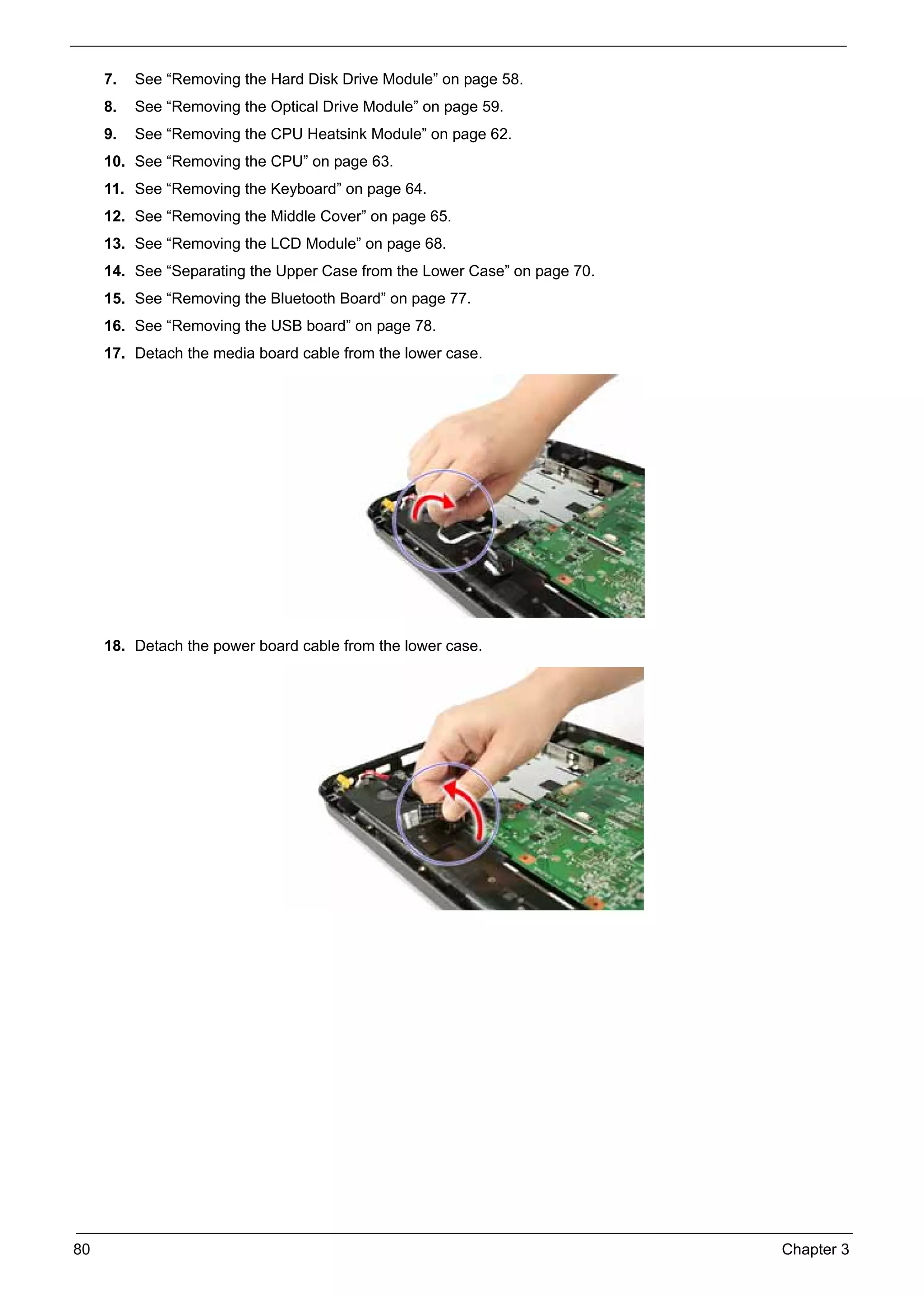
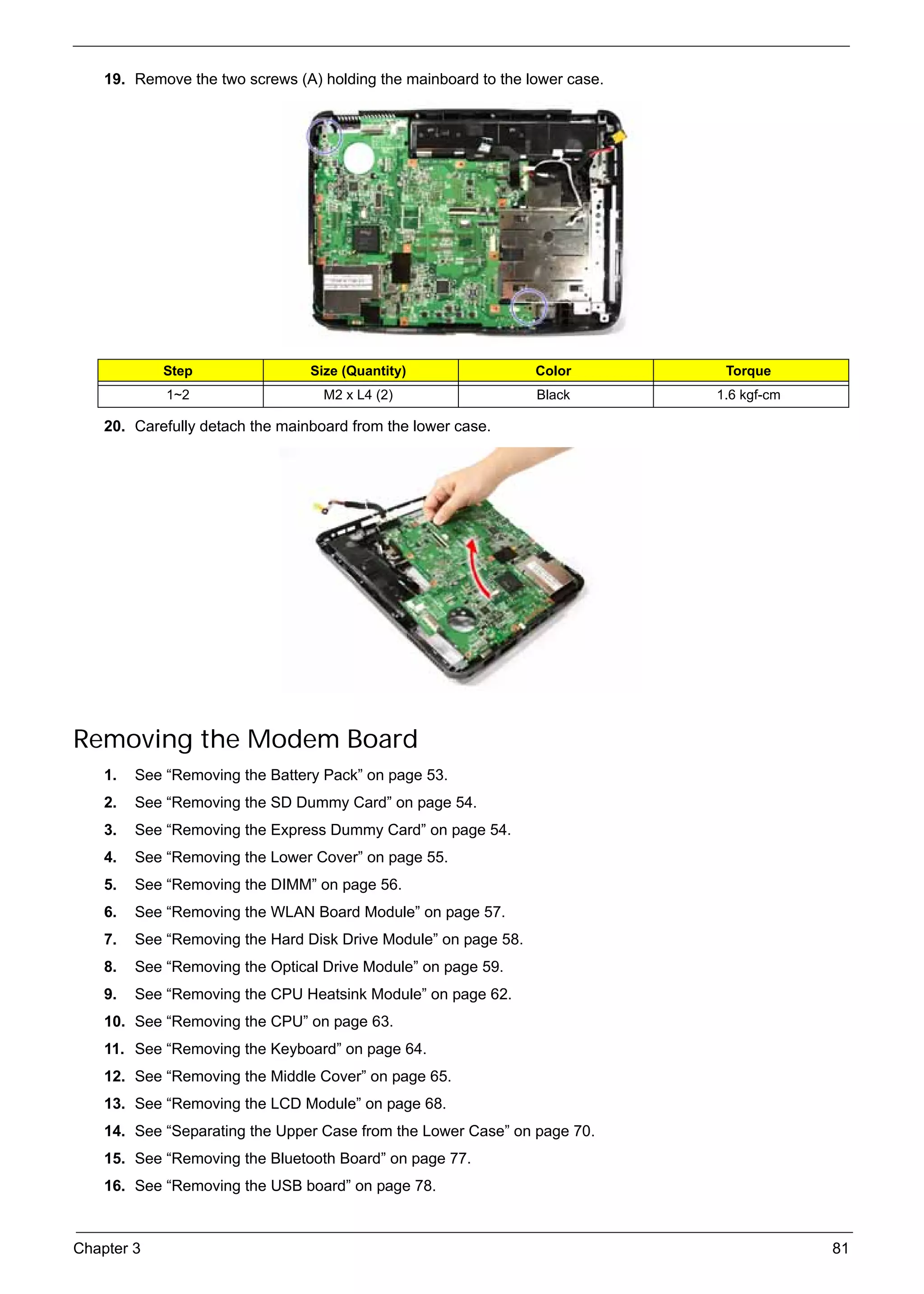
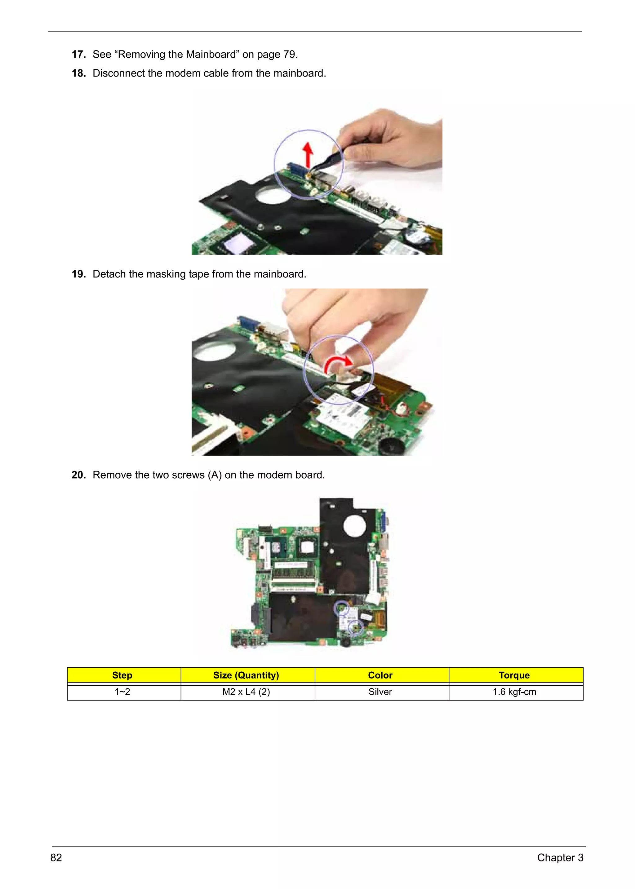
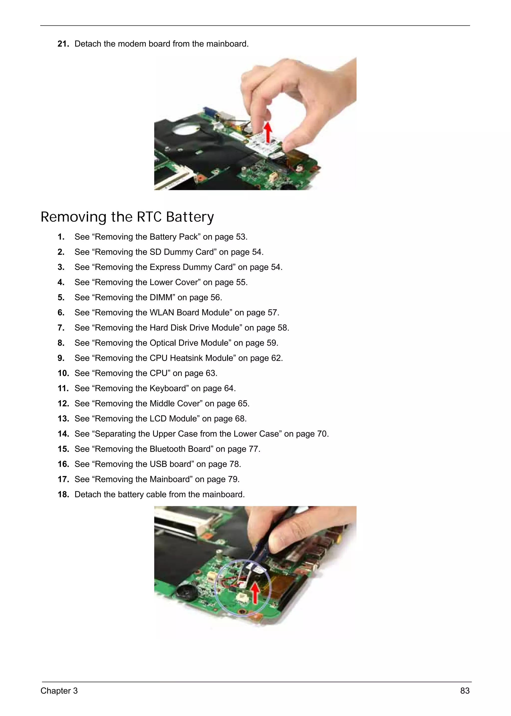
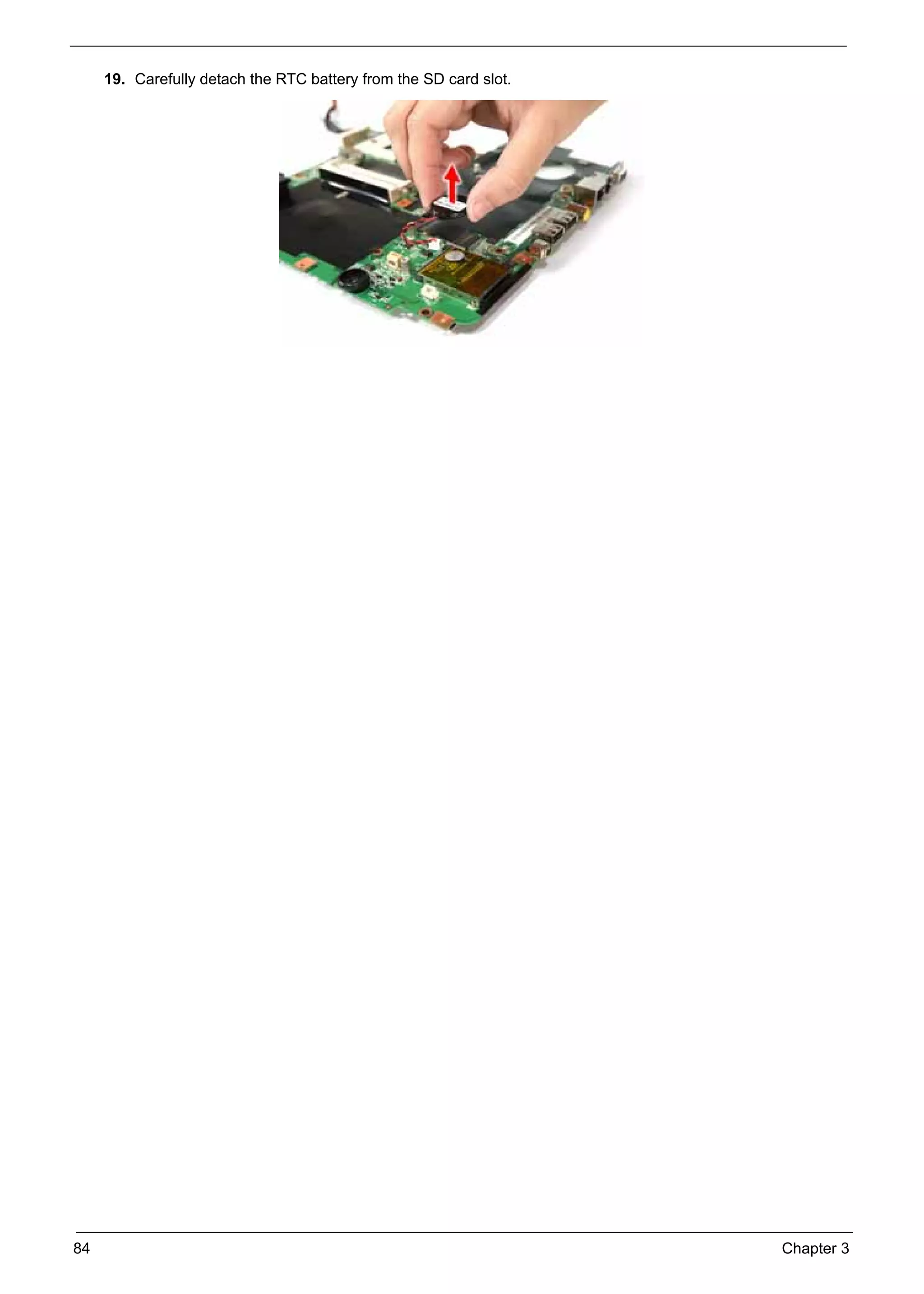
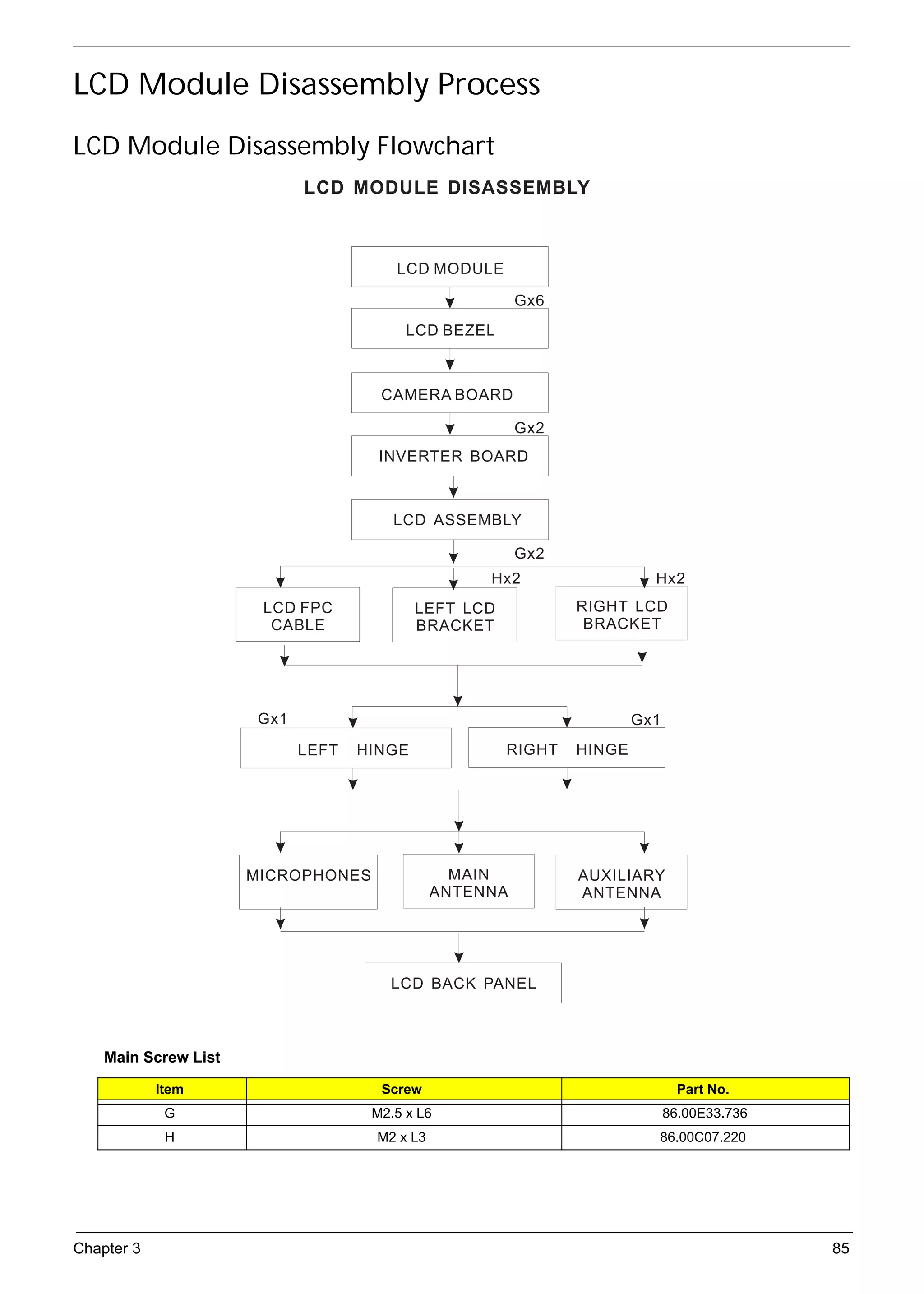
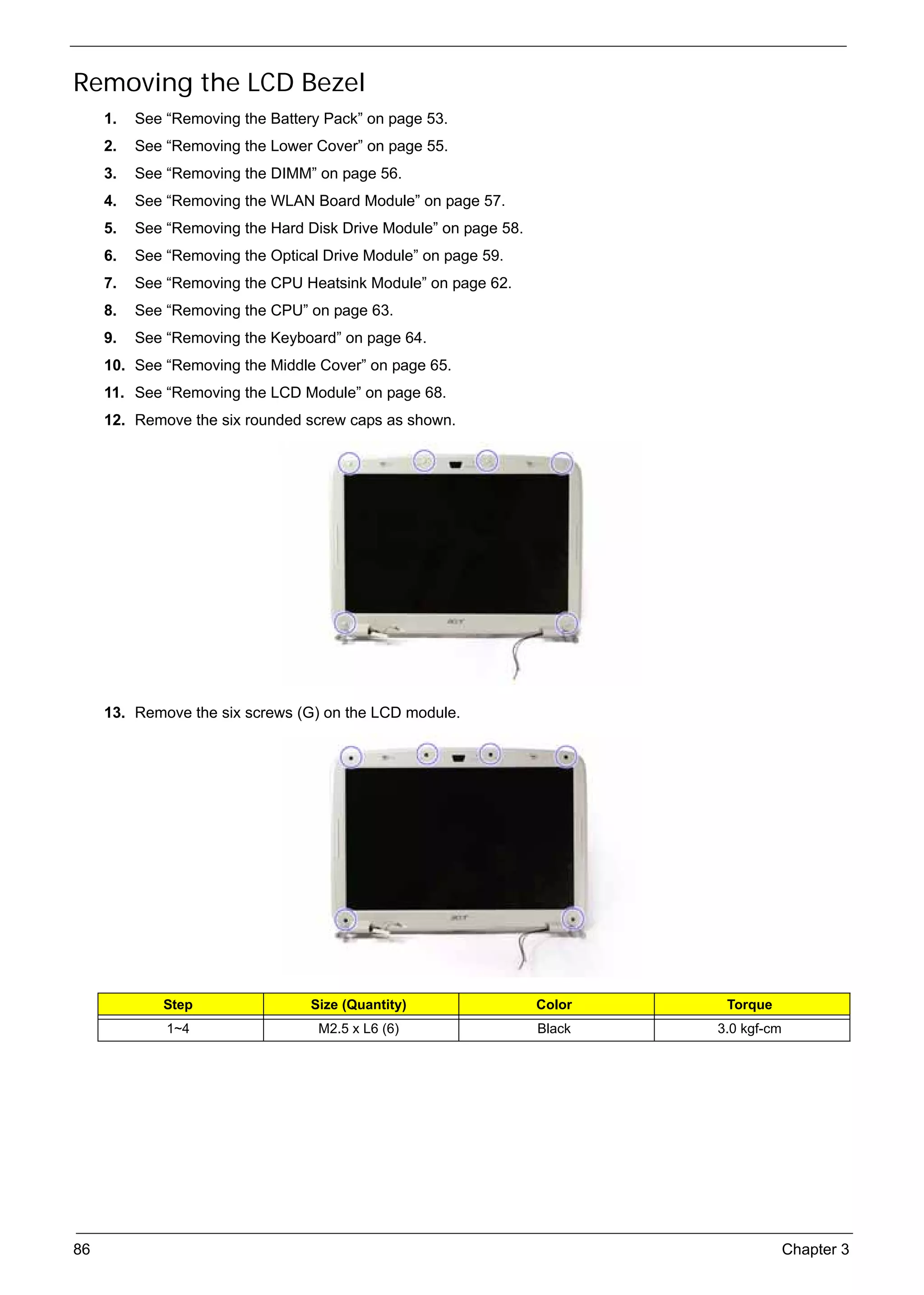
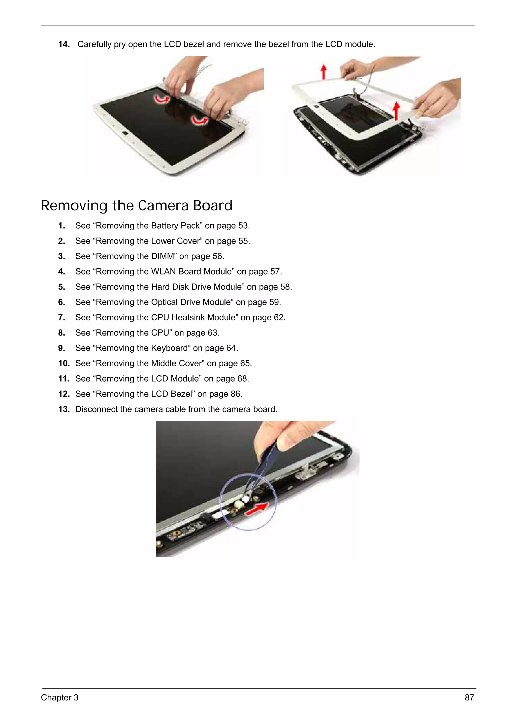
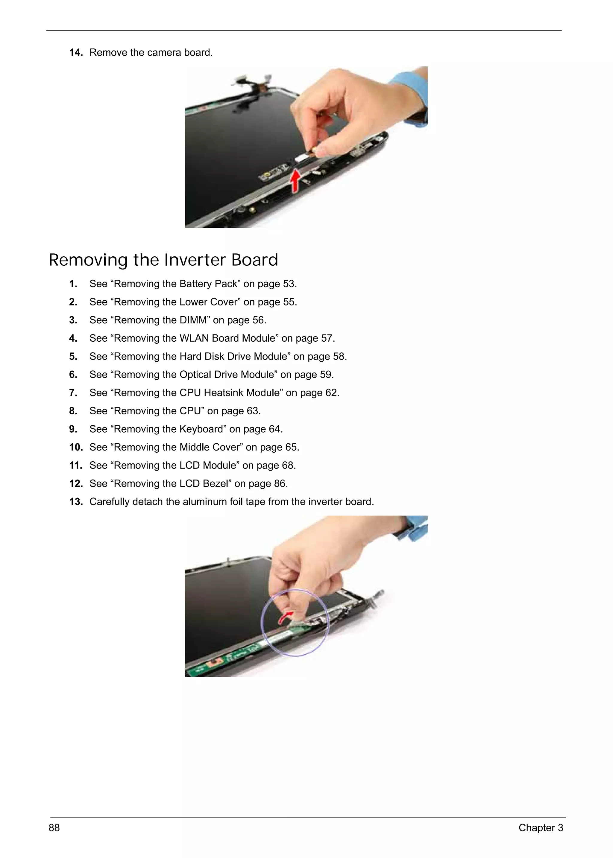
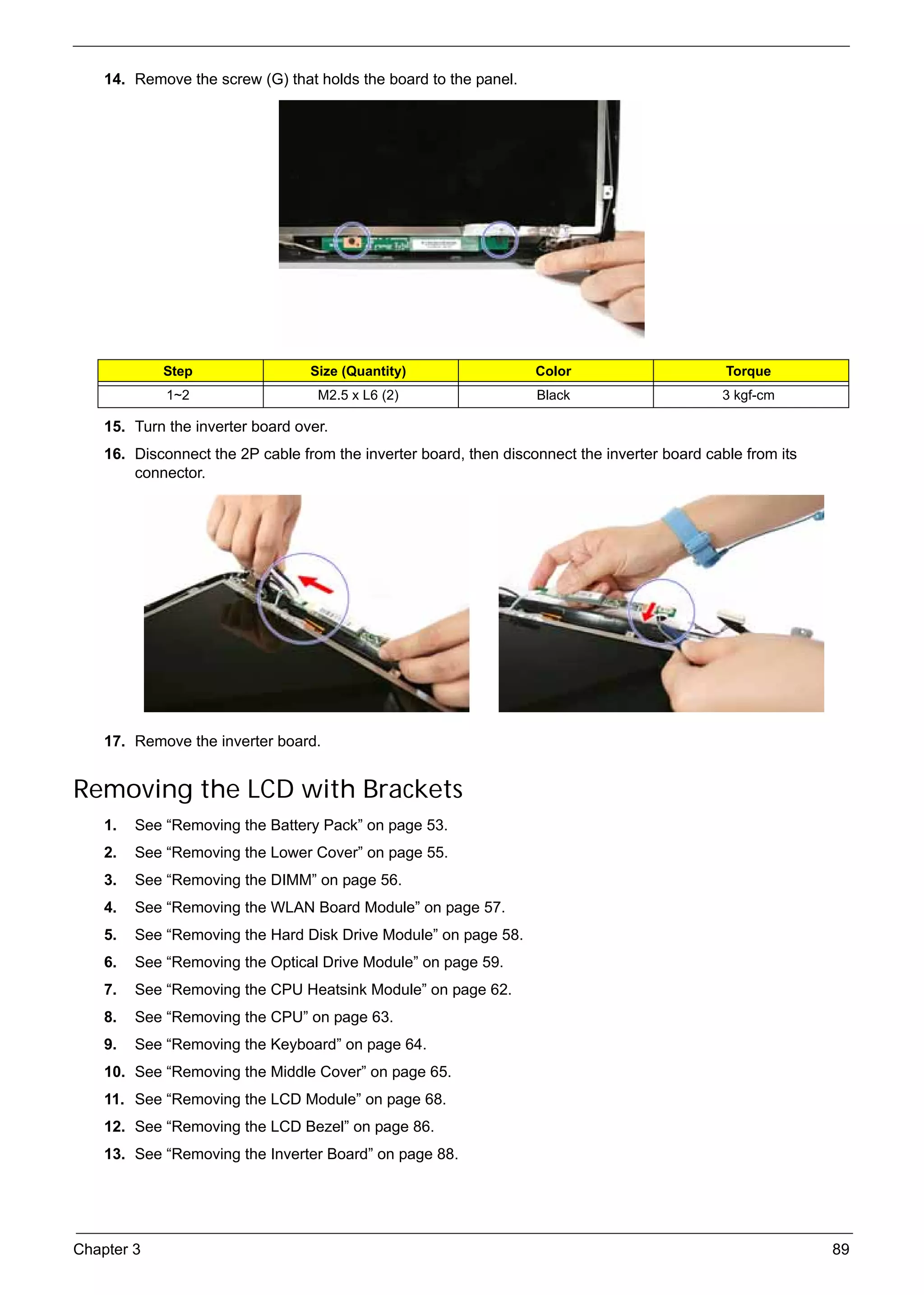
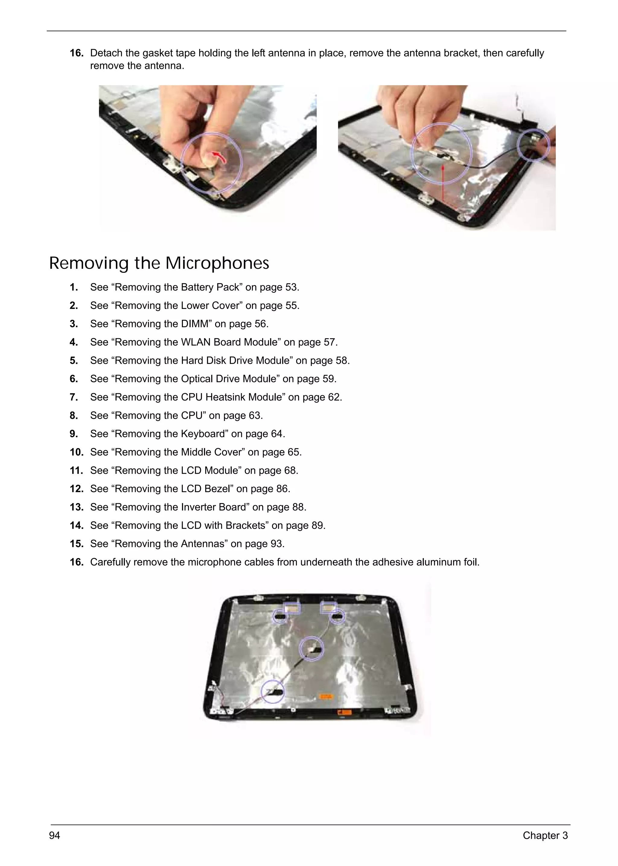
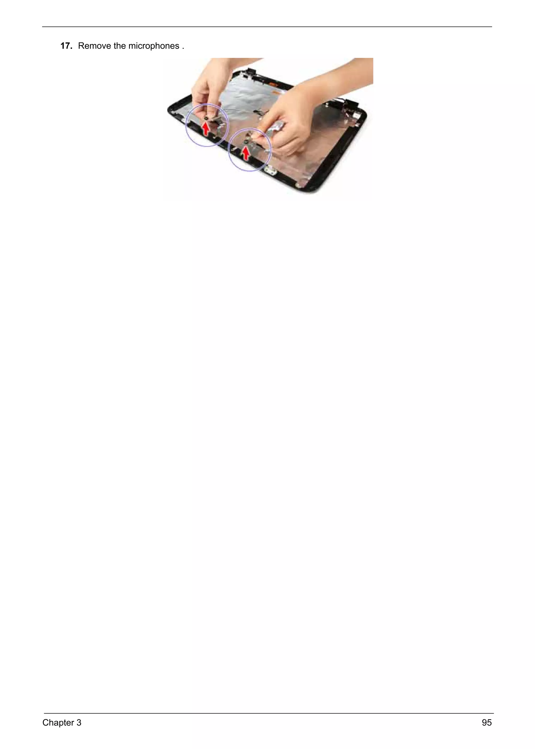
SG_Aspire4920_Book.book   Page i   Monday, May 28, 2007   6:49 PM


                                                                    Acer

                                                       Aspire 4920
                                                      Service Guide


                                                Service guide files and updates are available
                                                on the ACER/CSD web; for more information,
                                                    please refer to http://csd.acer.com.tw


                                                                                                PRINTED IN TAIWAN
SG_Aspire4920_Book.book   Page ii   Monday, May 28, 2007   6:49 PM


     Revision History
          Please refer to the table below for the updates made on Aspire 4920 service guide.


                    Date                          Chapter                           Updates


     ii
SG_Aspire4920_Book.book   Page iii   Monday, May 28, 2007 6:49 PM


     Copyright
          Copyright © 2007 by Acer Incorporated. All rights reserved. No part of this publication may be reproduced,
          transmitted, transcribed, stored in a retrieval system, or translated into any language or computer language, in
          any form or by any means, electronic, mechanical, magnetic, optical, chemical, manual or otherwise, without
          the prior written permission of Acer Incorporated.


                                                                                                                         iii
SG_Aspire4920_Book.book   Page iv   Monday, May 28, 2007   6:49 PM


     Disclaimer
          The information in this guide is subject to change without notice.
          Acer Incorporated makes no representations or warranties, either expressed or implied, with respect to the
          contents hereof and specifically disclaims any warranties of merchantability or fitness for any particular
          purpose. Any Acer Incorporated software described in this manual is sold or licensed "as is". Should the
          programs prove defective following their purchase, the buyer (and not Acer Incorporated, its distributor, or its
          dealer) assumes the entire cost of all necessary servicing, repair, and any incidental or consequential
          damages resulting from any defect in the software.


          Acer is a registered trademark of Acer Corporation.
          Intel is a registered trademark of Intel Corporation.
          Core Duo and Core 2 Duo are trademarks of Intel Corporation.
          Other brand and product names are trademarks and/or registered trademarks of their respective holders.


     iv
SG_Aspire4920_Book.book   Page v   Monday, May 28, 2007   6:49 PM


     Conventions
          The following conventions are used in this manual:

               SCREEN                            Denotes actual messages that appear on screen.
               MESSAGES
               NOTE                              Gives bits and pieces of additional information related to the current topic.


               WARNING                           Alerts you to any damage that might result from doing or not doing specific
                                                 actions.
               CAUTION                           Gives precautionary measures to avoid possible hardware or software
                                                 problems.
               IMPORTANT                         Reminds you to do specific actions relevant to the accomplishment of
                                                 procedures.


                                                                                                                                 v
SG_Aspire4920_Book.book   Page vi   Monday, May 28, 2007   6:49 PM


     Preface
          Before using this information and the product it supports, please read the following general information.
          1.   This Service Guide provides you with all technical information relating to the BASIC CONFIGURATION
               decided for Acer's "global" product offering. To better fit local market requirements and enhance product
               competitiveness, your regional office MAY have decided to extend the functionality of a machine (e.g.
               add-on card, modem, or extra memory capability). These LOCALIZED FEATURES will NOT be covered
               in this generic service guide. In such cases, please contact your regional offices or the responsible
               personnel/channel to provide you with further technical details.
          2.   Please note WHEN ORDERING FRU PARTS, that you should check the most up-to-date information
               available on your regional web or channel. If, for whatever reason, a part number change is made, it will
               not be noted in the printed Service Guide. For ACER-AUTHORIZED SERVICE PROVIDERS, your Acer
               office may have a DIFFERENT part number code to those given in the FRU list of this printed Service
               Guide. You MUST use the list provided by your regional Acer office to order FRU parts for repair and
               service of customer machines.


     vi
SG_Aspire4920_Book.book   Page vii   Monday, May 28, 2007 6:49 PM


     Table of Contents
     System Specification                                            1
                   Features                                          1
                   Your Acer Notebook Tour                           4
                        Front View                                   4
                        Closed Front View                            5
                        Left View                                    6
                        Right View                                   7
                        Rear Panel                                   7
                        Bottom Panel                                 8
                   Indicators                                        9
                   Easy-launch Buttons                              10
                   MediaTouch Keys                                  11
                   Touchpad                                         12
                        Touchpad Basics                             12
                   Using the Keyboard                               14
                        Lock Keys and Embedded Numeric Keypad       14
                        Windows Keys                                15
                        Hotkeys                                     16
                        Special Keys                                17
                   Acer Empowering Technology                       18
                        Empowering Technology Password              18
                        Acer eNet Management                        19
                        Acer ePower Management                      21
                        Acer eAudio Management                      23
                        Acer ePresentation Management               24
                        Acer eDataSecurity Management               25
                        Acer eLock Management                       26
                        Acer eRecovery Management                   27
                        Acer eSettings Management                   28
                        Windows Mobility Center                     29
                   Using the System Utilities                       30
                        Acer GridVista (dual-display compatible)    30
                        Launch Manager                              31
                        Norton Internet Security                    32
                   Hardware Specifications and Configurations       33
     System Utilities                                               41
                   BIOS Setup Utility                               41
                       Entering BIOS Setup                          41
                       BIOS Setup Primary Menus                     41
                       BIOS Setup Navigation Keys                   41
                       Information Menu                             42
                       Main Menu                                    43
                       Security Menu                                44
                       Boot Menu                                    46
                       Exit Menu                                    47
     Machine Disassembly and Replacement                            49
                   Disassembly Requirements                         49
                   General Information                              50
                       Pre-disassembly Instructions                 50
                       Disassembly Process                          51


                                                                     vii
SG_Aspire4920_Book.book   Page viii Monday, May 28, 2007   6:49 PM


                   External Module Disassembly Process                  52
                       External Modules Disassembly Flowchart           52
                       Removing the Battery Pack                        53
                       Removing the SD Dummy Card                       54
                       Removing the Express Dummy Card                  54
                       Removing the Lower Cover                         55
                       Removing the DIMM                                56
                       Removing the WLAN Board Module                   57
                       Removing the Hard Disk Drive Module              58
                       Removing the Optical Drive Module                59
                   Main Unit Disassembly Process                        61
                       Main Unit Disassembly Flowchart                  61
                       Removing the CPU Heatsink Module                 62
                       Removing the CPU                                 63
                       Removing the Keyboard                            64
                       Removing the Middle Cover                        65
                       Removing the Power Board                         66
                        Removing the Media Board                        67
                       Removing the LCD Module                          68
                       Separating the Upper Case from the Lower Case    70
                       Removing the Speaker Modules                     73
                       Removing the Launch Board                        74
                       Removing the Touchpad Board Module               75
                       Removing the Bluetooth Board                     77
                       Removing the USB board                           78
                       Removing the Mainboard                           79
                       Removing the Modem Board                         81
                       Removing the RTC Battery                         83
                   LCD Module Disassembly Process                       85
                       LCD Module Disassembly Flowchart                 85
                       Removing the LCD Bezel                           86
                       Removing the Camera Board                        87
                       Removing the Inverter Board                      88
                       Removing the LCD with Brackets                   89
                       Removing the LCD Brackets                        91
                       Removing the LCD Module Hinges                   92
                       Removing the Antennas                            93
                       Removing the Microphones                         94
     Troubleshooting                                                   97
                   System Check Procedures                              98
                        External CD/DVD-ROM Drive Check                 98
                        Keyboard or Auxiliary Input Device Check        98
                        Memory Check                                    98
                        Power System Check                              99
                        Touchpad Check                                 100
                   Power-On Self-Test (POST) Error Message             101
                   Index of Error Messages                             102
                   Phoenix BIOS Beep Codes                             104
                   Index of Symptom-to-FRU Error Message               108
                   Intermittent Problems                               111
                   Undetermined Problems                               112
     System Block Diagram and Connector Locations                      113
                   System Block Diagram                                113


     viii
SG_Aspire4920_Book.book   Page ix   Monday, May 28, 2007   6:49 PM


                   Board Layout                                      114
                       Top View                                      114
                       Bottom View                                   115
     FRU (Field Replaceable Unit) List                               119
                   Aspire 4920 Exploded Diagram                      120
                   Aspire 4920 FRU List                              121
     Model Definition and Configuration                              130
                   Aspire 4920                                       130
     Test Compatible Components                                      133
                   Microsoft® Windows® Vista™ Compatibility Test     134
     Online Support Information                                      139


                                                                       ix
SG_Aspire4920_Book.book   Page x   Monday, May 28, 2007   6:49 PM


     x
SG_Aspire4920_Book.book   Page 1   Monday, May 28, 2007   6:49 PM


                                                                                                     Chapter 1

      System Specification
     Features
          Below is a brief summary of the computer’s many feature:


     Platform
                 Intel® Core™2 Duo Mobile Processor T7300/T7500/T7700 (4 MB L2 cache, 2/2.2/2.4 GHz, 800 MHz
                 FSB) and T7100 (2 MB L2 cache, 1.8 GHz, 800 MHz FSB) supporting Intel 64 architecture
                 Mobile Intel GM965/PM965 Express chipset
                 Intel PRO/Wireless 3945ABG (dual-band tri-mode 802.11a/b/g) or 3945BG (dual-mode 802.11b/g)
                 Wi-Fi CERTIFIED® network connection, supporting Acer SignalUp™ wireless technology


     Display and Graphics
                 14.1" WXGA high brightness (200-nits) Acer CrystalBrite™ TFT LCD, 1280 x 800 pixel resolution,
                 supporting simultaneous multi-window viewing via Acer GridVista™
                 16 ms response time
                 ATI Mobility™ Radeon® X2500 (256 MB of dedicated GDDR2 VRAM) with HyperMemory™ supporting
                 Microsoft® DirectX® 9 and PCI Express® (for selected models)
                 or
                 Mobile Intel GM965 Express Chipset with integrated 3D graphics, featuring Intel Graphics Media
                 Accelerator (GMA) X3100 with up to 358 MB of Intel Dynamic Video Memory Technology 4.0 (8 MB of
                 dedicated DDR2 VRAM, up to 350 MB of dynamic system memory), supporting Microsoft® DirectX 9
                 and DirectX 10 (for selected models)
                 Dual independent display support
                 16.7 million colors
                 MPEG-2/DVD hardware-assisted capability (acceleration)
                 S-video/TV-out (NTSC/PAL) support
                 Acer Arcade™ featuring Acer CinemaVision™ and Acer ClearVision™ technologies


     Storage Subsystem
                 80/120/160 GB or larger hard disk drive
                 DVD-Super Multi double-layer drive
                 5-in-1 card reader supporting Secure Digital (SD), MultiMediaCard (MMC), Memory Stick® (MS),
                 Memory Stick PRO™ (MS PRO), xD-Picture Card™ (xD)


     Audio
                 Dolby®-certified surround sound system with two built-in stereo speakers
                 Dolby Home Theater audio enhancement featuring Dolby Digital, Dolby Digital Live, Dolby PRO
                 LOGIC® II, Dolby Digital Stereo Creator, Dolby Headphone and Dolby Virtual Speaker technologies
                 Intel High Definition Audio support
                 S/PDIF (Sony/Philips Digital Interface) support for digital speakers
                 MS-Sound compatible


     Chapter 1                                                                                                     1
SG_Aspire4920_Book.book   Page 2   Monday, May 28, 2007   6:49 PM


                 Acer PureZone technology with two built-in stereo microphones featuring beam forming, echo
                 cancellation, and noise suppression technologies


     Input Devices
                 88-/89-/93-key keyboard, with inverted "T" cursor layout; 2.5 mm (minimum) key travel
                 Seamless touchpad with 4-way scroll button
                 12 function keys, four cursor keys, two Windows® keys, hotkey controls, embedded numeric keypad,
                 international language support, independent US and Euro dollar sign keys
                 Empowering Key
                 Easy-launch buttons: WLAN, Internet, email, Bluetooth, Acer Arcade™
                 Acer MediaTouch keys: play/pause, stop, previous, next and record keys
                 Acer Media Center remote control (optional)


     Communication
                 Acer Video Conference featuring:
                          Integrated Acer CrystalEye webcam supporting enhanced Acer PrimaLite™ technology
                          Acer PureZone technology
                          Optional Acer Xpress VoIP phone
                 WLAN: Intel PRO/Wireless 3945ABG (dual-band tri-mode 802.11a/b/g), or 3945BG (dual-mode
                 802.11b/g) Wi-Fi CERTIFIED® network connection, supporting Acer SignalUp™ wireless technology
                 WPAN: Bluetooth® 2.0+EDR (Enhanced Data Rate) (for selected models)
                 LAN: Gigabit Ethernet; Wake-on-LAN ready
                 Modem: 56K ITU V.92 with PTT approval; Wake-on-Ring ready


     I/O Interface
                 ExpressCard™/54 slot
                 5-in-1 card reader (SD™/MMC/MS/MS PRO/xD)
                 Four USB 2.0 ports
                 IEEE 1394 port
                 Consumer infrared (CIR) port
                 External display (VGA) port
                 S-video/TV-out (NTSC/PAL) port
                 Headphones/speaker/line-out port with S/PDIF support
                 Microphone-in jack
                 Line-in jack
                 Ethernet (RJ-45) port
                 Modem (RJ-11) port
                 DC-in jack for AC adapter


     Power Subsystem
                 ACPI 3.0 CPU power management standard: supports Standby and Hibernation power-saving modes
                 53.3 W 4800 mAh Li-ion battery pack (6-cell) (for selected models) / 44.4 W 4000 mAh Li-ion battery
                 pack (6-cell)
                 (for selected models)
                 3-pin 65 W AC adapter (for selected models)


     2                                                                                                       Chapter 1
SG_Aspire4920_Book.book   Page 3   Monday, May 28, 2007   6:49 PM


                          2.5-hour rapid charge system-off
                          3.5-hour charge-in-use
                 3-pin 90 W AC adapter supporting Acer QuicCharge™ technology (for selected models):
                          80% charge in 1 hour
                          2-hour rapid charge system-off
                          3-hour charge-in-use


     Dimensions and weight
                 Width: 344 mm (13.5 inches)
                 Depth: 246 mm (9.7 inches)
                 Height: 37/42 mm (1.45/1.65 inches)
                 Weight (approximately, with 6-cell battery): 2.65 kg (5.84 lbs.) (configuration may vary by models)


     Environment
                 Temperature:
                          Operating: 5 ° C to 35 ° C
                          Non-operating: -20 ° C to 65 ° C
                 Humidity (non-condensing):
                          operating: 20% to 80%
                          Non-operating: 20% to 80%


     Chapter 1                                                                                                         3
SG_Aspire4920_Book.book   Page 4   Monday, May 28, 2007   6:49 PM


     Your Acer Notebook Tour
          After knowing your computer features, let us show you around your new Aspire computer.


     Front View


          #        Item                              Description
          1        Acer PureZone                     Internal microphone for sound recording.
          2        Acer Crystal Eye                  Web camera for video communication.
          3        Display screen                    Also called Liquid-Crystal Display (LCD), displays computer output.
          4        Power button                      Turns the computer on and off.
          5        Status indicators                 Light-Emitting Diodes (LEDs) that light up to show the status of the
                                                     computer's functions and components.
          6        Empowering key                    Launch Acer Empowering Technology.
          7        Easy-launch buttons               Buttons for launching frequently used programs.
          8        Palmrest                          Comfortable support area for your hands when you use the computer.
          9        Status indicators                 Light-Emitting Diodes (LEDs) that light up to show the status of the
                                                     computer's functions and components.
          10       Click buttons (left, center       The left and right buttons function like the left and right mouse buttons;
                   and right)                        the center button serves as a 4-way scroll button.
          11       Touchpad                          Touch-sensitive pointing device which functions like a computer mouse.
          12       Keyboard                          For entering data into your computer.
          13       Speakers                          Left and right speakers deliver stereo audio output.
          14       MediaTouch keys                   Touch-sensitive keys which function as play/pause, stop, previous, next
                                                     and record.
          15       Acer Arcade                       For use with Acer Arcade media playing program.


     4                                                                                                                 Chapter 1
SG_Aspire4920_Book.book   Page 5   Monday, May 28, 2007   6:49 PM


     Closed Front View


          #        Icon            Item                             Description
          1                        Unlimited volume control         Adjust the volume of the audio-out.
                                   wheel
          2                        Latch                            Locks and releases the lid.
          3                        CIR receiver                     Receives signals from a remote control.

          4                        Line-in jack                     Accepts audio line-in devices (e.g., audio CD player, stereo
                                                                    walkman, mp3 player)
          5                        Microphone jack                  Accepts inputs from external microphones.

          6                        Headphones/speaker/              Connects to audio line-out devices (e.g., speakers,
                                   line-out jack with               headphones).
                                   S/PDIF support


     Chapter 1                                                                                                                     5
SG_Aspire4920_Book.book   Page 6   Monday, May 28, 2007   6:49 PM


     Left View


          #        Icon            Item                             Description
          1                        Kensington lock slot             Connects to a Kensington-compatible computer security
                                                                    lock.
          2                        External display (VGA)           Connects to a display device
                                   port                             (e.g., external monitor, LCD projector).
          3                        Modem (RJ-11) port               Connects to a phone line.


          4                        Ethernet (RJ-45) port            Connects to an Ethernet 10/100/1000-based network.

          5                        S-video/TV-out (NTSC/            Connects to a television or display device with S-video input.
                                   PAL) port
          6                        USB 2.0 ports                    Connect to USB 2.0 devices (e.g., USB mouse, USB
                                                                    camera).


          7                        4-pin IEEE 1394 port             Connects to IEEE 1394 devices.


          8                        ExpressCard/54 slot              Accepts one ExpressCard/54 module.

          9                        5-in-1 card reader               Accepts Secure Digital (SD), MultiMediaCard (MMC),
                                                                    Memory Stick (MS), Memory Stick Pro (MS PRO), and xD-
                                                                    Picture Card.
                                                                    Note: Only one card can operate at any given time.


     6                                                                                                                   Chapter 1
SG_Aspire4920_Book.book   Page 7   Monday, May 28, 2007   6:49 PM


     Right View


          #        Icon            Item                             Description
          1                        Optical drive                    Internal optical drive; accepts CDs or DVDs.
          2                        Optical disk access              Lights up when the optical drive is active.
                                   indicator
          3                        Optical drive eject button       Ejects the optical disk from the drive.

          4                        Emergency eject hole             Ejects the optical drive tray when the computer is turned off.
          5                        USB 2.0 ports                    Connect to USB 2.0 devices (e.g., USB mouse, USB
                                                                    camera).
          6                        DC-in jack                       Connects to an AC adapter.


     Rear Panel


          #        Item                             Description
          1        Ventilation slots                Enable the computer to stay cool, even after prolonged use.


     Chapter 1                                                                                                                       7
SG_Aspire4920_Book.book   Page 8    Monday, May 28, 2007   6:49 PM


     Bottom Panel


          #        Icon            Item                              Description
          1                        Battery bay                       Houses the computer's battery pack.


          2                        Battery release latch             Releases the battery for removal.

          3                        Battery lock                      Locks the battery in position.

          4                        Memory compartment                Houses the computer's main memory.
          5                        Hard disk bay                     Houses the computer’s hard disk (secured with screws)

          6                        Ventilation slots and             Enable the computer to stay cool, even after prolonged use.
                                   cooling fan                       Note: Do not cover or obstruct the opening of the fan.


     8                                                                                                                   Chapter 1
SG_Aspire4920_Book.book   Page 9   Monday, May 28, 2007   6:49 PM


     Indicators
          The computer has four easy-to-read status indicators:


          The front panel indicators are visible even when the computer cover is closed up.


          Icon                Function                    Description
                              HDD                         Indicates when the hard disk drive is active.

                              Num lock                    Lights up when Num Lock is activated.

                              Caps lock                   Lights up when Caps Lock is activated.

                              Power                       Indicates the computer's power status.

                              Battery                     Indicates the computer's batttery status.


          NOTE: Battery LED status during charging:
                   • Amber: Charging.
                   • Green: Charging complete.


     Chapter 1                                                                                            9
SG_Aspire4920_Book.book   Page 10   Monday, May 28, 2007   6:49 PM


     Easy-launch Buttons
          There are several conveniently located easy-launch buttons. They are: mail, Web browser, Empowering Key
          <   > and one user-programmable button.
          Press <    > to run the Acer Empowering Technology. The mail and Web browser buttons are pre-set to email
          and Internet programs, but can be reset by users. To set the Web browser, mail and programmable buttons,
          run the Acer Launch Manager.


          Icon                Function                               Description
                              Wireless communication button/         Enables/disables the wireless function. Indicates the
                              indicator                              status of wireless LAN communication.
                              Web browser                            Internet browser (user-Programmable)

                              Mail                                   Email application (user-Programmable)

                              Bluetooth communication                Enables/disables the Bluetooth function. Indicates the
                              button/indicator                       status of Bluetooth communication.
                              Empowering Technology                  Launch Acer Empowering Technology.
                                                                     (user-programmable)
                              Acer Arcade                            Launch Acer Arcade utility


     10                                                                                                              Chapter 1
SG_Aspire4920_Book.book   Page 11   Monday, May 28, 2007   6:49 PM


     MediaTouch Keys
          The touch-sensitive media keys make easy and quick media control with great touch feedback.


          Media-Touch keys             Description
                                       Play or Pause
             /
                                       Stop

                                       Move backward within the current track or go to the next title or chapter.

                                       Move forward within the current track or go to next track, title, or chapter.

                                       Record


     Chapter 1                                                                                                         11
SG_Aspire4920_Book.book   Page 12   Monday, May 28, 2007   6:49 PM


     Touchpad
          The built-in touchpad is a pointing device that senses movement on its surface. This means the cursor
          responds as you move your finger across the surface of the touchpad. The central location on the palmrest
          provides optimum comfort and support.


     Touchpad Basics
          The following teaches you how to use the touchpad:


                 Move your finger across the touchpad (2) to move the cursor.
                 Press the left (1) and right (4) buttons located beneath the touchpad to perform selection and execution
                 functions. These two buttons are similar to the left and right buttons on a mouse. Tapping on the
                 touchpad is the same as clicking the left button.
                 Use the 4-way scroll (3) button (for selected models) or Acer BioProtect fingerprint reader (3) supporting
                 Acer FingerNav 4-way control function (for selected models) to scroll up or down and move left or right a
                 page. This button or fingerprint reader mimics your cursor pressing on the right scroll bar of Windows
                 applications.


     12                                                                                                          Chapter 1
SG_Aspire4920_Book.book   Page 13   Monday, May 28, 2007   6:49 PM


                                                           Right Button
          Function                  Left Button (1)                       Main touchpad (2)          Center button (3)
                                                           (4)
          Execute                   Click twice                           Tap twice (at the same
                                    quickly.                              speed as double-clicking
                                                                          the mouse button).
          Select                    Click once.                           Tap once.
          Drag                      Click and hold,                       Tap twice (at the same
                                    then use finger to                    speed as double-clicking
                                    drag the cursor                       a mouse button) then
                                    on the touchpad                       hold finger to the
                                                                          touchpad on the second
                                                                          tap to drag the cursor.
          Access context                                   Click once
          menu
          Scroll                                                                                     Click and hold to
                                                                                                     move up/down/left/
                                                                                                     right.
          NOTE: When using the touchpad, keep it - and your fingers - dry and clean. The touchpad is sensitive to finger
               movement; hence, the lighter the touch, the better the response. Tapping too hard will not increase the
               touchpad’s responsiveness.
          NOTE: By default, vertical and horizontal scrolling is enabled on your touchpad. It can be disabled under
               Mouse settings in Windows Control Panel.


     Chapter 1                                                                                                            13
SG_Aspire4920_Book.book   Page 14   Monday, May 28, 2007   6:49 PM


     Using the Keyboard
          The keyboard has full-sized keys and an embedded keypad, separate cursor keys, two Windows keys and
          twelve function keys, and two special keys.


     Lock Keys and Embedded Numeric Keypad
          The keyboard has three lock keys which you can toggle on and off.


          Lock Key              Description
          Caps Lock             When Caps Lock is on, all alphabetic characters typed are in uppercase.
          Num Lock              When Num Lock is on, the embedded keypad is in numeric mode. The keys function as a
          <Fn> + <F11>          calculator (complete with the arithmetic operators +, -, *, and /). Use this mode when you
                                need to do a lot of numeric data entry. A better solution would be to connect an external
                                keypad.
          Scroll Lock           When Scroll Lock is on, the screen moves one line up or down when you press the up or
          <Fn> + <F12>          down arrow keys respectively. Scroll Lock does not work with some applications.


          The embedded numeric keypad functions like a desktop numeric keypad. It is indicated by small characters
          located on the upper right corner of the keycaps. To simplify the keyboard legend, cursor-control key symbols
          are not printed on the keys.


          Desired Access                              Num Lock On                         Num Lock Off
          Number keys on embedded                     Type numbers in a normal            N/A
          keypad.                                     manner.
          Cursor-control keys on embedded             Hold <Shift> while using cursor-    Hold <Fn> while using cursor-
          keypad                                      control keys.                       control keys.
          Main keyboard keys                          Hold <Fn> while typing letters on   Type the letters in a normal
                                                      embedded keypad.                    manner.


     14                                                                                                             Chapter 1
SG_Aspire4920_Book.book   Page 15   Monday, May 28, 2007   6:49 PM


     Windows Keys
          The keyboard has two keys that perform Windows-specific functions.


          Key                       Icon             Description
          Windows key                                Pressed alone, this key has the same effect as clicking on the Windows
                                                     Start button; it launches the Start menu.
                                                     It can also be used with other keys to provide a variety of functions:
                                                     <      > : Open or close the Start menu
                                                     <      > + <D>: Display the desktop
                                                     <      > + <E>: Open Windows Explore
                                                     <      > + <F>: Search for a file or folder
                                                     <      > + <G>: Cycle through Sidebar gadgets
                                                     <      > + <L>: Lock your computer (if you are connected to a network
                                                                     domain), or switch users (if you're not connected to a
                                                                     network domain)
                                                     <      > + <M>: Minimizes all windows
                                                     <      > + <R>: Open the Run dialog box
                                                     <      > + <T>: Cycle through programs on the taskbar
                                                     <      > + <U>: Open Ease of Access Center
                                                     <      > + <X>: Open Windows Mobility Center
                                                     <      > + <BREAK>: Display the System Properties dialog box
                                                     <      > + <SHIFT+M>: Restore minimized windows to the desktop
                                                     <      > + <TAB>: Cycle through programs on the taskbar by using
                                                                       Windows Flip 3-D
                                                     <      > + <SPACEBAR>: Bring all gadgets to the front and select
                                                                            Windows Sidebar
                                                     <CTRL> + <        > + <F>: Search for computers (if you are on a network)
                                                     <CTRL> + <       > + <TAB>: Use the arrow keys to cycle through
                                                                                 programs on the taskbar by using Windows
                                                                                 Flip 3-D
                                                     Note: Depending on your edition of Windows Vista, some shortcuts may
                                                     not function as described.
          Application key                            This key has the same effect as clicking the right mouse button; it opens
                                                     the application's context menu.


     Chapter 1                                                                                                                15
SG_Aspire4920_Book.book   Page 16   Monday, May 28, 2007   6:49 PM


     Hotkeys
          The computer employs hotkeys or key combinations to access most of the computer's controls like screen
          brightness, volume output and the BIOS utility.
          To activate hotkeys, press and hold the <Fn> key before pressing the other key in the hotkey combination.


          Hot Key           Icon               Function              Description
          Fn-F1                                Hot key help          Displays help on hot keys.

          Fn-F2                                Acer eSettings        Launches the Acer eSettings in Acer eManager.

          Fn-F3                                Acer ePower           Launches the Acer ePowerManagement in Acer
                                               Management            eManager.
          Fn-F4                                Sleep                 Puts the computer in Sleep mode.


          Fn-F5                                Display toggle        Switches display output between the display screen,
                                                                     external monitor (if connected) and both.
          Fn-F6                                Screen blank          Turns the display screen backlight off to save power.
                                                                     Press any key to return.
          Fn-F7                                Touchpad toggle       Turns the internal touchpad on and off.

          Fn-F8                                Speaker toggle        Turns the speakers on and off.

          Fn-w                                 Volume up             Increases the speaker volume.


          Fn-y                                 Volume down           Decreases the speaker volume.


          Fn-x                                 Brightness up         Increases the screen brightness.


          Fn-z                                 Brightness down       Decreases the screen brightness


     16                                                                                                          Chapter 1
SG_Aspire4920_Book.book   Page 17   Monday, May 28, 2007   6:49 PM


     Special Keys
          You can locate the Euro symbol and the US dollar sign at the upper-center and/or bottom-right of your
          keyboard.


          The Euro symbol
          1.   Open a text editor or word processor.
          2. Either press < > at the bottom-right of the keyboard, or hold <Alt Gr> and then press the <5> key at the
             upper-center of the keyboard.
          NOTE: Some fonts and software do not support the Euro symbol. Please refer to www.microsoft.com/
               typography/faq/faq12.htm for more information.

          The US dollar sign
          1.   Open a text editor or word processor.
          2. Either press < > at the bottom-right of the keyboard, or hold <Shift> and then press the <4> key at the
             upper-center of the keyboard.
          NOTE: This function varies according to the language settings.


     Chapter 1                                                                                                     17
SG_Aspire4920_Book.book   Page 18   Monday, May 28, 2007   6:49 PM


     Acer Empowering Technology
          The Empowering Technology toolbar makes it easy for you to access frequently used functions and manage
          your new Acer system. Displayed by default in the upper half of your screen, it provides access to the following
          utilities:
                 Acer eNet Management hooks up to location-based networks intelligently.
                 Acer ePower Management optimizes battery usage via customizable power plans.
                 Acer ePresentation Management connects to a projector and adjusts display settings.
                 Acer eDataSecurity Management protects data with passwords and encryption.
                 Acer eLock Management limits access to external storage media.
                 Acer eRecovery Management backs up and recovers data flexibly, reliably
                 and completely.
                 Acer eSettings Management accesses system information and adjusts settings easily.


          For more information, right click on the Empowering Technology toolbar, then select the "Help" or "Tutorial"
          function.


     Empowering Technology Password
          Before using Acer eLock Management and Acer eRecovery Management, you must initialize the Empowering
          Technology password. Right-click on the Empowering Technology toolbar and select "Password Setup" to do
          so. If you have not initialized the Empowering Technology password and run Acer eLock Management or Acer
          eRecovery Management, you will be asked to create it.
          NOTE: If you lose the Empowering Technology password, there is no way to reset it except by reformatting
               your system. Make sure to remember or write down your password!


     18                                                                                                         Chapter 1
SG_Aspire4920_Book.book   Page 19   Monday, May 28, 2007   6:49 PM


     Acer eNet Management
          Acer eNet Management helps you quickly connect to both wired and wireless networks in a variety of
          locations. To access this utility, select "Acer eNet Management" from the Empowering Technology toolbar or
          run the program from the Acer Empowering Technology program group in Start menu. You can also set Acer
          eNet Management to start automatically when you boot up your PC.
          Acer eNet Management automatically detects the best settings for a new location, while offering you the option
          to manually adjust the settings to match your needs.


     Chapter 1                                                                                                        19
SG_Aspire4920_Book.book   Page 20   Monday, May 28, 2007   6:49 PM


          Acer eNet Management can save network settings for a location to a profile, and automatically switch to the
          appropriate profile when you move from one location to another. Settings stored include network connection
          settings (IP and DNS settings, wireless AP details, etc.), as well as default printer settings. Security and safety
          concerns mean that Acer eNet Management does not store username and password information.


     20                                                                                                            Chapter 1
SG_Aspire4920_Book.book   Page 21   Monday, May 28, 2007   6:49 PM


     Acer ePower Management
          Acer ePower Management features a straightforward user interface for configuring your power management
          options. To access this utility, select "Acer ePower Management" from the Empowering Technology toolbar,
          run the program from the Acer Empowering Technology program group in Start menu, or right-click the
          Windows power icon in the system tray and select "Acer ePower Management".


     Using Power Plans
          Acer ePower Management comes with three predefined power plans: Balanced, High performance and Power
          saver. You can also create customized power plans. You can create, switch between, edit, delete and restore
          power plans, as described below.
          View and adjust settings for On Battery and Plugged In modes by clicking the appropriate tabs. You can open
          Windows power options by clicking "More Power Options".
          NOTE: You cannot delete the predefined power plans.

          To create a new power plan:
          Creating customized power plans allows you to save and quickly switch to a personalized set of power
          options.
          1.   Click the Create Power Plan icon.
          2.   Enter a name for your new power plan.
          3.   Choose a predefined power plan to base your customized plan on.
          4.   If necessary, change the display and sleep settings you want your computer to use.
          5.   Click "OK" to save your new power plan.

          To switch between power plans:
          1.   Select the power plan you wish to switch to from the drop-down list.
          2.   Click "Apply".

          To edit a power plan:
          Editing a power plan allows you to adjust system settings like LCD brightness and CPU speed. You can also
          turn on/off system components to extend battery life.
          1.   Switch to the power plan you wish to edit
          2.   Adjust settings as required.
          3.   Click "Apply" to save your new settings.

          To delete a power plan:
          You cannot delete the power plan you are currently using. If you want to delete the active power plan, switch to
          another one first.
          1.   Select the power plan you wish to delete from the drop-down list.
          2.   Click the Delete Power Plan icon.


     Chapter 1                                                                                                          21
SG_Aspire4920_Book.book   Page 22   Monday, May 28, 2007   6:49 PM


     Battery status
          For real-time battery life estimates based on current usage, refer to the panel in the upper half of the window.
          Click the       to view estimated battery life in sleep and hibernate modes.


     22                                                                                                         Chapter 1
SG_Aspire4920_Book.book   Page 23   Monday, May 28, 2007   6:49 PM


     Acer eAudio Management
          Acer eAudio Management allows you to easily control the enhanced sound effects of Dolby® Home Theater™
          on your system. Select "Movie" or "Game" mode to experience the awesome realism of 5.1-channel surround
          sound from just 2 speakers, via Dolby Virtual Speaker technology. "Music" mode lets you enjoy your favorite
          tunes, in vivid detail..


     Chapter 1                                                                                                     23
SG_Aspire4920_Book.book   Page 24   Monday, May 28, 2007   6:49 PM


     Acer ePresentation Management
          Acer ePresentation Management lets you project your computer's display to an external display device or
          projector using the hotkey: <Fn> + <F5>. If auto-detection hardware is implemented in the system and the
          external display supports it, your system display will be automatically switched out when an external display is
          connected to the system. For projectors and external devices that are not auto-detected, launch Acer
          ePresentation Management to choose an appropriate display setting.


          NOTE: If the restored resolution is not correct after disconnecting a projector, or you need to use an external
               resolution that is not supported by Acer ePresentation Management, adjust your display settings using
               Display Properties or the utility provided by the graphics vendor.


     24                                                                                                         Chapter 1
SG_Aspire4920_Book.book   Page 25   Monday, May 28, 2007   6:49 PM


     Acer eDataSecurity Management
          Acer eDataSecurity Management is an encryption utility that protects your files from being accessed by
          unauthorized persons. It is conveniently integrated with Windows Explorer as a shell extension for quick data
          encryption/decryption and also supports on-the-fly file encryption for Lotus Notes and Microsoft Outlook.
          The Acer eDataSecurity Management setup wizard will prompt you for a supervisor password and default
          encryption password. This password will be used to encrypt files by default, or you can choose to enter your
          own password when encrypting a file.


          NOTE: The password used to encrypt a file is the unique key that the system needs to decrypt it. If you lose
               the password, the supervisor password is the only other key capable of decrypting the file. If you lose
               both passwords, there will be no way to decrypt your encrypted file! Be sure to safeguard all related
               passwords!


     Chapter 1                                                                                                       25
SG_Aspire4920_Book.book   Page 26   Monday, May 28, 2007   6:49 PM


     Acer eLock Management
          Acer eLock Management is simple yet effective utility that allows you to lock removable storage, optical and
          floppy drive devices to ensure that data can't be stolen while your system is unattended.
                 Removable Storage Devices — includes USB disk drives, USB pen drives, USB flash drives, USB MP3
                 drives, USB memory card readers, IEEE 1394 disk drives, and any other removable storage devices
                 that can be mounted as a file system when plugged into the system.
                 Optical Drive Devices — includes any kind of CD-ROM, DVD-ROM, HD-DVD or Blu-ray drive devices.
                 Floppy Drive Devices — 3.5-inch floppy drives only.
          To use Acer eLock Management, the Empowering Technology password must be set first. Once set, you can
          apply locks to any of the devices types. Lock(s) will immediately be set without any reboot necessary, and will
          remain after rebooting, until removed.
          NOTE: If you lose the Empowering Technology password, there is no method to reset it except by reformatting
               your system. Make sure to remember or write down your password.


     26                                                                                                        Chapter 1
SG_Aspire4920_Book.book   Page 27   Monday, May 28, 2007   6:49 PM


     Acer eRecovery Management
          Acer eRecovery Management is a versatile backup utility. It allows you to create full or incremental backups,
          burn the factory default image to optical disc, and restore from previously created backups or reinstall
          applications and drivers. By default, user-created backups are stored to the D: drive.
          Acer eRecovery Management provides you with:
                 Password protection (Empowering Technology password)
                 Full and incremental backups to hard disk or optical disc
                 Creation of backups:
                          Factory default image
                          User backup image
                          Current system configuration
                          Application backup
                 Restore and recovery:
                          Factory default image
                          User backup image
                          From previously-created CD/DVD
                          Reinstall applications/drivers


          NOTE: If your computer did not come with a Recovery CD or System CD, please use Acer eRecovery
               Management's "System backup to optical disc" feature to burn a backup image to CD or DVD. To
               ensure the best results when recovering your system using a CD or Acer eRecovery Management,
               detach all peripherals (except the external Acer ODD, if your computer has one), including your Acer
               ezDock.


     Chapter 1                                                                                                        27
SG_Aspire4920_Book.book   Page 28   Monday, May 28, 2007   6:49 PM


     Acer eSettings Management
          Acer eSettings Management allows you to inspect hardware specifications, set BIOS passwords and modify
          boot options.
          Acer eSettings Management also:
                 Provides a simple graphical user interface for navigation.
                 Prints and saves hardware specifications.
                 Lets you set an asset tag for your system.


     28                                                                                                 Chapter 1
SG_Aspire4920_Book.book   Page 29   Monday, May 28, 2007   6:49 PM


     Windows Mobility Center


          The Windows Mobility Center collects key mobile-related system settings in one easy-to-find place, so you can
          quickly configure your Acer system to fit the situation as you change locations, networks or activities. Settings
          include display brightness, power plan, volume, wireless networking on/off, external display settings, display
          orientation and synchronization status.
          Windows Mobility Center also includes Acer-specific settings like Bluetooth Add Device (if applicable), sharing
          folders overview/sharing service on or off, and a shortcut to the Acer user guide, drivers and utilities.

          To launch Windows Mobility Center:

                 Use the shortcut key <           > + <X>

                 Start Windows Mobility Center from the Control panel
                 Start Windows Mobility Center from the Accessories program group in the Start menu


     Chapter 1                                                                                                          29
SG_Aspire4920_Book.book   Page 30   Monday, May 28, 2007   6:49 PM


     Using the System Utilities
     Acer GridVista (dual-display compatible)
          To enable the dual display feature of your notebook, first ensure that a second display is connected, then,
          open the Display Settings properties box using the Control Panel or by right-clicking the Windows desktop
          and selecting Personalize. Select the secondary monitor (2) icon in the display box and then click the check
          box Extend the desktop onto this monitor. Finally, click Apply to confirm the new settings and click OK to
          complete the process.


          Acer GridVista is a handy utility that offers four pre-defined display settings so you can view multiple windows
          on the same screen. To access this function, please go to Start, All Programs and click on Acer GridVista.
          You may choose any one of the four display settings indicated below:


                                                                     2   1                  1   3
                                    1       2              1                    3
                                                                     3   2                  2   4

          Double (vertical), Triple (primary at left), Triple (primary at right), or Quad
          Acer Gridvista is dual-display compatible, allowing two displays to be partitioned independently.
          Acer GridVista is simple to set up:
          1.   Run Acer GridVista and select your preferred screen configuration for each display from the taskbar.
          2.   Drag and drop each window into the appropriate grid.
          3.   Enjoy the convenience of a well-organized desktop.


     30                                                                                                         Chapter 1
SG_Aspire4920_Book.book   Page 31   Monday, May 28, 2007   6:49 PM


          NOTE: Please ensure that the resolution setting of your second monitor is set to the manufacturer's
               recommended value.


     Launch Manager


          Launch Manager allows you to set the four easy-launch buttons located above the keyboard.
          You can access the Launch Manager by clicking on Start, All Programs, and then Launch Manager to start
          the application.


     Chapter 1                                                                                                  31
SG_Aspire4920_Book.book   Page 32   Monday, May 28, 2007   6:49 PM


     Norton Internet Security
          Norton Internet Security is an anti-virus utility that can protect against viruses, keeping your data safe and
          secure.

          How do I check for viruses?
          1.   Double-click the Norton Internet Security icon on the Windows desktop.
          2.   Select Tasks & Scans.
          3.   Select Run Scan to scan your system.


          4. When the scan is complete, review the results of the scan.
          NOTE: For optimal security, run a Full System Scan when scanning your computer for the first time.
          You can schedule customized virus scans that run unattended on specific dates and times or at periodic
          intervals. If you are using the computer when the scheduled scan begins, it runs in the background so that you
          do not have to stop working.
          For more information refer to the Norton Internet Security help files.


     32                                                                                                           Chapter 1
SG_Aspire4920_Book.book   Page 33   Monday, May 28, 2007   6:49 PM


     Hardware Specifications and Configurations
          Processor

          Item                            Specification
          CPU type                        Intel® Core™2 Duo       Intel Core™2 Duo       Intel® Core™2 Duo       Intel® Core™2 Duo
                                          T7100 Mobile            T7300 Mobile           T7500 Mobile            T7700 Mobile
                                          Processor               Processor              Processor               Processor
          Clock Speeds                    1.8 GHz                 2.0 GHz                2.2 GHz                 2.4 GHz
          L2 Cache                        2 MB                    4 MB                   4 MB                    4 MB
          Front Side Bus                  800 MHz
          Socket Interface                Socket P (PGA/BGA)


          System Board Major Chips

          Item                            Specification
          System core logic               Intel GM965 Express + Intel ICH8M chipsets
          HDD controller                  Intel ICH8M chipset
          Memory controller               Intel GM965 Express chipset
          Video controller                Intel GM965 Express chipset
          Audio controller                Codec ALC268
          PCMCIA controller               OZ129
          LAN controller                  Intel ICH8M + Broadcom 5787MKMLG chipsets
          Modem controller                Intel ICH8M chipset
          Bluetooth controller            Intel ICH8M chipset
          Keyboard controller             Winbond WPC8768L


          Hard Disk Drive Interface

          Item                      Specification
          Product                   Hitachi Travelstar       Toshiba                 Western Digital         Seagate
                                    5K160
          Model Name                HTS     HTS     HTS      MK8     MK1    MK1      WD8     WD1    WD1      ST9        ST9    ST9
                                    5416    5416    5416     037     237    637      00B     200B   600B     8081       1208   1608
                                    80J9    12J9    16J9     GSX     GSX    GSX      EVS     EVS    EVS      1AS        22A    21A
                                    SA0     SA0     SA0                                                                 S      S
                                    0       0       0
          Capacity (GB)             80      120     160      80      120    160      80      120    160      80         120    160
          Form factor and           2.5 inch Serial ATA
          Interface type
          Bytes per sector          512                      512                     N/A                     512
          Data heads                4                        4                       N/A                     3
          Data disks                2                        2                       N/A                     2
          Spindle speed             5400                     5400                    5400                    5400
          (RPM)
          Buffer size (MB)          8                        8.192                   8                       8
          Media transfer            540                      300                     600                     N/A
          rate (Mbytes/s,
          max)


     Chapter 1                                                                                                                       33
SG_Aspire4920_Book.book   Page 34   Monday, May 28, 2007   6:49 PM


          Hard Disk Drive Interface

          Item                      Specification
          Interface transfer        150 MB/s                 N/A                  150 MB/s              150 MB/s
          rate (Mbytes/s,
          max)
          Voltage                   5V(DC) +/- 5%            5V(DC) +/- 5%        5V(DC) +/- 5%         5V(DC) +/- 5%
          tolerance


          BIOS

          Item                                         Specification
          BIOS vendor                                  Phoenix
          BIOS Version                                 v0.25
          Supported protocols                          ACPI 1.0b/2.0/3.0 compliance, PCI 2.2, System/HDD Password
                                                       Security Control, INT 13h Extenstions, PnP BIOS 1.0a, SMBIOS 2.4,
                                                       BIOS Boot Specification, Simple Boot Flag 1.0, Boot Block, PCI Bus
                                                       Power Management Interface Specification, USB Specification 1.1/2.0,
                                                       IEEE 1394 1.0, USB/1394 CD-ROM Boot Up support, PC Card
                                                       Standard 1995 (PCMCIA 3.0 Compliant Device), IrDA 1.0, HD audio,
                                                       WfM 2.0, Preboot Execution Environment 2.1, Boot Integrity Service
                                                       Application Program Interface (BIS) 1.0, PC2002/2005 compliant, Intel
                                                       Enhanced SpeedStep Technology, Intel DPST support, ASF 2.0, TPM
                                                       v1.2, AHCI support, iAMT 2.5


          System Memory

          Item                            Specification
          Memory controller               Intel GM965 Express chipset
          DIMM socket number              2 sockets
          Supports maximum                2 GB for 32 bit OS, 4 GB for 64bit OS
          memory size
          Vendor                          Samsung           Hynix        Nanya           Powerchip           Promos
          Model name                      M470T2953         HYMP512S     NT512T64U       AS6E8E63B-6E1A      V916764B24
                                          EZ3-CE6           64CP8-Y5     H8B0FN-3C                           QBFW-F5
          DIMM type                       DDR2 Synchronous DRAM
          DIMM speed (MHz)                667
          DIMM size                       1GB               1GB          512 MB          512 MB              512 MB


          Video

          Item                                         Specification
          VGA controller                               Intel GM965 Express chipset with integrated 3D graphics
          Features                                     Intel Graphic Media Accelerator    ATI Mobility Radeon X2500 (with
                                                       (GMA) X3100 with up to 358 MB      up to 256 MB of dedicated
                                                       of Intel Dynamic Video Memory      GDDR2 VRAM) with
                                                       Technology 4.0 (8 MB of            HyperMemory supporting
                                                       dedicated DDR2 VRAM, up to         Microsoft DirectX 9 and PCI
                                                       350 MB of dynamic system           Express
                                                       memory), supporting Microsoft
                                                       DirectX 9 and DirectX 10


     34                                                                                                             Chapter 1
SG_Aspire4920_Book.book   Page 35   Monday, May 28, 2007   6:49 PM


          Audio

          Item                                          Specification
          Audio controller                              Realtek ALC268 Codec
          Features                                      Two built-in Acer 3DSonic stereo speakers, Supports high definition
                                                        audio, Built-in microphone, MS-sound compatible


          PCMCIA Port

          Item                                 Specification
          PCMCIA controller                    T17412
          Card type support                    Type-II
          Number of slot                       One


          LAN

          Item                                 Specification
          LAN controller                       Intel ICH8M + Broadcom 5785KMLG chipsets
          LAN connector type                   RJ45
          Features                             Onboard Gigabit Ethernet, PCI-E interface, support ASF 2.0


          Wireless LAN module

          Item                                 Specification
          Vendor                               Intel
          Model name                           Wireless WiFi Link          PRO/Wireless               PRO/Wireless 3945BG
                                               4965AGN                     3945ABG
          Data throughput                      54 Mbps
          Protocol                             802.11a/b/g                 802.11 a/b/g               802.11 b/g
          Interface                            PCI bus (mini PCI socket for wireless module)


          Modem

          Item                                 Specification
          Modem controller                     Intel ICH8M chipset
          Vendor                               Liteon                      Foxconn                    CastleNet
          Model name                           MDC-003#A8B                 MDC 1.5 T60M955.00         MA820
          Baud rate                            56 K
          Modem connector type                 RJ11


          Bluetooth Module

          Item                                 Specification
          Bluetooth controller                 Intel ICH8M chipset
          Vendor                               Foxconn BCM2045
          Model name                           T60H928.01
          Protocol                             Bluetooth 2.0
          Connector type                       Mini USB


     Chapter 1                                                                                                                35
SG_Aspire4920_Book.book   Page 36   Monday, May 28, 2007   6:49 PM


          Keyboard and Input Devices

          Item                                 Specification
          Keyboard controller                  Winbond WPC8768L
          Model name                           Acer FineTouch keyboard
          Features                             5-degree curve, 88-/89- key, inverted “T” cursor layout, 2.5 mm (minimum) key
                                               travel, touchpad pointing device with 4-way scroll button or Acer BioProtect
                                               fingerprint reader supporting Acer Finger Nav 4-way control function, hotkey
                                               controls, embedded numeric keypad, multi-language support, three easy-
                                               launch buttons, three productivity keys, and two front-access communication
                                               switches


          Combo Drive Interface

          Item                                   Specification
          Vendor                                 Sony                                     Philips BenQ
          Model name                             Slim Combo CRX880A                       DS-24CZP
          Drive type                             Internal Slim CD-RW/DVD combo drive
          Data transfer rate                     Write:                                   Read:
                                                 •   CD-R: 24X                            •   DVD-ROM: 8X
                                                 •   CD-RW: 24X                           •   CD-ROM: 24X
          Buffer Memory                          2 MB                                     N/A
          Interface                              IDE
          Applicable disc format                 CD-R, CD-RW (Multi speed, High speed, Ultra-speed and Ultra-speed plus)
                                                 CD-DA, CD-ROM (mode 1), CD-ROM XA (Mode 2, Form 1, Form 2), CD-I,
                                                 CD-i Bridge, Video-CD, Karaoke CD, Photo CD, Enhanced CD, CD Plus,
                                                 CD Extra, i-trax CD, CD-Text DVD-ROM, DVD-Video, DVD-Audio, SACD
                                                 (Hybrid), UDF DVD, DVD-R/RW, DVD+R/RW, DVD+/-R DL, DVD-RAM
                                                 V1.0/V2.1
          Power supply                           5 V DC


     36                                                                                                            Chapter 1
SG_Aspire4920_Book.book   Page 37   Monday, May 28, 2007   6:49 PM


          DVD Drive Interface

          Item                                  Specification
          Vendor                                Sony                  Pioneer           Philips BenQ   Panasonic
          Model name                            AD-7560A              DVR-K17RS         DS-8A1P        UJ-850
          Drive type                            Internal Slim DVD/CD writer
          Data transfer rate                    Write:                Write:            N/A            Write:
                                                •   CD-R: 24X         •   CD-R: 24X                    •   CD-R: 24X
                                                    CAV               •   CD-RW: 24X                   •   CD-RW: 16X
                                                •   CD-RW: 24X        •   DVD-RW: 6X                   •   DVD-R: 8X
                                                    CAV
                                                                      •   DVD-R/+R/                    •   DVD-RW: 4X
                                                •   DVD+RW/-              +RW: 8X                      •   DVD-RAM: 5X
                                                    RW (single
                                                                      Read:                            •   DVD+R(DL):
                                                    layer): 8X, 6X
                                                    ZCLV              •   DVD-RAM: 5X                      2.4X
                                                •   DVD-R/+R                                           •   DVD+R: 8X
                                                    (single layer):                                    •   DVD+RW: 4X
                                                    8X CAV                                             Read:
                                                •   DVD-R/+R                                           •   CD-R/RW/
                                                    (double layer):                                        ROM: 24X
                                                    4X ZCLV
                                                                                                       •   DVD-R/RW/
                                                •   DVD-RAM: 5X                                            ROM: 8X
                                                    ZCLV
                                                Read:
                                                •   CD-R/RW/
                                                    ROM: 24X
                                                    Max
                                                •   DVD-ROM
                                                    (single layer):
                                                    8X CAV
                                                •   DVD-ROM
                                                    (double layer):
                                                    6X CAV
                                                •   DVD-RAM: 5X
                                                    ZCLV
                                                •   DVD-R/+R/
                                                    +RW/-RW
                                                    (single layer):
                                                    8X CAV
                                                •   DVD-R/+R
                                                    (double layer):
                                                    6X CAV
          Buffer Memory                         2 MB
          Interface                             Enhanced IDE(ATAPI) compatible
          Applicable disc format                DVD-RAM, DVD-R/RW, DVD+R (SL, DL)/RW, CD-R/RW, DVD-ROM, DVD-
                                                RAM, DVD-R, DVD-RW, DVD+R (SL, DL), DVD+RW; CD-R, CD-RW, CD-
                                                ROM, CD-ROM XA, CD-DA, CD-I, CD-Extra, CD-Text, Photo CD, Video CD
          Power supply                          5V DC


     Chapter 1                                                                                                         37
SG_Aspire4920_Book.book   Page 38    Monday, May 28, 2007     6:49 PM


          Battery

          Item                      Specification
          Vendor                    Panasonic                    Sanyo                         Sony                  Simplo
          Battery Type              Li-ion                       Li-ion                        Li-ion                Li-ion
          Pack capacity             6 cell:         6 cell:      6 cell:        6 cell:        6 cell:    6 cell:    6 cell:        6 cell:
                                    2.0 mAh         2.4 mAh      2.0 mAh        2.4 mAh        2.0 mAh    2.4 mAh    2.0 mAh        2.4 mAh


          LCD

          Item                                  Specification
          Vendor                                AUO                     CMO               LG                                  Samsung
          Model name                            B141EW04-               N141I3-L02        LP141WX1-        LP141WX3-          LTN141W3-
                                                V4 (Glare)              (Glare)           TLA2 (Glare)     TLB1(Glare)        L01-G (Glare)
          Screen diagonal (mm)                  14.1” WXGA
          Display resolution (pixels)           1280 x 800              1280 x 800        1280 x 768       N/A                1280 x 800
          Aspect ratio                          16:10                   N/A               15:9             N/A                N/A
          Active area (mm)                      303.36 x                N/A               305.8 x 183.2    N/A                303.4 x 189.6
                                                189.6
          Pixel pitch (mm)                      0.237                   N/A               0.2385 (107)     N/A                0.237
          Mode                                  TN                      N/A               N/A              N/A                N/A
          Number of colors                      262 K                   262 K             262,144 (6       N/A                262 K
                                                                                          bit)
          Color saturation (NTSC%)              45                      N/A               45%              N/A                N/A
          Typical white luminance (cd/          200                     220               185 (typ.5p)     200                200
          m2) also called brightness
          Contrast ratio                        400:1                   300:1             500:1            N/A                500:1
          Response time (optical rise           16                      16                25               16                 16
          time + fall time) (msec)
          Power consumption (watt)              5.1                     5.3               N/A              N/A                N/A
          Supply voltage (v)                    3.3                     N/A               N/A              N/A                N/A
          Backlight                             1 CCFL                  N/A               N/A              N/A                N/A
          Outline dimensions (mm)               319.5 x 205.5           319.5 x 205       320.0 x 199.0    N/A                319.5 x205.5
                                                x 5.2                   .5 x 5.2          x 5.5                               x 5.5
          Weight (g)                            400                     400               400              N/A                390


          LCD Inverter Board

          Item                                                Specification
          Vendor                                              YEC                         Foxconn                   RoHS
          Model name                                          YNV-W06S                    T621240.02                VK.21189.406


     38                                                                                                                             Chapter 1
SG_Aspire4920_Book.book   Page 39   Monday, May 28, 2007   6:49 PM


          AC Adapter

          Item                                             Specification
          Vendor                                           Delta                               Lite-On
          Model Name                                       ADP-90SB BBDAF                      PA-1900-24 AR
                                                           ADP-90SB BBEA LF                    PA-1900-04 WR
          Output rating                                    19 V/4.74 A, 90 W                   19 V , 90 W
          Input (Vac)                                      90 ~ 270                            100 ~ 240


          System Power Management

          ACPI mode                                        Power Management
          Off                                              •   Mech. Off (G3): All devices in the system are turned off
                                                               completely.
                                                           •   Soft Off (G2/S5): OS initiated shutdown. All devices in the system
                                                               are turned off completely.
          On                                               •   Working (G0/S0): Individual devices such as the CPU and hard
                                                               disk may be power managed in this state.
                                                           •   Suspend to RAM (S3): CPU set power down, VGA Suspend,
                                                               PCMCIA Suspend, Audio Power Down, Hard Disk Power Down,
                                                               CD-ROM Power Down, and Super I/O Low Power mode.
                                                           •   Save to Disk (S4): Also called Hibernation Mode. System saves
                                                               all system states and data onto the disc prior to system shutdown.


     Chapter 1                                                                                                                 39
SG_Aspire4920_Book.book   Page 40   Monday, May 28, 2007   6:49 PM


     40                                                              Chapter 1
SG_Aspire4920_Book.book   Page 41   Monday, May 28, 2007   6:49 PM


                                                                                                           Chapter 2

      System Utilities
     BIOS Setup Utility
          The BIOS Setup Utility is a hardware configuration program built into your system’s BIOS (Basic Input/Output
          System). Since most systems are already properly configured and optimized, there is no need to run this utility.
          The BIOS setup utility stores basic settings for your system. You will need to run this utility if you encounter
          configuration problems. Refer to Chapter 4 Troubleshooting when problem arises.


     Entering BIOS Setup
          Power on the system to start the system POST process. During bootup, press F2 to enter the BIOS setup
          screen.
          NOTE: You must press F2 while the system is booting. This key does not work during any other time.


     BIOS Setup Primary Menus
          There are several tabs on the setup screen corresponding to the six primiary BIOS menus.
               Information
               Main
               Security
               Boot
               Exit
          In the descriptive table following each of the screen illustrations, settings in boldface are the default and
          suggested parameter settings.


     BIOS Setup Navigation Keys
          Note the following reminders when moving around the Setup utility.
             Use the Left and Right arrow keys to move to the next page or to return to the previous screen.
             Use the Up and Down arrow keys to select an item.
             Use the + and - keys to select an option.
          NOTE: You can configure a parameter that is enclosed in square brackets. Grayed-out items have fixed
               settings and are not user-configurable.
             Use the Enter key to display a submenu screen.
          NOTE: When a parameter is preceeded by an arrow or (>), it means that a submenu screen is available.
             Press F1 for General Help using the BIOS setup.
             Press F9 to load the default configuration.
             Press F10 to save changes and close the BIOS setup.
             Press Esc to close the BIOSe setup.
          NOTE: The parameters on the screens shown in this Guide display default system values. These values may
               not be the same as those in the system. System information is subject to different models.


     Chapter 2                                                                                                            41
SG_Aspire4920_Book.book   Page 42   Monday, May 28, 2007   6:49 PM


     Information Menu


          Parameter                       Description
          CPU Type                        Type of processor currently installed in the system.
          CPU Speed                       Speed of the processor currently installed in the system.
          IDE0 Model Name                 Model name of HDD installed on the primary IDE channel.
          IDE0 Serial Number              Serial number of HDD installed on the primary IDE channel.
          ATAPI Model Name                Model name of the ATAPI CD/DVD-ROM drive installed in the system.
          System BIOS Version             Version number of the BIOS setup utility.
          VGA BIOS Version                Version number of the VGA firmware.
          KBC Version                     Version number of the keyboard controller.
          Serial Number                   Serial number of the system.
          Asset Tag Number                Asset tag number of the system.
          Product Name                    Product name of the system.
          Manufacturer Name               Name of the manufacturer of this system.
          UUID                            Visible only when an internal LAN device is present.
                                          UUID=32bytes

          NOTE: The system configuration information varies in different models.


     42                                                                                                       Chapter 2
SG_Aspire4920_Book.book   Page 43   Monday, May 28, 2007   6:49 PM


     Main Menu


          Parameter                       Description                                                        Format/Option
          System Time                     Set the system time following the hour-minute-second format.       Format: HH:MM:SS
                                                                                                             (hour:minute:second)
          System Date                     Set the date following the weekday-month-day-year format.          Format MM/DD/YYYY
                                                                                                             (month/day/year)
          System Memory                   Total size of system memory detected during POST.
          Extended Memory                 Total size of extended memory during POST.
          Video Memory                    Total size of VGA memory.
          Quiet Boot                      When Enabled, the BIOS splash screen is displayed during           Enabled
                                          startup.                                                           Disabled
          Network Boot                    When Enabled, the system can be booted from another PC on          Enabled
                                          your LAN, such as a remote server.                                 Disabled
          F12 Boot Menu                   When Enabled, pressing the F12 key during POST brings up a         Disabled
                                          menu of devices that you can select to boot.                       Enabled
          D2D Recovery                    Enables or disables disk-to-disk recovery. D2D recovery is a       Enabled
                                          method of restoring the system to factory configurations without   Disabled
                                          using recovery CDs.


     Chapter 2                                                                                                                      43
SG_Aspire4920_Book.book   Page 44   Monday, May 28, 2007   6:49 PM


     Security Menu


           Parameter                           Description                                         Option
           Supervisor Password Is              Indicates whether a supervisor password has been    Clear or Set
                                               assigned.
           User Password Is                    Indicates whether a user password has been          Clear or Set
                                               assigned.
           HDD Password Is                     Indicates whether a hard disk drive password has    Clear or HDD Password Set
                                               been assigned.
           Set Supervisor Password             Press Enter to configure the supervisor password.
           Set User Password                   Press Enter to configure the user password.
           Set HDD Password                    Press Enter to configure the hard disk drive
                                               password.
           Password on Boot                    Enables or disables security check during POST.     Disabled or Enabled

          NOTE: Refer to the “Removing a System Password” section for more information on how to remove a
               password.


     44                                                                                                              Chapter 2
SG_Aspire4920_Book.book   Page 45   Monday, May 28, 2007   6:49 PM


     Setting a System Password
          1.   Use the up/down keys to select a password parameter (Set Supervisor Password, Set User Password, or
               Set Secondary MAS.Disk Password), then press Enter. A Password box will appear.
          2.   Type a password then press Enter.
                The password may consist of up to six alphanumeric characters (A-Z, a-z, 0-9).
          3.   Retype the password to verify the first entry then press Enter again.
          4.   Press F10.
          5.   Select Yes to save the new password and close the Setup Utility.


     Changing a System Password
          1.   Use the up/down keys to select a password parameter (Set Supervisor Password, Set User Password, or
               Set Secondary MAS.Disk Password), then press Enter.
          2.   Type the original password then press Enter.
          3.   Type a new password then press Enter.
          4.   Retype the password to verify the first entry then press Enter again.
          5.   Press F10.
          6.   Select Yes to save the new password and close the Setup Utility.


     Removing a System Password
          1.   Use the up/down keys to select a password parameter (Set Supervisor Password, Set User Password, or
               Set Secondary MAS.Disk Password), then press Enter.
          2.   Enter the current password then press Enter.
          3.   Press Enter twice without entering anything in the new and confirm password fields.
          4.   After doing this, the system automatically sets the related password parameter to Clear.


     Chapter 2                                                                                                  45
SG_Aspire4920_Book.book   Page 46   Monday, May 28, 2007   6:49 PM


     Boot Menu
          This menu allows you to set the drive priority during system boot-up. The system will attempt to boot from the
          first device on the list. If the first device is not available, it will continue down the list until it reaches an available
          device. BIOS setup will display an error message if the drive(s) specified is not bootable.


     46                                                                                                                    Chapter 2
SG_Aspire4920_Book.book   Page 47   Monday, May 28, 2007   6:49 PM


     Exit Menu


          Parameter                       Description
          Exit Saving Changes             Save changes made and close the BIOS setup.
          Exit Discarding Changes         Discards changes made and close the BIOS setup.
          Load Setup Defaults             Loads the default settings for all BIOS setup parameters. Setup Defaults are quite
                                          demanding in terms of resources consumption. If you are using low-speed memory chips or
                                          other kinds of low-performance components and you choose to load these settings, the
                                          system might not function properly.
          Discard Changes                 Discards all changes made in the BIOS setup.
          Save Changes                    Saves changes made in the BIOS setup.


     Chapter 2                                                                                                                  47
SG_Aspire4920_Book.book   Page 48   Monday, May 28, 2007   6:49 PM


     48                                                              Chapter 2
SG_Aspire4920_Book.book   Page 49   Monday, May 28, 2007   6:49 PM


                                                                                                            Chapter 3

      Machine Disassembly and Replacement
          This chapter contains step-by-step procedures on how to disassemble the notebook computer for
          maintenance and troubleshooting.


     Disassembly Requirements
          To disassemble the computer, you need the following tools:
                          Wrist grounding strap and conductive mat for preventing electrostatic discharge
                          Flat screwdriver
                          Philips screwdriver
                          Hex screwdriver
                          Plastic flat-blade screwdriver
                   Plastic tweezers
          NOTE: The screws for the different components vary in size. During the disassembly process, group the
               screws with the corresponding components to avoid mismatch when putting back the components.


     Chapter 3                                                                                                    49
SG_Aspire4920_Book.book   Page 50   Monday, May 28, 2007   6:49 PM


     General Information
     Pre-disassembly Instructions
          Before proceeding with the disassembly procedure, make sure that you do the following:
          1.   Turn off the power to the system and all peripherals.
          2.   Unplug the AC adapter and all power and signal cables from the system.


          3.   Place the system on a flat, stable surface.
          4.   Remove the battery pack. See “Removing the Battery Pack” on page 53.


     50                                                                                            Chapter 3
SG_Aspire4920_Book.book   Page 51   Monday, May 28, 2007   6:49 PM


     Disassembly Process
          The disassembly process is divided into the following stages:
                          External module disassembly
                          Main unit disassembly
                          LCD module disassembly
          The flowcharts provided in the succeeding disassembly sections illustrate the entire disassembly sequence.
          Observe the order of the sequence to avoid damage to any of the hardware components. For example, if you
          want to remove the mainboard, you must first remove the keyboard, then disassemble the inside assembly
          frame in that order.
     Main Screw List
            Item                        Screw                        Color                     Part No.
              A                 M2 x L4 (torque 1.6)                 Black                   86.00F24.724
                                M2 x L4 (torque 3.0)
              B                         M3 x L4                      Silver                  86.9A554.4R0
              C                         M2 x L6                      Black                   86.00F58.726
              D                        M2 x L2.5                     Silver                  86.00F22.722
              E                         M2 x L4                                              86.9A552.3R0
              F                        M2.5 x L8                     Black                   86.00E34.738
              G                        M2.5 x L6                                             86.00E33.736
              H                         M2 x L3                      Silver                  86.00C07.220
              I                        M2 x L2.5                     Silver                  86.9A552.6R0


     Chapter 3                                                                                                    51
SG_Aspire4920_Book.book   Page 52   Monday, May 28, 2007   6:49 PM


     External Module Disassembly Process
     External Modules Disassembly Flowchart
          The flowchart below gives you a graphic representation on the entire disassembly sequence and instructs you
          on the components that need to be removed during servicing. For example, if you want to remove the
          mainboard, you must first remove the keyboard, then disassemble the inside assembly frame in that order.

                                            EXTERNAL MODULE DISASSEMBLY


                                                           TURN OFF POWER
                                                           AND PERIPHERALS


                                                            UNPLUG POWER
                                                               CABLES

                    Ax8                                                             Cx1

                          LOWER                                                      OPTICAL DISK
                          COVER                                                      DRIVE MODULE


            Ax2                                            Ax1                   Dx2
                                                           HARD DISK              OPTICAL
                WLAN                  DIMM                   DRIVE                LOCKER          OPTICAL DISK
               BOARD                 MODULES                MODULE                BRACKET            DRIVE


                                                              HDD
                                                             MODULE


                                               Ax2
                                               HARD DISK
                                                  DRIVE              HARD DISK
                                                BRACKET                DRIVE


          Screw List

                  Item                                Screw                                 Part No.
                    A                                M2 x L4                              86.00F24.724
                    B                                M3 x L4                              86.9A554.4R0
                    C                                M2 x L6                              86.00F58.726
                    D                               M2 x L2.5                             86.00F22.722


     52                                                                                                    Chapter 3
SG_Aspire4920_Book.book   Page 53   Monday, May 28, 2007   6:49 PM


     Removing the Battery Pack
          1.   Turn base unit over.
          2.   Slide the battery lock/unlock latch to the unlock position (1).


          3.   Slide and hold the battery release latch to the release position (2).


          4.   Remove the battery from the main unit (3).


     Chapter 3                                                                         53
SG_Aspire4920_Book.book   Page 54   Monday, May 28, 2007   6:49 PM


     Removing the SD Dummy Card
          1.   See “Removing the Battery Pack” on page 53.
          2.   Push against the card, as if you were pushing it further into the slot, letting the card spring out.


          3.   Remove the card from the slot.


     Removing the Express Dummy Card
          1.   See “Removing the Battery Pack” on page 53.
          2.   Push against the card,as if you were pushing it further into the slot, letting the card spring out.


     54                                                                                                               Chapter 3
SG_Aspire4920_Book.book    Page 55   Monday, May 28, 2007   6:49 PM


          3.   Remove the card from the slot.


     Removing the Lower Cover
          1.   See “Removing the Battery Pack” on page 53.
          2.   Turn the base unit over, then loosen the eight screws (A) on the lower cover.


                    Step                        Size (Quantity)            Color                Torque
                     1~8                            M2 x L4                Black               1.6 kgf-cm

          3.   Use a plastic flat-blade screwdriver to pry open the lower cover.


     Chapter 3                                                                                              55
SG_Aspire4920_Book.book   Page 56   Monday, May 28, 2007   6:49 PM


          4.   Remove the lower cover from the lower case.


     Removing the DIMM
          1.   See “Removing the Battery Pack” on page 53.
          2.   See “Removing the Lower Cover” on page 55.
          3.   Push out the latches on both sides of the DIMM socket to release the DIMM.


          4.   Remove the DIMM module.


     56                                                                                     Chapter 3
SG_Aspire4920_Book.book    Page 57   Monday, May 28, 2007   6:49 PM


     Removing the WLAN Board Module
          1.   See “Removing the Battery Pack” on page 53.
          2.   See “Removing the Lower Cover” on page 55.
          3.   Detach the wireless board barcode label from the WLAN board.


          4.   Disconnect the two antenna cables from the WLAN board, then move the antennas away from the board.


          5.   Remove the two screws (A) on the WLAN board to release the WLAN board.


                    Step                        Size (Quantity)       Color                     Torque
                     1~2                          M2 x L4 (2)         Black                    1.6 kgf-cm


     Chapter 3                                                                                                 57
SG_Aspire4920_Book.book   Page 58   Monday, May 28, 2007   6:49 PM


          6.   Detach the WLAN board from the WLAN socket.


          NOTE: When attaching the antennas back to the WLAN board, make sure the cable are routed properly.


     Removing the Hard Disk Drive Module
          1.   See “Removing the Battery Pack” on page 53.
          2.   See “Removing the SD Dummy Card” on page 54.
          3.   See “Removing the Express Dummy Card” on page 54.
          4.   See “Removing the Lower Cover” on page 55.
          5.   Remove the screw (A) securing the HDD assembly to the unit.


                    Step                       Size (Quantity)            Color                       Torque
                      1                          M2 x L4 (1)              Black                      3 kgf-cm

          6.   Pull the HDD module out by pulling on the mylar attached to it, gently slide-out the HDD module from its
               bay.


          NOTE: To prevent damage to device, avoid pressing down on it or placing heavy objects on top of it.


     58                                                                                                         Chapter 3
SG_Aspire4920_Book.book    Page 59   Monday, May 28, 2007   6:49 PM


          7.   Remove the two screws (A) on the HDD bracket.


                    Step                        Size (Quantity)         Color     Torque
                     1~2                          M2 x L4 (2)           Silver   3.0 kgf-cm

          8.   Remove the hard disk drive.


     Removing the Optical Drive Module
          1.   See “Removing the Battery Pack” on page 53.
          2.   See “Removing the Lower Cover” on page 55.
          3.   Remove the screw (C) on the bottom side of the unit, as shown.


                    Step                        Size (Quantity)         Color     Torque
                      1                           M2 x L6 (1)           Black     3 kgf-cm


     Chapter 3                                                                                59
SG_Aspire4920_Book.book    Page 60   Monday, May 28, 2007   6:49 PM


          4.   Using the flat-blade screwdriver, press the end of the module forward, then slide out the optical drive
               module from the main unit.


          5.   Remove the two screws (D) securing the optical bracket and remove the locker bracket from the optical
               disk drive module.


                    Step                        Size (Quantity)            Color                        Torque
                     1-2                         M2 x L2.5 (2)             Silver                      1.6 kgf-cm


     60                                                                                                             Chapter 3
SG_Aspire4920_Book.book   Page 61   Monday, May 28, 2007   6:49 PM


     Main Unit Disassembly Process
     Main Unit Disassembly Flowchart
                                                      MAIN UNIT DISASSEMBLY


                                                                     MAIN   UNIT


                                                                     KEYBOARD
                                CPU HEATSINK
                                  MODULE
                                                                 MIDDLE COVER

                                      CPU

                                                              Ax3
                                                     POWER                          MEDIA
                                                     BOARD                          BOARD


                                                                                   Fx4
                                                                 LCD MODULE

                                                                              Ax3, Cx11
                                                                     UPPER CASE


                            Screwx3                                                Ax2                  Ax4
                                                             TOUCHPAD BRACKET                  LAUNCH
                                    SPEAKERS                     ASSEMBLY                   BOARD BRACKET

                                                                                                        Ax3
                                                                                               LAUNCH
                                                               TOUCHPAD BOARD                  BOARD


                                                              Ax2
                                                                     MAINBOARD


                                                              BLUETOOTH BOARD


                                                              Ax1
                                                                     USB BOARD


                                                              Ax2
                                                                 MODEM BOARD


                                                                     RTC BATTERY


                                                                     LOWER CASE


     Chapter 3                                                                                                61
SG_Aspire4920_Book.book   Page 62   Monday, May 28, 2007   6:49 PM


          Screw List

                                                      Screw                                 Part No.
                    A                                M2 x L4                              86.00F24.724
                    C                                M2 x L6                              86.00F58.726
                    F                               M2.5 X L8                             86.00E34.738


     Removing the CPU Heatsink Module
          1.   See “Removing the Battery Pack” on page 53.
          2.   See “Removing the Lower Cover” on page 55.
          3.   Detach the heatsink cable from the mainboard.


          4.   Loosen the four spring-loaded screws on the heatsink in the order shown.


          5.   Remove the heatsink module.


     62                                                                                                  Chapter 3
SG_Aspire4920_Book.book   Page 63   Monday, May 28, 2007   6:49 PM


     Removing the CPU
          1.   See “Removing the Battery Pack” on page 53.
          2.   See “Removing the Lower Cover” on page 55.
          3.   See “Removing the CPU Heatsink Module” on page 62.
          4.   Using a flat screwdriver, turn the CPU socket latch to the unlock position by aligning the latch to the unlock
               symbol, then remove the CPU.


          NOTE: When installing the CPU, make sure to install the CPU with PIN 1 at the corner as shown.


     Chapter 3                                                                                                            63
SG_Aspire4920_Book.book   Page 64   Monday, May 28, 2007   6:49 PM


     Removing the Keyboard
          1.   See “Removing the Battery Pack” on page 53.
          2.   Press the plastic flat-blade screwdriver to the notches, shown below, to disengage the keyboard from the
               main unit.


          3.   Carefully pry up and out the keyboard and turn it over.


          4.   Disconnect the keyboard cable from the mainboard to remove the keyboard.


     64                                                                                                      Chapter 3
SG_Aspire4920_Book.book   Page 65   Monday, May 28, 2007   6:49 PM


     Removing the Middle Cover
          1.   See “Removing the Battery Pack” on page 53.
          2.   See “Removing the Keyboard” on page 64.
          3.   Open the LCD screen all the way to facilitate the easy removal of the middle cover.
          4.   Carefully insert the flat screwdriver between the middle cover and lower case and gently pry up the middle
               cover.


          5.   Continue prying the middle cover until the full length of the cover releases from the main unit, then turn it
               over.


          6.   Using a plastic flat-blade screwdriver, pry open the connector plate then detach the media board cable
               from the media board.


     Chapter 3                                                                                                            65
SG_Aspire4920_Book.book    Page 66   Monday, May 28, 2007   6:49 PM


          7.   Detach the power board cable from the power board, then remove the middle cover.


     Removing the Power Board
          1.   See “Removing the Battery Pack” on page 53.
          2.   See “Removing the Keyboard” on page 64.
          3.   See “Removing the Middle Cover” on page 65.
          4.   Detach the mylar tape from the launch board.


          5.   Remove the three screws (A) from the power board.


                    Step                        Size (Quantity)        Color                       Torque
                     1~3                          M2 x L4 (3)          Black                      1.6 kgf-cm


     66                                                                                                        Chapter 3
SG_Aspire4920_Book.book   Page 67   Monday, May 28, 2007   6:49 PM


          6.   Remove the power board.


      Removing the Media Board
          1.   See “Removing the Battery Pack” on page 53.
          2.   See “Removing the Keyboard” on page 64.
          3.   See “Removing the Middle Cover” on page 65.
          4.   See “Removing the Power Board” on page 66.
          5.   Insert a flat-blade screwdriver between the media board cover and middle cover and pry up the gently.


          6.   Remove the media board cover from the middle cover.


     Chapter 3                                                                                                         67
SG_Aspire4920_Book.book   Page 68   Monday, May 28, 2007   6:49 PM


          7.   Detach the mylar tape from the media board.


          8.   Carefully insert the flat-blade screwdriver under the side of the media board cover and gently pry up the
               board until it releases from the cover.
          9.   Remove the media board.


     Removing the LCD Module
          1.   See “Removing the Battery Pack” on page 53.
          2.   See “Removing the Lower Cover” on page 55.
          3.   See “Removing the Keyboard” on page 64.
          4.   See “Removing the Middle Cover” on page 65.
          5.   Disconnect the microphone cable from the mainboard.


     68                                                                                                        Chapter 3
SG_Aspire4920_Book.book    Page 69   Monday, May 28, 2007   6:49 PM


          6.   Disconnect the LCD coaxial cable from the mainboard.


          7.   Pull out the antenna cables as shown.


          8.   Turn the system over and remove the two screws (F) from the base of the unit.


                    Step                        Size (Quantity)         Color                   Torque
                     1~2                         M2.5 x L8 (2)          Black                  4.0 kgf-cm


     Chapter 3                                                                                              69
SG_Aspire4920_Book.book    Page 70   Monday, May 28, 2007   6:49 PM


          9.   Remove the two screws (F) from the left and right hinge of the LCD module.


                    Step                        Size (Quantity)         Color                         Torque
                     1~2                         M2.5 x L8 (2)          Black                     4.0 kgf-cm

          10. Carefully remove the LCD module from the base unit.


          NOTE: Make sure the cables are routed well before connecting the cables back to the unit.


     Separating the Upper Case from the Lower Case
          1.   See “Removing the Battery Pack” on page 53.
          2.   See “Removing the SD Dummy Card” on page 54.
          3.   See “Removing the Express Dummy Card” on page 54.
          4.   See “Removing the Lower Cover” on page 55.
          5.   See “Removing the DIMM” on page 56.
          6.   See “Removing the WLAN Board Module” on page 57.
          7.   See “Removing the Hard Disk Drive Module” on page 58.
          8.   See “Removing the Optical Drive Module” on page 59.
          9.   See “Removing the CPU Heatsink Module” on page 62.
          10. See “Removing the CPU” on page 63.
          11. See “Removing the Keyboard” on page 64.
          12. See “Removing the Middle Cover” on page 65.
          13. See “Removing the LCD Module” on page 68.


     70                                                                                                        Chapter 3
SG_Aspire4920_Book.book   Page 71   Monday, May 28, 2007   6:49 PM


          14. Disconnect the speaker cable from the mainboard.


          15. Detach the launch board cable from the mainboard.


          16. Detach the touchpad cable from the mainboard.


     Chapter 3                                                       71
SG_Aspire4920_Book.book    Page 72   Monday, May 28, 2007   6:49 PM


          17. Remove the three screws (A) on the upper case.


                    Step                        Size (Quantity)       Color               Torque
                     1~3                          M2 x L4 (3)         Black              1.6 kgf-cm

          18. Turn the system over and remove the eleven screws (C) on the lower case.


                    Step                        Size (Quantity)       Color               Torque
                    1~11                         M2 x L6 (11)         Black              3.0 kgf-cm

          19. Gently detach the upper case from the lower case.


     72                                                                                               Chapter 3
SG_Aspire4920_Book.book    Page 73   Monday, May 28, 2007   6:49 PM


     Removing the Speaker Modules
          1.   See “Removing the Battery Pack” on page 53.
          2.   See “Removing the SD Dummy Card” on page 54.
          3.   See “Removing the Express Dummy Card” on page 54.
          4.   See “Removing the Lower Cover” on page 55.
          5.   See “Removing the DIMM” on page 56.
          6.   See “Removing the WLAN Board Module” on page 57.
          7.   See “Removing the Hard Disk Drive Module” on page 58.
          8.   See “Removing the Optical Drive Module” on page 59.
          9.   See “Removing the CPU Heatsink Module” on page 62.
          10. See “Removing the CPU” on page 63.
          11. See “Removing the Keyboard” on page 64.
          12. See “Removing the Middle Cover” on page 65.
          13. See “Removing the LCD Module” on page 68.
          14. See “Separating the Upper Case from the Lower Case” on page 70.
          15. Remove the four screws on the speaker modules.


                    Step                        Size (Quantity)        Color     Torque
                     1~4                              N/A              Silver   1.6 kgf-cm

          16. Remove the speakers.


     Chapter 3                                                                               73
SG_Aspire4920_Book.book    Page 74   Monday, May 28, 2007   6:49 PM


     Removing the Launch Board
          1.   See “Removing the Battery Pack” on page 53.
          2.   See “Removing the SD Dummy Card” on page 54.
          3.   See “Removing the Express Dummy Card” on page 54.
          4.   See “Removing the Lower Cover” on page 55.
          5.   See “Removing the DIMM” on page 56.
          6.   See “Removing the WLAN Board Module” on page 57.
          7.   See “Removing the Hard Disk Drive Module” on page 58.
          8.   See “Removing the Optical Drive Module” on page 59.
          9.   See “Removing the CPU Heatsink Module” on page 62.
          10. See “Removing the CPU” on page 63.
          11. See “Removing the Keyboard” on page 64.
          12. See “Removing the Middle Cover” on page 65.
          13. See “Removing the LCD Module” on page 68.
          14. See “Separating the Upper Case from the Lower Case” on page 70.
          15. Remove the two screws (A) from the launch board bracket.


                    Step                        Size (Quantity)        Color      Torque
                     1~2                          M2 x L4 (2)            Black   1.6 kgf-cm

          16. Remove the bracket.


     74                                                                                       Chapter 3
SG_Aspire4920_Book.book    Page 75   Monday, May 28, 2007   6:49 PM


          17. Remove the three screws (A) from the launch board.


                    Step                        Size (Quantity)        Color     Torque
                     1~3                          M2 x L4 (3)          Black    1.6 kgf-cm

          18. Remove the launch board.


     Removing the Touchpad Board Module
          1.   See “Removing the Battery Pack” on page 53.
          2.   See “Removing the SD Dummy Card” on page 54.
          3.   See “Removing the Express Dummy Card” on page 54.
          4.   See “Removing the Lower Cover” on page 55.
          5.   See “Removing the DIMM” on page 56.
          6.   See “Removing the WLAN Board Module” on page 57.
          7.   See “Removing the Hard Disk Drive Module” on page 58.
          8.   See “Removing the Optical Drive Module” on page 59.
          9.   See “Removing the CPU Heatsink Module” on page 62.
          10. See “Removing the CPU” on page 63.
          11. See “Removing the Keyboard” on page 64.
          12. See “Removing the Middle Cover” on page 65.
          13. See “Removing the LCD Module” on page 68.
          14. See “Separating the Upper Case from the Lower Case” on page 70.


     Chapter 3                                                                               75
SG_Aspire4920_Book.book    Page 76   Monday, May 28, 2007   6:49 PM


          15. Remove the two screws (A) on the touchpad bracket.


                    Step                        Size (Quantity)           Color                       Torque
                     1~2                          M2 x L4 (2)             Black                      1.6 kgf-cm

          16. Remove the touchpad bracket from the upper case.


          17. Carefully insert the flat screwdriver under the side of the touchpad board and gently pry up the board.


     76                                                                                                           Chapter 3
SG_Aspire4920_Book.book   Page 77   Monday, May 28, 2007   6:49 PM


          18. Continue prying the board until it releases from the upper case, then remove the board.


     Removing the Bluetooth Board
          1.   See “Removing the Battery Pack” on page 53.
          2.   See “Removing the SD Dummy Card” on page 54.
          3.   See “Removing the Express Dummy Card” on page 54.
          4.   See “Removing the Lower Cover” on page 55.
          5.   See “Removing the DIMM” on page 56.
          6.   See “Removing the WLAN Board Module” on page 57.
          7.   See “Removing the Hard Disk Drive Module” on page 58.
          8.   See “Removing the Optical Drive Module” on page 59.
          9.   See “Removing the CPU Heatsink Module” on page 62.
          10. See “Removing the CPU” on page 63.
          11. See “Removing the Keyboard” on page 64.
          12. See “Removing the Middle Cover” on page 65.
          13. See “Removing the LCD Module” on page 68.
          14. See “Separating the Upper Case from the Lower Case” on page 70.
          15. Disconnect the Bluetooth cable from the mainboard.


     Chapter 3                                                                                          77
SG_Aspire4920_Book.book   Page 78   Monday, May 28, 2007   6:49 PM


          16. Carefully detach the Bluetooth board from the lower case.


     Removing the USB board
          1.   See “Removing the Battery Pack” on page 53.
          2.   See “Removing the SD Dummy Card” on page 54.
          3.   See “Removing the Express Dummy Card” on page 54.
          4.   See “Removing the Lower Cover” on page 55.
          5.   See “Removing the DIMM” on page 56.
          6.   See “Removing the WLAN Board Module” on page 57.
          7.   See “Removing the Hard Disk Drive Module” on page 58.
          8.   See “Removing the Optical Drive Module” on page 59.
          9.   See “Removing the CPU Heatsink Module” on page 62.
          10. See “Removing the CPU” on page 63.
          11. See “Removing the Keyboard” on page 64.
          12. See “Removing the Middle Cover” on page 65.
          13. See “Removing the LCD Module” on page 68.
          14. See “Separating the Upper Case from the Lower Case” on page 70.
          15. Disconnect the USB FFC (flat flexible cable) from the mainboard.


     78                                                                          Chapter 3
SG_Aspire4920_Book.book    Page 79   Monday, May 28, 2007   6:49 PM


          16. Pull out the AC input cable and move away from the USB board.


          17. Remove the screw (A) on the USB board.


                    Step                        Size (Quantity)       Color    Torque
                     1~2                          M2 x L4 (2)         Black   1.6 kgf-cm

          18. Remove the USB board.


     Removing the Mainboard
          1.   See “Removing the Battery Pack” on page 53.
          2.   See “Removing the SD Dummy Card” on page 54.
          3.   See “Removing the Express Dummy Card” on page 54.
          4.   See “Removing the Lower Cover” on page 55.
          5.   See “Removing the DIMM” on page 56.
          6.   See “Removing the WLAN Board Module” on page 57.

     Chapter 3                                                                             79
SG_Aspire4920_Book.book   Page 80   Monday, May 28, 2007   6:49 PM


          7.   See “Removing the Hard Disk Drive Module” on page 58.
          8.   See “Removing the Optical Drive Module” on page 59.
          9.   See “Removing the CPU Heatsink Module” on page 62.
          10. See “Removing the CPU” on page 63.
          11. See “Removing the Keyboard” on page 64.
          12. See “Removing the Middle Cover” on page 65.
          13. See “Removing the LCD Module” on page 68.
          14. See “Separating the Upper Case from the Lower Case” on page 70.
          15. See “Removing the Bluetooth Board” on page 77.
          16. See “Removing the USB board” on page 78.
          17. Detach the media board cable from the lower case.


          18. Detach the power board cable from the lower case.


     80                                                                         Chapter 3
SG_Aspire4920_Book.book    Page 81   Monday, May 28, 2007   6:49 PM


          19. Remove the two screws (A) holding the mainboard to the lower case.


                    Step                        Size (Quantity)        Color        Torque
                     1~2                          M2 x L4 (2)          Black       1.6 kgf-cm

          20. Carefully detach the mainboard from the lower case.


     Removing the Modem Board
          1.   See “Removing the Battery Pack” on page 53.
          2.   See “Removing the SD Dummy Card” on page 54.
          3.   See “Removing the Express Dummy Card” on page 54.
          4.   See “Removing the Lower Cover” on page 55.
          5.   See “Removing the DIMM” on page 56.
          6.   See “Removing the WLAN Board Module” on page 57.
          7.   See “Removing the Hard Disk Drive Module” on page 58.
          8.   See “Removing the Optical Drive Module” on page 59.
          9.   See “Removing the CPU Heatsink Module” on page 62.
          10. See “Removing the CPU” on page 63.
          11. See “Removing the Keyboard” on page 64.
          12. See “Removing the Middle Cover” on page 65.
          13. See “Removing the LCD Module” on page 68.
          14. See “Separating the Upper Case from the Lower Case” on page 70.
          15. See “Removing the Bluetooth Board” on page 77.
          16. See “Removing the USB board” on page 78.


     Chapter 3                                                                                  81
SG_Aspire4920_Book.book    Page 82   Monday, May 28, 2007   6:49 PM


          17. See “Removing the Mainboard” on page 79.
          18. Disconnect the modem cable from the mainboard.


          19. Detach the masking tape from the mainboard.


          20. Remove the two screws (A) on the modem board.


                    Step                        Size (Quantity)       Color     Torque
                     1~2                          M2 x L4 (2)         Silver   1.6 kgf-cm


     82                                                                                     Chapter 3
SG_Aspire4920_Book.book   Page 83   Monday, May 28, 2007   6:49 PM


          21. Detach the modem board from the mainboard.


     Removing the RTC Battery
          1.   See “Removing the Battery Pack” on page 53.
          2.   See “Removing the SD Dummy Card” on page 54.
          3.   See “Removing the Express Dummy Card” on page 54.
          4.   See “Removing the Lower Cover” on page 55.
          5.   See “Removing the DIMM” on page 56.
          6.   See “Removing the WLAN Board Module” on page 57.
          7.   See “Removing the Hard Disk Drive Module” on page 58.
          8.   See “Removing the Optical Drive Module” on page 59.
          9.   See “Removing the CPU Heatsink Module” on page 62.
          10. See “Removing the CPU” on page 63.
          11. See “Removing the Keyboard” on page 64.
          12. See “Removing the Middle Cover” on page 65.
          13. See “Removing the LCD Module” on page 68.
          14. See “Separating the Upper Case from the Lower Case” on page 70.
          15. See “Removing the Bluetooth Board” on page 77.
          16. See “Removing the USB board” on page 78.
          17. See “Removing the Mainboard” on page 79.
          18. Detach the battery cable from the mainboard.


     Chapter 3                                                                  83
SG_Aspire4920_Book.book   Page 84   Monday, May 28, 2007   6:49 PM


          19. Carefully detach the RTC battery from the SD card slot.


     84                                                                 Chapter 3
SG_Aspire4920_Book.book   Page 85   Monday, May 28, 2007   6:49 PM


     LCD Module Disassembly Process
     LCD Module Disassembly Flowchart
                                              LCD MODULE DISASSEMBLY


                                                              LCD MODULE

                                                                               Gx6
                                                                LCD BEZEL


                                                            CAMERA BOARD

                                                                               Gx2
                                                            INVERTER BOARD


                                                              LCD ASSEMBLY

                                                                               Gx2
                                                                          Hx2                  Hx2
                                       LCD FPC                   LEFT LCD            RIGHT LCD
                                        CABLE                    BRACKET              BRACKET


                                      Gx1                                                    Gx1
                                             LEFT     HINGE                 RIGHT    HINGE


                                    MICROPHONES                        MAIN          AUXILIARY
                                                                     ANTENNA         ANTENNA


                                                             LCD BACK PANEL


          Main Screw List

                   Item                                     Screw                                    Part No.
                    G                                      M2.5 x L6                               86.00E33.736
                    H                                      M2 x L3                             86.00C07.220


     Chapter 3                                                                                                    85
SG_Aspire4920_Book.book    Page 86   Monday, May 28, 2007   6:49 PM


     Removing the LCD Bezel
          1.   See “Removing the Battery Pack” on page 53.
          2.   See “Removing the Lower Cover” on page 55.
          3.   See “Removing the DIMM” on page 56.
          4.   See “Removing the WLAN Board Module” on page 57.
          5.   See “Removing the Hard Disk Drive Module” on page 58.
          6.   See “Removing the Optical Drive Module” on page 59.
          7.   See “Removing the CPU Heatsink Module” on page 62.
          8.   See “Removing the CPU” on page 63.
          9.   See “Removing the Keyboard” on page 64.
          10. See “Removing the Middle Cover” on page 65.
          11. See “Removing the LCD Module” on page 68.
          12. Remove the six rounded screw caps as shown.


          13. Remove the six screws (G) on the LCD module.


                    Step                        Size (Quantity)        Color    Torque
                     1~4                         M2.5 x L6 (6)         Black   3.0 kgf-cm


     86                                                                                     Chapter 3
SG_Aspire4920_Book.book   Page 87   Monday, May 28, 2007   6:49 PM


          14. Carefully pry open the LCD bezel and remove the bezel from the LCD module.


     Removing the Camera Board
          1.   See “Removing the Battery Pack” on page 53.
          2.   See “Removing the Lower Cover” on page 55.
          3.   See “Removing the DIMM” on page 56.
          4.   See “Removing the WLAN Board Module” on page 57.
          5.   See “Removing the Hard Disk Drive Module” on page 58.
          6.   See “Removing the Optical Drive Module” on page 59.
          7.   See “Removing the CPU Heatsink Module” on page 62.
          8.   See “Removing the CPU” on page 63.
          9.   See “Removing the Keyboard” on page 64.
          10. See “Removing the Middle Cover” on page 65.
          11. See “Removing the LCD Module” on page 68.
          12. See “Removing the LCD Bezel” on page 86.
          13. Disconnect the camera cable from the camera board.


     Chapter 3                                                                             87
SG_Aspire4920_Book.book   Page 88   Monday, May 28, 2007   6:49 PM


          14. Remove the camera board.


     Removing the Inverter Board
          1.   See “Removing the Battery Pack” on page 53.
          2.   See “Removing the Lower Cover” on page 55.
          3.   See “Removing the DIMM” on page 56.
          4.   See “Removing the WLAN Board Module” on page 57.
          5.   See “Removing the Hard Disk Drive Module” on page 58.
          6.   See “Removing the Optical Drive Module” on page 59.
          7.   See “Removing the CPU Heatsink Module” on page 62.
          8.   See “Removing the CPU” on page 63.
          9.   See “Removing the Keyboard” on page 64.
          10. See “Removing the Middle Cover” on page 65.
          11. See “Removing the LCD Module” on page 68.
          12. See “Removing the LCD Bezel” on page 86.
          13. Carefully detach the aluminum foil tape from the inverter board.


     88                                                                          Chapter 3
SG_Aspire4920_Book.book    Page 89   Monday, May 28, 2007   6:49 PM


          14. Remove the screw (G) that holds the board to the panel.


                    Step                        Size (Quantity)          Color                       Torque
                     1~2                         M2.5 x L6 (2)           Black                       3 kgf-cm

          15. Turn the inverter board over.
          16. Disconnect the 2P cable from the inverter board, then disconnect the inverter board cable from its
              connector.


          17. Remove the inverter board.


     Removing the LCD with Brackets
          1.   See “Removing the Battery Pack” on page 53.
          2.   See “Removing the Lower Cover” on page 55.
          3.   See “Removing the DIMM” on page 56.
          4.   See “Removing the WLAN Board Module” on page 57.
          5.   See “Removing the Hard Disk Drive Module” on page 58.
          6.   See “Removing the Optical Drive Module” on page 59.
          7.   See “Removing the CPU Heatsink Module” on page 62.
          8.   See “Removing the CPU” on page 63.
          9.   See “Removing the Keyboard” on page 64.
          10. See “Removing the Middle Cover” on page 65.
          11. See “Removing the LCD Module” on page 68.
          12. See “Removing the LCD Bezel” on page 86.
          13. See “Removing the Inverter Board” on page 88.


     Chapter 3                                                                                                     89
SG_Aspire4920_Book.book    Page 90   Monday, May 28, 2007   6:49 PM


          14. Remove the two screws (G) securing the left and right LCD brackets to the LCD back cover.


                    Step                        Size (Quantity)          Color                    Torque
                     1~2                         M2.5 x L6 (2)           Silver                  2.5 kgf-cm

          15. Detach the LCD with the brackets from the back cover, then turn it over.


          16. Detach the acetic tapes holding the cables to the back panel.


     90                                                                                                       Chapter 3
SG_Aspire4920_Book.book   Page 91   Monday, May 28, 2007   6:49 PM


          17. Detach the acetic tapes holding the FPC cable to the edge of the LCD panel.


          18. Detach the acetic tape securing the FPC connector.
          19. Disconnect the FPC cable from the LCD panel.


     Removing the LCD Brackets
          1.   See “Removing the Battery Pack” on page 53.
          2.   See “Removing the Lower Cover” on page 55.
          3.   See “Removing the DIMM” on page 56.
          4.   See “Removing the WLAN Board Module” on page 57.
          5.   See “Removing the Hard Disk Drive Module” on page 58.
          6.   See “Removing the Optical Drive Module” on page 59.
          7.   See “Removing the CPU Heatsink Module” on page 62.
          8.   See “Removing the CPU” on page 63.
          9.   See “Removing the Keyboard” on page 64.
          10. See “Removing the Middle Cover” on page 65.
          11. See “Removing the LCD Module” on page 68.
          12. See “Removing the LCD Bezel” on page 86.
          13. See “Removing the Inverter Board” on page 88.
          14. See “Removing the LCD with Brackets” on page 89.


     Chapter 3                                                                              91
SG_Aspire4920_Book.book    Page 92   Monday, May 28, 2007   6:49 PM


          15. Remove the four screws (H) securing the left and right LCD brackets to remove the brackets.


                    Step                        Size (Quantity)         Color                      Torque
                     1~4                          M2 x L3 (4)           Silver                    1.6 kgf-cm


     Removing the LCD Module Hinges
          1.   See “Removing the Battery Pack” on page 53.
          2.   See “Removing the Lower Cover” on page 55.
          3.   See “Removing the DIMM” on page 56.
          4.   See “Removing the WLAN Board Module” on page 57.
          5.   See “Removing the Hard Disk Drive Module” on page 58.
          6.   See “Removing the Optical Drive Module” on page 59.
          7.   See “Removing the CPU Heatsink Module” on page 62.
          8.   See “Removing the CPU” on page 63.
          9.   See “Removing the Keyboard” on page 64.
          10. See “Removing the Middle Cover” on page 65.
          11. See “Removing the LCD Module” on page 68.
          12. See “Removing the LCD Bezel” on page 86.
          13. See “Removing the Inverter Board” on page 88.
          14. See “Removing the LCD with Brackets” on page 89.
          15. See “Removing the LCD Brackets” on page 91.
          16. Remove the two screws (G) securing the left and right LCD module hinges.


                    Step                        Size (Quantity)         Color                      Torque
                     1~2                         M2.5 x L6 (2)          Black                     3.0 kgf-cm


     92                                                                                                        Chapter 3
SG_Aspire4920_Book.book   Page 93   Monday, May 28, 2007   6:49 PM


          17. Remove the left and right hinges from the LCD back cover.


     Removing the Antennas
          1.   See “Removing the Battery Pack” on page 53.
          2.   See “Removing the Lower Cover” on page 55.
          3.   See “Removing the DIMM” on page 56.
          4.   See “Removing the WLAN Board Module” on page 57.
          5.   See “Removing the Hard Disk Drive Module” on page 58.
          6.   See “Removing the Optical Drive Module” on page 59.
          7.   See “Removing the CPU Heatsink Module” on page 62.
          8.   See “Removing the CPU” on page 63.
          9.   See “Removing the Keyboard” on page 64.
          10. See “Removing the Middle Cover” on page 65.
          11. See “Removing the LCD Module” on page 68.
          12. See “Removing the LCD Bezel” on page 86.
          13. See “Removing the Inverter Board” on page 88.
          14. See “Removing the LCD with Brackets” on page 89.
          15. Detach the gasket tape holding the right antenna in place, remove the antenna bracket, then carefully
              remove the antenna.


     Chapter 3                                                                                                        93
SG_Aspire4920_Book.book   Page 94   Monday, May 28, 2007   6:49 PM


          16. Detach the gasket tape holding the left antenna in place, remove the antenna bracket, then carefully
              remove the antenna.


     Removing the Microphones
          1.   See “Removing the Battery Pack” on page 53.
          2.   See “Removing the Lower Cover” on page 55.
          3.   See “Removing the DIMM” on page 56.
          4.   See “Removing the WLAN Board Module” on page 57.
          5.   See “Removing the Hard Disk Drive Module” on page 58.
          6.   See “Removing the Optical Drive Module” on page 59.
          7.   See “Removing the CPU Heatsink Module” on page 62.
          8.   See “Removing the CPU” on page 63.
          9.   See “Removing the Keyboard” on page 64.
          10. See “Removing the Middle Cover” on page 65.
          11. See “Removing the LCD Module” on page 68.
          12. See “Removing the LCD Bezel” on page 86.
          13. See “Removing the Inverter Board” on page 88.
          14. See “Removing the LCD with Brackets” on page 89.
          15. See “Removing the Antennas” on page 93.
          16. Carefully remove the microphone cables from underneath the adhesive aluminum foil.


     94                                                                                                      Chapter 3
SG_Aspire4920_Book.book   Page 95   Monday, May 28, 2007   6:49 PM


          17. Remove the microphones .


     Chapter 3                                                       95
SG_Aspire4920_Book.book   Page 96   Monday, May 28, 2007   6:49 PM


     96                                                              Chapter 3
SG_Aspire4920_Book.book   Page 97   Monday, May 28, 2007   6:49 PM


                                                                                                          Chapter 4

      Troubleshooting
          Use the following procedure as a guide for computer problems.
          NOTE: The diagnostic tests are intended to test only Acer products. Non-Acer products, prototype cards, or
               modified options can give false errors and invalid system responses.
          1.   Obtain the failing symptoms in as much detail as possible.
          2.   Verify the symptoms by attempting to recreate the failure by running the diagnostic tests or repeating the
               same operation.
          3.   Do not use any power sources when performing an assembly or disassembly procedures.
          4.   If any problems occur, you can perform the following visual inspection before you continue.
                          Power cords are properly connected and secured.
                          There are no obvious shorts or opens.
                          There are no burned or heated components.
                          All components appear normal.


     Chapter 4                                                                                                        97
SG_Aspire4920_Book.book   Page 98   Monday, May 28, 2007   6:49 PM


     System Check Procedures
     External CD/DVD-ROM Drive Check
          Perform the following procedures to isolate the possible problem a controller, drive, or CD-ROM.
          NOTE: Make sure that the CD-ROM does not have any label attached to it. The label may damage the drive or
               cause drive failure.
          1.   Boot from the diagnostic disc and start the diagnostic programs.
          2.   See if CD-ROM Test is passed when the program runs the CD-ROM Test.
          3.   Follow onscreen instructions.
          If an error occurs, reconnect the drive to the connector on the mainboard. If the error persists, do the following:
          1.   Reconnect the CD/DVD-ROM drive.
          2.   Replace the CD/DVD-ROM drive.
          3.   Replace the mainboard.


     Keyboard or Auxiliary Input Device Check
          Remove the external keyboard if the internal keyboard is to be tested.
          If the internal keyboard does not work or an unexpected error occurs, make sure that the flexible cable
          extending from the internal keyboard is correctly connected to the mainboard. If the keyboard cable
          connection is correct, run the Keyboard Test.
          If the tests detect a keyboard problem, do the following procedures in sequence to correct the problems. Do
          not replace a non-defective FRU:
          1.   Reconnect the keyboard cable.
          2.   Replace the keyboard.
          3.   Replace the mainboard.
          The following auxiliary input devices are supported by this computer:
                          Numeric keypad
                          External keyboard
          If any of these devices do not function, reconnect the cable and repeat above procedures.


     Memory Check
          NOTE: Make sure that the DIMM is properly installed into the connector. A loose connection can cause an
               error.
          Do the following:
          1.   Boot from the diagnostic diskette and start the diagnostic program.
          2.   Go to the diagnostic memory in the test items.
          3.   Press F2 in the test items.
          4.   Follow onscreen instructions.


     98                                                                                                           Chapter 4
SG_Aspire4920_Book.book   Page 99   Monday, May 28, 2007   6:49 PM


     Power System Check
          Do the following:
          1.   Remove the battery pack.
          2.   Connect the power adapter and check the power supply.
          3.   Disconnect the power adapter and install the battery pack; then check that power supply.
          If you suspect a power problem, see the appropriate power supply check in the following list:
                          “Check the Power Adapter” on page 99
                          “Check the Battery Pack” on page 99


     Check the Power Adapter
          Unplug the power adapter cable from the system and measure the output voltage at the plug of the power
          adapter cable.
          1.   If the voltage is not correct, replace the power adapter.
          2.   If the voltage is within range, do the following:
               a.   Replace the System board.
               b.   If the problem is not resolved, see “Undetermined Problems” on page 112.
             c. If the voltage is not correct, go to the next step.
          NOTE: An audible noise from the power adapter does not always indicate a defect.
          3.   If the power-on indicator does not light up, check if the adapter’s power cord is properly connected to the
               system.
          4.   If the operational charge does not work, see “Check the Battery Pack” on page 99.


     Check the Battery Pack
          Do the following:
          Using the software to identify whether a problem occurs while the battery pack during recharge or discharge:
          1.   Open Power Management in the Control Panel.
          2.   In Power Meter, confirm if the parameters for Current Power Source and Total Battery Power Remaining
               are correct.
          3.   Repeat the steps 1 and 2 for both battery and adapter.
          Using the hardware to identify whether you should replace the battery pack or not:
          1.   Power off the system.
          2.   Remove the battery pack and measure the voltage between terminals one (+) and seven (-). There are
               seven terminals totally.
          3.   If the voltage is still less than 7.5 Vdc after recharging, replace the battery.
          If the battery status indicator does not light up, remove the battery pack . If the charge indicator still does not
          light up, replace the AC/DC charger board.


     Chapter 4                                                                                                              99
SG_Aspire4920_Book.book   Page 100   Monday, May 28, 2007 6:49 PM


     Touchpad Check
           If the touchpad doesn’t work, do the following procedures in sequence to correct the problem. Do not replace
           a non-defective FRU:
           1.   After rebooting, run Tracking Pad PS2 Mode Driver. For example Syn touch driver.
           2.   Run utility with the PS/2 mouse function and check if the mouse is working.
           3.   If the PS/2 mouse does not work, then click if the main board to switch board FPC is connected properly.
           4.   If the main board to switch board FPC is connected correctly, then check if the FFC on the touch pad PCB
                is connected properly.
           5.   If the FFC on the touch pad PCB is connected correctly, check if LS851 JP1 Pin6 = 5V are pules. If yes,
                then replace switch board. If not, then go to the next step.
           6.   Replace the touch pad PCB.
           7.   If the touch pad still does not work, then replace the FPC on Track Pad PCB.
           After you use the touchpad, the pointer drifts on the screen for a short time. This self-acting pointer movement
           will occur when a slight, steady pressure is applied to the touchpad pointer. This symptom is not a hardware
           problem. No actions are necessary to be taken if the pointer movement stops in a short period of time.


     100                                                                                                         Chapter 4
SG_Aspire4920_Book.book   Page 101   Monday, May 28, 2007 6:49 PM


     Power-On Self-Test (POST) Error Message
          The POST error message index lists the error message and their possible causes.
          NOTE: Perform the FRU replacement or actions in the sequence shown in FRU/Action column, if the FRU
               replacement does not solve the problem, put the original part back in the computer. Do not replace a
               non-defective FRU.
          The error messages are listed in the coming pages to indicate the BIOS signals on the screen and the error
          symptoms classified by functions. If the symptom is not included on the list, please refer to “Undetermined
          Problems”.
          NOTE: Most of the error messages occur during POST. Some of them display information about a hardware
               device, e.g., the amount of memory installed. Others may indicate a problem with a device, such as the
               way it has been configured.
          NOTE: If the system fails after you make changes in the BIOS Setup Utility menus, reset the computer, enter
               Setup and install Setup defaults or correct the error.


     Chapter 4                                                                                                     101
SG_Aspire4920_Book.book   Page 102   Monday, May 28, 2007 6:49 PM


     Index of Error Messages

           Error Message List

                          Error Messages                                   Check or do the following in sequence:
           Stuck Key                                          See “Keyboard or Auxiliary Input Device Check” on page 98.
           System CMOS checksum bad - Default                       RTC battery.
           configuration used                                       Run the BIOS Setup Utility to reconfigure the system time,
                                                                    then reboot system.
           Real time clock error                                    RTC battery
                                                                    Run the BIOS Setup Utility to reconfigure system time, then
                                                                    reboot system.
                                                                    Mainboard
           Previous boot incomplete - Default                       Run “Load Setup Defaults” in BIOS Setup Utility.
           configuration used                                       RTC battery
                                                                    Mainboard
           Invalid System Configuration Data                        Run “Load Setup Defaults” in BIOS Setup Utility.
                                                                    Mainboard
           Operating system not found                               Run the BIOS Setup Utility to check if the fixed disk and drive
                                                                    A are properly identified.
                                                                    CD/DVD-ROM drive
                                                                    Hard disk drive
                                                                    Mainboard
           Power-on indicator turns off and LCD is                  Power source (battery pack and power adapter.) See “Power
           blank.                                                   System Check” on page 99.
                                                                    Ensure every connector is connected tightly and correctly.
                                                                    Reconnect the DIMM
                                                                    Mainboard
           Power-on indicator turns on and LCD                      Power source (battery pack and power adapter.) See “Power
           is blank.                                                System Check” on page 99.
                                                                    Reconnect the LCD connector
                                                                    Hard disk drive
                                                                    LCD cable
                                                                    LCD inverter board
                                                                    LCD
                                                                    Mainboard
           Power-on indicator turns on and LCD                      Reconnect the LCD connectors.
           is blank. But you can see POST on an                     LCD cable
           external CRT.                                            LCD inverter board
                                                                    LCD
                                                                    Mainboard
           Power-on indicator turns on and a                        Ensure every connector is connected tightly and correctly.
           blinking cursor shown on LCD during                      Mainboard
           POST.
           Failure Fixed Disk                                       Reconnect the hard disk drive connector.
                                                                    Run “Load Setup Defaults” in BIOS Setup Utility.
                                                                    Hard disk drive
                                                                    Mainboard


     102                                                                                                                 Chapter 4
SG_Aspire4920_Book.book   Page 103   Monday, May 28, 2007 6:49 PM


          Error Message List

                          Error Messages                                   Check or do the following in sequence:
          No beep, power-on indicator turns off and                 Power source (battery pack and power adapter). See “Power
          LCD is blank.                                             System Check” on page 99.
                                                                    Ensure every connector is connected tightly and correctly.
                                                                    Reconnect the DIMM.
                                                                    LED board
                                                                    Mainboard
          No beep, power-on indicator turns on and                  Power source (battery pack and power adapter). See “Power
          LCD is blank.                                             System Check” on page 99.
                                                                    Reconnect the LCD connector
                                                                    Hard disk drive
                                                                    LCD inverter ID
                                                                    LCD cable
                                                                    LCD Inverter board
                                                                    LCD
                                                                    Mainboard
          No beep, power-on indicator turns on and                  Reconnect the LCD connectors.
          LCD is blank. But you can see POST on an                  LCD inverter ID
          external CRT.                                             LCD cable
                                                                    LCD inverter board
                                                                    LCD
                                                                    Mainboard
          No beep, power-on indicator turns on and a                Ensure every connector is connected tightly and correctly.
          blinking cursor shown on LCD during                       Mainboard
          POST.
          No beep during POST but system runs                       Speaker
          correctly.                                                Mainboard


     Chapter 4                                                                                                               103
SG_Aspire4920_Book.book   Page 104    Monday, May 28, 2007 6:49 PM


     Phoenix BIOS Beep Codes

                 Code                    Beeps                                 POST Routine Description
           02h                                            Verify Real Mode
           03h                                            Disable Non-Maskable Interrupt (NMI)
           04h                                            Get CPU type
           06h                                            Initialize system hardware
           08h                                            Initialize chipset with initial POST values
           09h                                            Set IN POST flag
           0Ah                                            Initialize CPU registers
           0Bh                                            Enable CPU cache
           0Ch                                            Initialize caches to initial POST values
           0Eh                                            Initialize I/O component
           0Fh                                            Initialize the local bus IDE
           10h                                            Initialize Power Management
           11h                                            Load alternate registers with initial POST values
           12h                                            Restore CPU control word during warm boot
           13h                                            Initialize PCI Bus Mastering devices
           14h                                            Initialize keyboard controller
           16h                       1-2-2-3              BIOS ROM checksum
           17h                                            Initialize cache before memory autosize
           18h                                            8254 timer initialization
           1Ah                                            8237 DMA controller initialization
           1Ch                                            Reset Programmable Interrupt Controller
           20h                       1-3-1-1              Test DRAM refresh
           22h                       1-3-1-3              Test 8742 Keyboard Controller
           24h                                            Set ES segment register to 4 GB
           26h                                            Enable A20 line
           28h                                            Autosize DRAM
           29h                                            Initialize POST Memory Manager
           2Ah                                            Clear 215 KB base RAM
           2Ch                       1-3-4-1              RAM failure on address line xxxx*
           2Eh                       1-3-4-3              RAM failure on data bits xxxx* of low byte of memory bus
           2Fh                                            Enable cache before system BIOS shadow
           30h                       1-4-1-1              RAM failure on data bits xxxx* of high byte of memory bus
           32h                                            Test CPU bus-clock frequency
           33h                                            Initialize Phoenix Dispatch Manager
           36h                                            Warm start shut down
           38h                                            Shadow system BIOS ROM
           3Ah                                            Autosize cache
           3Ch                                            Advanced configuration of chipset registers
           3Dh                                            Load alternate registers with CMOS values
           42h                                            Initialize interrupt vectors
           45h                                            POST device initialization

     104                                                                                                              Chapter 4
SG_Aspire4920_Book.book   Page 105    Monday, May 28, 2007 6:49 PM


                 Code                    Beeps                                POST Routine Description
           46h                       2-1-2-3              Check ROM copyright notice
           48h                                            Check video configuration against CMOS
           49h                                            Initialize PCI bus and devices
           4Ah                                            Initialize all video adapters in system
           4Bh                                            QuietBoot start (optional)
           4Ch                                            Shadow video BIOS ROM
           4Eh                                            Display BIOS copyright notice
           50h                                            Display CPU type and speed
           51h                                            Initialize EISA board
           52h                                            Test keyboard
           54h                                            Set key click if enabled
           58h                       2-2-3-1              Test for unexpected interrupts
           59h                                            Initialize POST display service
           5Ah                                            Display prompt “Press F2 to enter SETUP”
           5Bh                                            Disable CPU cache
           5Ch                                            Test RAM between 512 and 640 KB
           60h                                            Test extended memory
           62h                                            Test extended memory address lines
           64h                                            Jump to User Patch1
           66h                                            Configure advanced cache registers
           67h                                            Initialize Multi Processor APIC
           68h                                            Enable external and CPU caches
           69h                                            Setup System Management Mode (SMM) area
           6Ah                                            Display external L2 cache size
           6Bh                                            Load custom defaults (optional)
           6Ch                                            Display shadow-area message
           6Eh                                            Display possible high address for UMB recovery
           70h                                            Display error messages
           72h                                            Check for configuration errors
           76h                                            Check for keyboard errors
           7Ch                                            Set up hardware interrupt vectors
           7Eh                                            Initialize coprocessor if present
           80h                                            Disable onboard Super I/O ports and IRQs
           81h                                            Late POST device initialization
           82h                                            Detect and install external RS232 ports
           83h                                            Configure non-MCD IDE controllers
           84h                                            Detect and install external parallel ports
           85h                                            Initialize PC-compatible PnP ISA devices
           86h                                            Re-initialize onboard I/O ports
           87h                                            Configure Motherboard Configurable Devices (optional)
           88h                                            Initialize BIOS Data Area
           89h                                            Enable Non-Maskable Interrupts (NMIs)


     Chapter 4                                                                                                    105
SG_Aspire4920_Book.book   Page 106       Monday, May 28, 2007 6:49 PM


                 Code                       Beeps                                 POST Routine Description
           8Ah                                               Initialize Extended BIOS Data Area
           8Bh                                               Test and initialize PS/2 mouse
           8Ch                                               Initialize floppy controller
           8Fh                                               Determine number of ATA drives (optional)
           90h                                               Initialize hard-disk controllers
           91h                                               Initialize local-bus hard-disk controllers
           92h                                               Jump to UserPatch2
           93h                                               Build MPTABLE for multi-processor boards
           95h                                               Install CD-ROM for boot
           96h                                               Clear huge ES segment register
           97h                                               Fixup Multiprocessor table
           98h                       1-2                     Search for option ROMs. One long, two short beeps on checksum
                                                             failure.
           99h                                               Check for SMART drive (optional)
           9Ah                                               Shadow option ROMs
           9Ch                                               Set up Power Management
           9Dh                                               Initialize security engine (optional)
           9Eh                                               Enable hardware interrupts
           9Fh                                               Determine number of ATA and SCSI drives
           A0h                                               Set time of day
           A2h                                               Check key lock
           A4h                                               Initialize Typematic rate
           A8h                                               Erase F2 prompt
           AAh                                               Scan for F2 key stroke
           ACh                                               Enter SETUP
           AEh                                               Clear Boot flag
           B0h                                               Check for errors
           B2h                                               POST done- prepare to boot operating system
           B4h                       1                       One short beep before boot
           B5h                                               Terminate QuietBoot (optional)
           B6h                                               Check password (optional)
           B9h                                               Prepare Boot
           BAh                                               Initialize DMI parameters
           BBh                                               Initialize PnP Option ROMs
           BCh                                               Clear parity checkers
           BDh                                               Display MultiBoot menu
           BEh                                               Clear screen (optional)
           BFh                                               Check virus and backup reminders
           C0h                                               Try to boot with INT 19
           C1h                                               Initialize POST Error Manager (PEM)
           C2h                                               Initialize error logging
           C3h                                               Initialize error display function


     106                                                                                                           Chapter 4
SG_Aspire4920_Book.book   Page 107   Monday, May 28, 2007 6:49 PM


                 Code                    Beeps                                   POST Routine Description
           C4h                                           Initialize system error handler
           C5h                                           PnPnd dual CMOS (optional)
           C6h                                           Initialize notebook docking (optional)
           C7h                                           Initialize notebook docking late
           C8h                                           Force check (optional)
           C9h                                           Extended checksum (optional)
           D2h                                           Unknown interrupt
         * If the BIOS detects error 2C, 2E, or 3O (base 512K RAM error), it displays an additional word-bitmap (xxxx) indicating
           the address line or bits that failed. For example, "2C 0002" means address line 1 (bit one set) has failed. "2E 1020"
           means data bits 12 and 5 (bits 12 and 5 set) have failed in the lower 16 bits. Note that error 30 cannot occur on 386SX
           systems because they have a 16 rather than 32-bit bus. The BIOS also sends the bitmap to the port-80 LED display. It
           first displays the check point code, followed by a delay, the high-order byte, another delay, and then the low-order byte
           of the error. It repeats this sequence continuously.


          BIOS Beep Codes for Boot Block in Flash ROM

                  Code                    Beeps                               For Boot Block in Flash ROM
           E0h                                           Initialize the chipset
           E1h                                           Initialize the bridge
           E2h                                           Initialize the CPU
           E3h                                           Initialize the system timer
           E4h                                           Initialize system I/O
           E5h                                           Check force recovery boot
           E6h                                           Checksum BIOS ROM
           E7h                                           Go to BIOS
           E8h                                           Set Huge Segment
           E9h                                           Initialize Multiprocessor
           EAh                                           Initialize OEM special code
           EBh                                           Initialize PIC and DMA
           ECh                                           Initialize Memory type
           EDh                                           Initialize Memory size
           EEh                                           Shadow Boot Block
           EFh                                           System memory test
           F0h                                           Initialize interrupt vectors
           F1h                                           Initialize Run Time Clock
           F2h                                           Initialize video
           F3h                                           Initialize System Management Mode
           F4h                       1                   Output one beep before boot
           F5h                                           Boot to Mini DOS
           F6h                                           Clear Huge Segment
           F7h                                           Boot to Full DOS


     Chapter 4                                                                                                                         107
SG_Aspire4920_Book.book   Page 108   Monday, May 28, 2007 6:49 PM


     Index of Symptom-to-FRU Error Message

           LCD-Related Symptoms

                          Symptom / Error                                  Check or do the following in sequence
           LCD backlight doesn't work                               Run “Load Setup Defaults” in BIOS Setup Utility, then reboot
           LCD is too dark                                          system.
           LCD brightness cannot be adjusted                        Reconnect the LCD connectors.
           LCD contrast cannot be adjusted                          Keyboard (if contrast and brightness function key doesn't
                                                                    work).
                                                                    LCD inverter ID
                                                                    LCD cable
                                                                    LCD inverter board
                                                                    LCD
                                                                    Mainboard
           Unreadable LCD screen                                    Reconnect the LCD connector
           Missing pels in characters                               LCD inverter ID
           Abnormal screen                                          LCD cable
           Wrong color displayed                                    LCD inverter board
                                                                    LCD
                                                                    Mainboard
           LCD has extra horizontal or vertical lines               LCD inverter ID
           displayed.                                               LCD inverter board
                                                                    LCD cable
                                                                    LCD
                                                                    Mainboard


           Indicator-Related Symptoms

                          Symptom / Error                                  Check or do the following in sequence
           Indicator incorrectly remains off or on, but             Reconnect the inverter board.
           system runs correctly                                    Mainboard

           Power-Related Symptoms

                          Symptom / Error                                  Check or do the following in sequence
           Power shuts down during operation                        Power source (battery pack and power adapter). See “Power
                                                                    System Check” on page 99.
                                                                    Battery pack
                                                                    Power adapter
                                                                    Hard disk drive & battery connection board
                                                                    Mainboard
           The system doesn’t power-on.                             Power source (battery pack and power adapter). See “Power
                                                                    System Check” on page 99.
                                                                    Battery pack
                                                                    Power adapter
                                                                    Hard disk drive & battery connection board
                                                                    Mainboard


     108                                                                                                               Chapter 4
SG_Aspire4920_Book.book   Page 109   Monday, May 28, 2007 6:49 PM


          Power-Related Symptoms

                          Symptom / Error                                  Check or do the following in sequence
          The system doesn’t power-off.                             Power source (battery pack and power adapter). See “Power
                                                                    System Check” on page 99.
                                                                    Hold and press the power switch for more than 4 seconds.
                                                                    Mainboard
          Battery can’t be charged                                  See “Check the Battery Pack” on page 99.
                                                                    Battery pack
                                                                    Mainboard

          PCMCIA-Related Symptoms

                          Symptom / Error                                  Check or do the following in sequence
          System cannot detect the PC Card                          PCMCIA slot assembly
          (PCMCIA)                                                  Mainboard
          PCMCIA slot pin is damaged.                         PCMCIA slot assembly

          Memory-Related Symptoms

                          Symptom / Error                                  Check or do the following in sequence
          Memory count (size) appears different from                Run “Load Setup Defaults” in BIOS Setup Utility, then reboot
          actual size.                                              system.
                                                                    DIMM
                                                                    Mainboard

          Speaker-Related Symptoms

                          Symptom / Error                                  Check or do the following in sequence
          In Windows, multimedia programs, no                       Audio driver
          sound comes from the computer.                            Speaker
                                                                    Mainboard
          Internal speakers make noise or emit no                   Speaker
          sound.                                                    Mainboard


          Power Management-Related Symptoms

                          Symptom / Error                                  Check or do the following in sequence
          The system will not enter hibernation                     See “Save to Disk (S4)” on page 44.
                                                                    Keyboard (if control is from the keyboard)
                                                                    Hard disk drive
                                                                    Mainboard
          The system doesn't enter hibernation mode                 Press Fn+o and see if the computer enters hibernation
          and four short beeps every minute.                        mode.
                                                                    Touchpad
                                                                    Keyboard
                                                                    Hard disk connection board
                                                                    Hard disk drive
                                                                    Mainboard
          The system doesn’t enter standby mode                     See “Save to Disk (S4)” on page 44.
          after closing the LCD                                     Mainboard


     Chapter 4                                                                                                               109
SG_Aspire4920_Book.book   Page 110   Monday, May 28, 2007 6:49 PM


           Power Management-Related Symptoms

                          Symptom / Error                                   Check or do the following in sequence
           The system doesn't resume from                           See “Save to Disk (S4)” on page 44.
           hibernation mode.                                        Hard disk connection board
                                                                    Hard disk drive
                                                                    Mainboard
           The system doesn't resume from standby                   See “Save to Disk (S4)” on page 44.
           mode after opening the LCD.                              Mainboard
           Battery fuel gauge in Windows doesn’t go                 Remove battery pack and let it cool for 2 hours.
           higher than 90%.                                         Refresh battery (continue use battery until power off, then
                                                                    charge battery).
                                                                    Battery pack
                                                                    Mainboard
           System hangs intermittently.                             Reconnect hard disk/CD-ROM drives.
                                                                    Hard disk connection board
                                                                    Mainboard


           Peripheral-Related Symptoms

                          Symptom / Error                                   Check or do the following in sequence
           System configuration does not match the                  Run “Load Setup Defaults” in BIOS Setup Utility, then reboot
           installed devices.                                       system.
                                                                    Reconnect hard disk/CD-ROM/diskette drives.
           External display does not work correctly.                Press Fn+F5 to switch to LCD or CRT
                                                                    Mainboard
           USB does not work correctly                              Mainboard
           Print problems.                                          Run printer self-test.
                                                                    Printer driver
                                                                    Printer cable
                                                                    Printer
                                                                    Mainboard


           Keyboard/Touchpad-Related Symptoms

                          Symptom / Error                                   Check or do the following in sequence
           Keyboard (one or more keys) does not                     Reconnect the keyboard cable.
           work.                                                    Keyboard
                                                                    Mainboard
           Touchpad does not work.                                  Reconnect touchpad cable.
                                                                    Touchpad board
                                                                    Mainboard


           Modem-Related Symptoms

                          Symptom / Error                                   Check or do the following in sequence
           Internal modem does not work correctly.                  Modem phone port
                                                                    Modem combo board
                                                                    Mainboard
           NOTE: If you cannot find a symptom or an error in this list and the problem remains, see “Undetermined
                Problems” on page 112.


     110                                                                                                                Chapter 4
SG_Aspire4920_Book.book   Page 111   Monday, May 28, 2007 6:49 PM


     Intermittent Problems
          Intermittent system hang problems can be caused by a variety of reasons that have nothing to do with a
          hardware defect, such as: cosmic radiation, electrostatic discharge, or software errors. FRU replacement
          should be considered only when a recurring problem exists.
          When analyzing an intermittent problem, do the following:
          1.   Run the advanced diagnostic test for the mainboard in loop mode at least 10 times.
          2.   If no error is detected, do not replace any FRU.
          3.   If any error is detected, replace the FRU. Rerun the test to verify that there are no more errors.


     Chapter 4                                                                                                       111
SG_Aspire4920_Book.book   Page 112   Monday, May 28, 2007 6:49 PM


     Undetermined Problems
           The diagnostic problems does not identify which adapter or device failed, which installed devices are incorrect,
           whether a short circuit is suspected, or whether the system is inoperative.
           NOTE: Verify that all attached devices are supported by the computer.
           NOTE: Verify that the power supply being used at the time of the failure is operating correctly. (See “Power
                System Check” on page 99.)
           Follow procedures below to isolate the failing FRU. Do not isolate non-defective FRU.
           1.   Power off the computer.
           2.   Visually check them for damage. If any problems are found, replace the FRU.
           3.   Remove or disconnect all of the following devices:
                              Non-Acer devices
                              Printer, mouse, and other external devices
                              Battery pack
                              Hard disk drive
                              DIMM
                              CD/DVD-ROM drive
                              PC cards
           4.   Power on the computer.
           5.   Determine if the problem has been resolved.
           6.   If the problem does not recur, reconnect the removed devices one at a time until you find the failed FRU.
           7.   If the problem persists, replace the following FRU one at a time. Do not replace a non-defective FRU.
                              System board
                              LCD assembly


     112                                                                                                         Chapter 4
SG_Aspire4920_Book.book   Page 113   Monday, May 28, 2007 6:49 PM


                                                                    Chapter 5

      System Block Diagram and Connector Locations
     System Block Diagram


     Chapter 5                                                          113
SG_Aspire4920_Book.book   Page 114   Monday, May 28, 2007 6:49 PM


     Board Layout
     Top View


           #              Item                                      #    Item
           1              LCD connector                             7    Power board cable connector
           2              Internal microphone cable connector       8    USB board cable connector
           3              Speaker cable connector                   9    ExpressCard/54 slot
           4              Keyboard cable connector                  10   ICH8-M chipset (south bridge)
           5              Touchpad cable connector                  11   Launch board cable connector
           6              Media board cable connector


     114                                                                                                 Chapter 5
SG_Aspire4920_Book.book   Page 115    Monday, May 28, 2007 6:49 PM


     Bottom View


          #               Item                                         #    Item
          1               AC-in jack                                   11   5-in-1 card reader
          2               Mini-card connector                          12   RTC battery cable connector
          3               Battery cable connector                      13   Modem board
          4               CPU                                          14   Volume control wheel
          5               Intel PM965 Express chipset (north bridge)   15   Line-in jack
          6               CRT port                                     16   Microphone jack
          7               RJ11+RJ45 port                               17   Line-out jack
          8               S-video port                                 18   ODD connector
          9               USB ports                                    19   HDD connector
          10              1394 port                                    20   DIMM slot


     Chapter 5                                                                                            115
SG_Aspire4920_Book.book   Page 116   Monday, May 28, 2007 6:49 PM


     Switch Setting


           Short R525 to clear password.


     116                                                            Chapter 5
SG_Aspire4920_Book.book   Page 117   Monday, May 28, 2007 6:49 PM


     Standard Operation Procedures of Password Bypassing and BIOS Recovery
          For RD and CSD to debug easily, the system provide one hardware DIP switch for Bypassing Password
          Check, and one Hotkey to enable BIOS Recovery.
          1.    DIP Switches:
                             DIP                                    Default Setting                 Description
          SW1                                         Disabled (High)                       Bypassing Password Check
          2.    Hotkey to enable BIOS Recovery: press the combination Fn+ESC, then press the Power Button. To use
                this function, it is strongly recommended that the AC adapter is connected to the system and plug-in to a
                wall outlet and the Battery is also in the system
          Bypassing Password Check (SW1): If the user has set Password (power-on or setup password) for security
          reason, BIOS will check password during POST or when entering the BIOS setup menu. However, if it is
          necessary to ignore the password check, the user may enable DIP SW1 to bypass password check.
          BIOS Recovery: Boot Block is a special block of BIOS. It is used to boot up the system with minimum BIOS
          initialization. The user can enable this feature to restore the BIOS to a successful one if previous BIOS flashing
          process fails.
          1.    DIP Switch Location:
          RD/CSD can enable or disable this function by switching the DIP. The DIP switch is located as shown in the
          figure below:


                                                       R525


          2.    Clear Password
          DIP SW1: Bypassing Password Check is disabled by default. Switching it to ON then powering on the system
          will force the BIOS to clear Supervisor and User passwords. The power-on, setup password, and the HDD
          password are all cleared.


     Chapter 5                                                                                                          117
SG_Aspire4920_Book.book   Page 118   Monday, May 28, 2007 6:49 PM


           3.   Restore BIOS by the Crisis Disk
           Enable this function by pressing the combination: Fn+ESC, and pressing the Power Button. To use this
           function, it is strongly recommended that the AC adapter is connected to the system and plug-in to a wall outlet
           and the Battery is also in the system. If this function is enabled, the system will force the BIOS to enter a
           special BIOS block, called BootBlock. RD/CSD can use this special BIOS code to recover the BIOS to a
           successful one if previous BIOS flashing process fails. However, before doing this, one Crisis Disk should be
           prepared in WinXP. Detailed steps are as the followings:
                a.   Prepare the Crisis Disk in WinXP.
                b.   Insert the Crisis Disk to a USB floppy drive which is attached to the failed machine.
                c.   While the system is turned off, press and hold Fn+ESC, then press Power Button. The system
                     should be powered on with Crisis Recovery process.
                d.   BootBlock BIOS starts to restore the failed BIOS code. Short beeps should be heard when flashing.
                e.   If the flashing process is finished, a long beep should be heard.
                f.   Power down the system after you hear the long beep.
           If the crisis recovery process is finished, the system should be powered on with the successful BIOS. RD/CSD
           can then update the BIOS to a workable one by regular BIOS flashing process.


     118                                                                                                         Chapter 5
SG_Aspire4920_Book.book   Page 119   Monday, May 28, 2007 6:49 PM


                                                                                                           Chapter 6

      FRU (Field Replaceable Unit) List
          This chapter offers the FRU (Field Replaceable Unit) list in global configuration of Aspire 4920. Refer to this
          chapter whenever ordering the parts to repair or for RMA (Return Merchandise Authorization).
          NOTE: When ordering FRU parts, check the most up-to-date information available on your regional web or
               channel. For whatever reasons a part number is changed, it will NOT be noted on the printed Service
               Guide. For Acer authorized service providers, your Acer office may have a different part number code
               from those given in the FRU list of this printed Service Guide. You MUST use the local FRU list provided
               by your regional Acer office to order FRU parts for service.
          NOTE: To scrap or to return the defective parts, follow the local government ordinance or regulations on how
               to dispose it properly, or follow the rules set by your regional Acer office on how to return it.


     Chapter 6                                                                                                        119
SG_Aspire4920_Book.book   Page 120   Monday, May 28, 2007 6:49 PM


     Aspire 4920 Exploded Diagram


     120                                                            Chapter 4
SG_Aspire4920_Book.book   Page 121   Monday, May 28, 2007 6:49 PM


     Aspire 4920 FRU List

                Category                         Part Name                   Description            Acer Part No.
          Adapter
                                     Adapter 90W Delta ADP-90SB      ADT 90W Delta ADP-90SB        AP.09001.010
                                     BBDAF                           BBDAF
                                     Adapter 90W Delta ADP-90SB      ADP 90W Delta ADP-90SB        AP.09001.013
                                     BBEA LF                         BBEA LF
                                     Adapter 90W Liteon PA-1900-     ADT 90W Liteon PA-1900-       AP.09003.011
                                     24AR                            24AR
                                     Adapter 90W Liteon PA-1900-     ADT 90W Liteon PA-1900-       AP.09003.005
                                     04WR                            04WR
          Battery
                                     Battery Pack Li+6 cell 2.0mAh   BTY Pack Li+6C 2.0Ah Sanyo    BT.00603.036
                                     Sanyo
                                     Battery Pack Li+6 cell 2.4mAh   BTY Pack LI+6C 2.4Ah Sanyo    BT.00603.037
                                     Sanyo
                                     Battery Pack Li-ion 6 cell      BTY Pack Li+6C 2.0Ah Sony     BT.00604.022
                                     2.0mAh Sony
                                     Battery Pack Li-ion 6 cell      BTY Pack Li+6C 2.4Ah Sony     BT.00604.023
                                     2.4mAh Sony
                                     Battery Pack Li-Mn 6 cell       BTY Pack Li+6C 2.0Ah PANA     BT.00605.018
                                     2.0mAh Panasonic
                                     Battery Pack Li-Mn 6 cell       BTY Pack Li+6C 2.4Ah PANA     BT.00605.019
                                     2.4mAh Panasonic
                                     Battery Pack Li-Mn 6 cell 2.0   BTY Pack Li+6C 2.0Ah SMP      BT.00607.013
                                     Simplo
                                     Battery Pack Li-ion 6 cell      BTY Pack PANA Li 6C 2.4       BT.00607.014
                                     2.4mAh Simplo                   SMP
          Boards
                                     Bluetooth board Foxconn         BT Module Foxconn BCM2045     56.25020.003
                                     BCM2045 V01                     V01


                                     VGA board MXM-1N M66M           MXM-1N M66M VGA BD (D)        55.4U002.051G
                                     VGA board MXM-1N M66M           MXM-1N Infineon M66M VGA      55.4U002.061G
                                                                     BD (D)
                                     Modem board                     Modem MDC003 A8B              54.09027.091
                                                                     B85244300G
                                     Modem board Foxconn MDC1.5      Modem MDC1.5 T60M955.00       54.09018.051
                                     T60M955.00 3.3V                 3.3V
                                     Modem board Castlene            Modem MDC1.5 Moto MA820       54.09018.001
                                     Touchpad board Synaptics        Touchpad Synaptics            56.17024.001
                                     TM00450-000                     TM00450-000


                                     Capacitive button board         Capacitive button TM-00542-   56.41004.031
                                                                     00


     Chapter 4                                                                                                    121
SG_Aspire4920_Book.book   Page 122   Monday, May 28, 2007 6:49 PM


                Category                         Part Name                  Description          Acer Part No.
                                     Launch board                   Tahoe LAU-BD 06626-1 PD     55.4T902.001G
                                                                    (D)


                                     USB board                      Tahoe USB-BD 06628-1 PD     55.4T904.001G
                                                                    (D)


                                     Power board                    Tahoe PWR-BD 06627-2 PD     55.4T903.001G
                                                                    (D)


           Wireless LAN board
                                     Wireless LAN 802.11ABGN        WLAN 802.11ABGN Kedron      KI.KDN01.001
                                     Kedron MOW1                    MOW1
                                     Wireless LAN 802.11ABGN        WLAN 802.11ABGN Kedron      KI.KDN01.002
                                     Kedron MOW2                    MOW2
                                     Wireless LAN 802.11ABGN        WLAN 802.11ABGN Kedron      KI.KDN01.003
                                     Kedron ROW                     ROW
                                     Wireless LAN 802.11ABGN        WLAN 802.11ABGN Kedron      KI.KDN01.005
                                     Kedron
                                     Wireless LAN Board 802.11ABG   WLAN 802.11ABG Intel 3945   KI.GLN01.001
                                     Intel 3945 MW1                 MW1
                                     Wireless LAN Board 802.11ABG   WLAN 802.11ABG Intel 3945   KI.GLN01.002
                                     Intel 3945 MW2                 MW2
                                     Wireless LAN Board 802.11ABG   WLAN 802.11ABG Intel 3945   KI.GLN01.003
                                     Intel 3945 RW                  RW
                                     Wireless LAN Board 802.11BG    WLAN PRO/Wireless 3945BG    KI.GLN01.005
                                     Intel 3945BG
           Cables
                                     Bluetooth cable HL             C.A. B.T HL                 50.4T910.001
                                     Bluetooth cable MEC            C.A. B.T MEC                50.4T910.011
                                     Power board cable              C.A. power board FFC        50.4T905.001
                                     Media board cable              C.A. media board FFC        50.4T902.001
                                     USB cable HL                   C.A. USB HL                 50.4T906.001
                                     USB cable MEC                  C.A. USB MEC                50.4T906.011
                                     Touchpad cable                 C.A. T/P FFC                50.4T903.001
                                     Launch board cable             C.A. launch board FFC       50.4T904.001
                                     DC-in cable HL                 C.A. DC-in HL               50.4T907.001
                                     DC-in cable MEC                C.A. DC-in MEC              50.4T907.011
                                     Power cord 10A 125V US         Code US 10A 125V BK         27.01518.521
                                     Power cord 10A 125V 3-pin US   Code 10A 125V 3P US BK      27.01518.641
                                     BK
                                     Power cord 2.5A 125V USA       Code USA/W CNS 2.5A 125V    27.01518.781
                                                                    8121
                                     Power cord 3A 250V 3-pin UK    Code UK 3A 250V 3P BK       27.01518.541
                                     Power cord 5A 250V 3-pin UK    Code 5A 250V 3P UK BK       27.03118.001
                                     BK


     122                                                                                               Chapter 4
SG_Aspire4920_Book.book   Page 123   Monday, May 28, 2007 6:49 PM


                Category                         Part Name                     Description            Acer Part No.
                                     Power cord 10A 3-pin BK           Code Denmark 10A 3P BK        27.01518.561
                                     Denmark
                                     Power cord 10A 250V 3-pin         Code 10A 250V 3P Denmark      27.01518.671
                                     Denmark BK                        BK
                                     Power cord 10A 250V 3-pin         Code South Africa 10A 250V    27.01518.571
                                     South Africa                      BK
                                     Power cord 16A 250V South         Code 16A 250V South Africa    27.01518.681
                                     Africa BK                         BK
                                     Power cord 10A 250V Swiss         Code Swiss Power 10A 250V     27.01518.581
                                                                       BK
                                     Power cord 10A 250V 3-pin         Code 10A 250V 3P Swiss Bk     27.01518.691
                                     Swiss BK
                                     Power cord 10A 250V 3-pin         Cord China 10A 250V 3P        27.01518.591
                                     China
                                     Power cord 10A 250V 3-pin         Cord 10A 250V 3P China BK     27.01518.701
                                     China BK
                                     Power cord 220V 3-pin EUR         Cord EUR 220V 3P BK           27.01518.601
                                     Power cable 16A 250V 3-pin        Cord 16A 250V 3P EUR BK       27.01518.731
                                     EUR BK
                                     Power cord 10A 250V 3-pin Italy   Cord Italy 10A 250V 3P BK     27.01518.611
                                     Power cord 10A 250V 3-pin Italy   Cord 10A 250V 3P Italy BK     27.01518.711
                                     BK
                                     Power cord 2.5A 250V South        Cord 2.5A 250V South Africa   27.01518.631
                                     Africa BK (India)                 Bk
                                     Power cord 10A 250V South         Cord 10A 250V South Africa    27.01518.721
                                     Africa BK (India)                 BK
                                     Power cord 250V 10A 3-pin         Cord 250V 10~16A 3P Israel    27.01518.761
                                     Israel
                                     Power cord ACA/ACNZ               Power cord ACA/ACNZ Annie     27.03218.021
          System case/cover/bracket/assembly
                                     LCD latch bracket                 LCD latch ASSY                60.4T906.001
                                     SD dummy card                     SD dummy card                 42.TKJ01.001


                                     New card dummy card               Dummy new card                42.4T924.001


                                     Lowercase                         ASSY L-Case                   60.4T907.001


                                     Unitload cover                    ASSY big door                 60.4T908.001


                                     E-key cover                       E-key ASSY                    60.4T903.001
                                     Support bracket left              Support L ASSY                60.4T905.001


     Chapter 4                                                                                                      123
SG_Aspire4920_Book.book   Page 124   Monday, May 28, 2007 6:49 PM


                Category                         Part Name                  Description        Acer Part No.
                                     Touchpad bracket               TP bracket ASSY           60.4T904.001


                                     Middle cover                   M-cover ASSY              60.4T902.001
                                     VGA bracket                    ASSY MXM BRT              60.4T933.002
                                     Upper case w/ speaker          ASSY U-Case               60.4T901.001
           Memory
                                     SDIMM 1GB Hynix                SODIMM 1G                 KN.1GB0G.006
                                     HYMP512S64CP8-Y5 AB            HYMP512S64CP8-Y5 AB
                                     SDIMM 1GB Nanya                SODIMM 1G                 KN.1GB03.014
                                     NT1GT64U8HB0BN-3C              NT1GT64U8HB0BN-3C
                                     SDIMM 1GB Samsung              SODIMM 1GB                KN.1GB0B.011
                                     M470T2953EZ3-CE6               M470T2953EZ3-CE6
                                     SDIMM 512MB Hynix              SODIMM 512M               KN.5120G.019
                                     HYMP564S64CP6-Y5 AB            HYMP564S64CP6-Y5 AB
                                     SDIMM 512MB Nanya              SODIMM 512M               KN.51203.032
                                     NT512T64UH8B0FN-3C             NT512T64UH8B0FN-3C
                                     SDIMM 512MB Samsung            SODIMM 512M               KN.5120B.023
                                     M470T6554EZ3-CE6 LF            M470T6554EZ3-CE6
                                     SDIMM 512MB PSC                SODIMM 512M AS6E8E63B-    KN.5120E.004
                                     AS6E8E63B-6E1A                 6E1A
                                     SDIMM 512MB DDRII667           SODIMM 512M               KN.5120M.004
                                     Promos V916764B24QBFW-F5       V916764B24QBFW-F5
                                     LF
           Combo module
                                     Combo module 24X               ODD NCB24X combo          G2.OPAHP.001
                                     Optical bracket                BRKT ODD                  33.4T910.001
                                     Combo bezel                    ASSY ODD bezel combo      60.4T914.001
                                     Combo module 24X PDBS DS-      Combo 24X PDBS DS-24CZP   KO.02409.029
                                     24CZP w/o bezel
                                     Combo module 24X Sony          Combo 24X Sony/CRX880A    KO.0240E.005
                                     CRX880A LF w/o bezel           Myall2
           DVD module
                                     DVD-RW Super Multi module 8X   ODD NSM8X Super-multi     G2.OPAHP.002
                                                                    drive TA
                                     Optical bracket                BRKT ODD                  33.4T910.001
                                     Super Multi bezel              ASSY ODD bezel S-Multi    60.4T915.001
                                     DVD-RW drive 8X Super Mult     S-Mult 8X PIO/DVR-K17RS   KU.00805.038
                                     Pioneer DVR-K17RS LF w/o
                                     bezel
                                     DVD-RW drive 8X Super Mult     S-Mult PAN/UJ-850UAA1-A   KU.00807.055
                                     Panasonic UJ-850UAA1-A w/o
                                     bezel
                                     DVD-RW drive 8X Super Multi    8X S-Multi PDBS DS-8A1P   KU.00809.010
                                     PDBS DS-8A1P
           DVD module                DVD-RW drive 8X Super Mult     8X S-Mult Sony/AD-7530A   KU.0080E.005
           (cont.)                   Sony AD-7530A


     124                                                                                             Chapter 4
SG_Aspire4920_Book.book   Page 125   Monday, May 28, 2007 6:49 PM


                Category                         Part Name                 Description           Acer Part No.
          HDD/Hard Disk Drive
                                     HDD bracket                    ASSY HDD bracket            60.4T918.001
                                     HDD module 80G 5400RPM         HDD N80GB5.4KS              G2.HDAHP.001
                                     SATA
                                     HDD 80GB SATA Hitachi          HDD 80GB SATA               KH.08007.021
                                     HTS541680J9SA00                HTS541680J9SA00
                                     HDD 80GB Seagate               HDD 80GB SGT ST980811AS     KH.08001.030
                                     ST980811AS
                                     HDD 80GB 5400RPM SATA          HDD 80GB Toshiba            KH.08004.010
                                     Toshiba MK8037GSX Gemini       MK8037GSX
                                     BS LF F/W:DL230
                                     HDD 80GB 5400RPM SATA WD       HDD 80GB WD WD800BEVS-      KH.08008.033
                                     WD800BEVS-22RST0 ML80 LF       22RST0
                                     F/W:04.01G04
                                     HDD module 120G 5400RPM        HDD N120GB5.4KS             G2.HDAHP.002
                                     SATA
                                     HDD 120GB SATA Hitachi         HDD 120GB SATA              KH.12007.010
                                     HTS541612J9SA00                HTS541612J9SA00
                                     HDD 120GB Seagate              HDD 120GB SGT               KH.12001.031
                                     ST9120822AS                    ST9120822AS
                                     HDD 120GB 5400RPM SATA         HDD 120GB Toshiba           KH.12004.006
                                     Toshiba MK1237GSX Gemini       MK1237GSX
                                     BS LF F/W:DL130J
                                     HDD 120GB WD                   HDD 120GB WD                KH.12008.018
                                     WD1200BEVS-22RST0              WD1200BEVS-22RST0
                                     HDD module 160G 5400RPM        HDD N160GB5.4KS             G2.HDAHP.003
                                     SATA
                                     HDD 160GB SATA Hitachi         HDD 160GB SATA              KH.16007.011
                                     HTS541616J9SA00                HTS541616J9SA00
                                     HDD 160GB Seagate              HDD 160GB SGT               KH.16001.026
                                     ST9160821AS                    ST9160821AS
                                     HDD 160GB 5400RPM SATA         HDD 160GB Toshiba           KH.16004.001
                                     Toshiba MK1637GSX Gemini       MK1637GSX
                                     BS LF F/W:DL030J
                                     HDD 160GB WD                   HDD 160GB WD                KH.16008.019
                                     WD1600BEVS-22RST0              WD1600BEVS-22RST0
          CPU Heatsink
                                     CPU heatsink w/ fan            ASSY Thermal DIS Foxconn    60.4T928.001
                                     CPU heatsink w/ fan            ASSY Thermal DIS Robin      60.4T926.001
                                     CPU heatsink w/ fan            ASSY Thermal DIS Forcecon   60.4T930.001


          CPU/Processor


     Chapter 4                                                                                                 125
SG_Aspire4920_Book.book   Page 126   Monday, May 28, 2007 6:49 PM


                Category                         Part Name                 Description            Acer Part No.
                                     CPU Merom Core 2 Dual T7100    IC CPU Merom T7100 1.8G      KC.71001.DTP
                                     1.8G 2M 800 Intel              PGA
                                     CPU Intel Merom Core 2 Dual    IC CPU Merom T7300 2.0G      KC.73001.DTP
                                     T7300 2.0G 4M 800L Intel       PGA
                                     CPU Intel Merom Core 2 Dual    IC CPU Merom T7500 2.2G      KC.75001.DTP
                                     T7500 2.2G 4M 800 Intel        PGA
                                     CPU Intel Merom Core 2 Dual    IC CPU Merom T7700 2.4G      KC.77001.DTP
                                     T7700 2.4G 4M 800 Intel        PGA
           Keyboard
                                     Keyboard 88 key Darfon NSK-    KB Darfon NSK-H3V1D UI US-   9J.N5982.V1D
                                     H3V1D UI US-IN                 IN88
                                     Keyboard 88 key Darfon NSK-    KB Darfon NSK-H3V02 TW       9J.N5982.V02
                                     H3V02 TW Taiwan                Taiwa88
                                     Keyboard 88 key Darfon NSK-    KB Darfon NSK-H3V03 TI       9J.N5982.V03
                                     H3V03 TI Thailand              Thai88
                                     Keyboard 88 key Darfon NSK-    KB Darfon NSK-H3V0A AR       9J.N5982.V0A
                                     H3V0A Ar Arabic                Arabi88
                                     Keyboard 88 key Darfon NSK-    KB Darfon NSK-H3V0H HB       9J.N5982.V0H
                                     H3V0H HB Hebrew                Hebre88
                                     Keyboard 88 key Darfon NSK-    KB Darfon NSK-H3V0K KO       9J.N5982.V0K
                                     H3V0K KO Korean                Korea88
                                     Keyboard 88 key Darfon NSK-    KB Darfon NSK-H3V0L GK       9J.N5982.V0L
                                     H3V0L GK Greek                 Greek88
                                     Keyboard 88 key Darfon NSK-    KB Darfon NSK-H3V0R RU       9J.N5982.V0R
                                     H3V0R RU Russian               Russi88
                                     Keyboard 88 key Darfon NSK-    KB Darfon NSK-H3V0X BL-      9J.N5982.V0X
                                     H3V0X Blank US                 84K(88)
                                     Keyboard 89 key Darfon NSK-    KB Darfon NSK-H3V06 PO       9J.N5982.V06
                                     H3V06 PO Portuguese            Portu89
                                     Keyboard 89 key Darfon NSK-    KB Darfon NSK-H3V0C          9J.N5982.V0C
                                     H3V0C CZ Czech                 Czech89
                                     Keyboard 89 key Darfon NSK-    KB Darfon NSK-H3V0D DM       9J.N5982.V0D
                                     H3V0D DM Danish                Danis89
                                     Keyboard 89 key Darfon NSK-    KB Darfon NSK-H3V0E IT       9J.N5982.V0E
                                     H3V0E IT Italian               Itali89
                                     Keyboard 89 key Darfon NSK-    KB Darfon NSK-H3V0F FR       9J.N5982.V0F
                                     H3V0FFR French                 Rehcn89
                                     Keyboard 89 key Darfon NSK-    KB Darfon NSK-H3V0G GR       9J.N5982.V0G
                                     H3V0G GR German                Germa89
                                     Keyboard 89 key Darfon NSK-    KB Darfon NSK-H3V00 SW       9J.N5982.V00
                                     H3V00 SW Swiss                 Swiss89
                                     Keyboard 89 key Darfon NSK-    KB Darfon NSK-H3V0M CF       9J.N5982.V0M
                                     H3V0M Canadian                 FR.CA89
                                     Keyboard 89 key Darfon NSK-    KB Darfon NSK-H3V0N NW       9J.N5982.V0N
                                     H3V0N NW Norwegian             Norwe89
                                     Keyboard 89 key Darfon NSK-    KB Darfon NSK-H3V0Q HG       9J.N5982.V0Q
                                     H3V0Q HG Hungarian             Huga89


     126                                                                                                Chapter 4
SG_Aspire4920_Book.book   Page 127   Monday, May 28, 2007 6:49 PM


                Category                         Part Name                      Description          Acer Part No.
          Keyboard (cont.)           Keyboard 89 key Darfon NSK-     KB Darfon NSK-H3V0S SP         9J.N5982.V0S
                                     H3V0S SP Spanish                Spani89
                                     Keyboard 89 key Darfon NSK-     KB Darfon NSK-H3V0T TR         9J.N5982.V0T
                                     H3V0T TR Turkish                Turki89
                                     Keyboard 89 key Darfon NSK-     KB Darfon NSK-H3V0U UK         9J.N5982.V0U
                                     H3V0U UK UK                     UK89
                                     Keyboard 89 key Darfon NSK-     KB Darfon NSK-H3V0W SD         9J.N5982.V0W
                                     H3V0W SD Swedish                Swedi89
                                     Keyboard 89 key Darfon NSK-     KB Darfon NSK-H3V1A BE         9J.N5982.V1A
                                     H3V1A BE Belgian                Belgian
                                     Keyboard 89 key Darfon NSK-     KB Darfon NSK-H3V1B BP         9J.N5982.V1B
                                     H3V01B BP Brazilian             BR-PO89
                                     Keyboard 89 key Darfon NSK-     KB Darfon NSK-H3V1F SK         9J.N5982.V1F
                                     H3V1F SK Slovenian              Slove89
                                     Keyboard 89 key Darfon NSK-     KB Darfon NSK-H3V0Y BL-        9J.N5982.V0Y
                                     H3V0Y BL-85K                    85K(89)
                                     Keyboard 92 key Darfon NSK-     KB Darfon NSK-H3V0J JA         9J.N5982.V0J
                                     H3V0J JA Japanese               Japan92
          LCD module
                                     LCD module 14.1” WXGA glare     LCD N14.1WXGAG W/0.3M          G2.LDAHP.002
                                     w/ antenna and camera           DV
                                     Inverter board 17" FOXCONN      Inverter 17” T62I240.02 V.00   19.TK501.001
                                     T62I240.02 V.00
                                     Inverter board 17” YEC YNV-     Inverter 17” YNV-W06S          19.TK501.002
                                     W06S
                                     Inverter board 17” ROHS         Inverter 17” ROHS              19.TCBV1.001
                                     VK.21189.406                    VK.21189.406
                                     LCD cable 14.1: WXGA HL         C.A. LCD WXGA HL               50.4T901.001
                                     LCD cable 14.1: WXGA MEC        C.A. LCD WXGA MEC              50.4T901.011
                                     Camera CMOS 0.3M Suyin          Camera CMOS 0.3M CN0314-       57.TK901.001
                                     CN0314-OV03 U                   OV03 U
                                     Camera CMOS 0.3M Bison          Camera CMOS 0.3M               57.TK501.001
                                     BN30V40717300                   BN30V40717300
                                     LCD bracket right               Bracket LCD R                  33.4T904.001
                                     LCD bracket left                Bracket LCD L                  33.4T905.001
                                     LCD bezel 14.1”                 ASSY LCD bezel                 60.4T912.001
                                     LCD panel 14.1”                 ASSY LCD panel                 60.4T913.001
                                     Wireless antenna left/right     Anttenna                       25.90480.001
                                     LCD 14.1” WXGA AU               LCD 14.1” WXGA AU              LK.14105.018
                                     B141EW04-V4 LF Glare 200 nits   B141EW04-V4 G
                                     16ms
                                     LCD 14.1” WXGA LG               LCD 14.1” WXGA LG              LK.14108.010
                                     LP141WX3-TLB1 glare             LP141WX3-TLB1
                                     LCD 14.1” WXGA LG               LCD 14.1” WXGA LG              LK.14108.007
                                     LP141WX1-TLA2 LF Glare 200      LP141EWX1-TLA2
                                     nits 16ms
                                     LCD 14.1” WXGA LG               LCD 14.1” WXGA LG              LK.14108.012
                                     LP141WX3-TLA1 Glare             LP141WX3-TLA1


     Chapter 4                                                                                                     127
SG_Aspire4920_Book.book   Page 128   Monday, May 28, 2007 6:49 PM


                Category                         Part Name                    Description         Acer Part No.
           LCD module                LCD 14.1” WXGA Samsung         LCD 14.1” WXGA Samsung       LK.14106.011
           (cont.)                   LTN141W3-L01-G LF Glare 200    LTN141W3
                                     nits 16ms
                                     LCD 14.1” WXGA CMO N141l3-     LCD 14.1” WXGA CMO           LK.1410D.016
                                     L02 LF Glare 200 nits 16ms     N141l3-L02 G
                                     Microphone SAB                 Microphone cable SAB         23.42120.001
                                     Microphone FORG                Microphone cable FORG        23.42123.001
                                     Microphone SHAN                Microphone cable SHAN        23.42124.001
           Speaker
                                     Speaker pack left/left         Speaker                      23.40297.001


           Mainboard
                                     Mainboard Aspire4920 w/ RTC    Tahoe MB-DIS 06252-1 w/o     55.4T901.051G
                                     battery and PCMCIA slot w/o    modem
                                     CPU and DIMM


           RTC Battery
                                     RTC battery                    BTY RTC Mitsubishi ROHS      23.TDMV1.001
                                     RTC battery                    BTY RTC Panasonic ROHS       23.22059.001
                                                                    (UP)

           PCMCIA slot/PC card slot
                                     PCMCIA slot                    CONN Cardbus 4P 10057913-    21.H0153.001
           Miscellaneous
                                     LCD screw rubber               Rub cirle LCD                47.4T901.001
                                     Name plate                     Name plate U-case Tahoe      42.4T913.001
                                     Media key                      Media key Tahoe              42.4T907.001
           Screws
                                     Screw                          Screw M2xL3 (white)          86.00C07.220
                                     Screw                          Screw M2.5xL6 nylok CR3+     86.00E33.736
                                     Screw                          Screw M2.5xL8 nylok CR3+     86.00E34.738
                                     Screw                          Screw WAF M2x4 BZnylok       86.00E92.724
                                                                    CR3+
                                     Screw                          Screw M2x2.5 nylok           86.00F22.722
                                     Screw                          Screw M2x4 nylok H0.3        86.00F24.724
                                     Screw                          Screw 2x6 nylok              86.00F58.726
                                     Screw                          Screw Ni M2x6L               86.9A552.6R0
                                     Screw                          Screw Mach Wafer M3xL4 Ni    86.9A554.4R0
                                     Screw                          Screw wafer nylok Ni M2xL3   86.9A552.3R0


     128                                                                                                Chapter 4
SG_Aspire4920_Book.book   Page 129   Monday, May 28, 2007 6:49 PM


     Chapter 4                                                      129
SG_Aspire4920_Book.book   Page 130   Monday, May 28, 2007 6:49 PM


                                                                                                  Appendix A

      Model Definition and Configuration
     Aspire 4920
                                      Acer
                            Count            Descriptio                   DIMM   DIMM   HDD 1         Wireless   Bluetoot
          Model     RO                Part                  CPU     LCD                         ODD
                             ry                  n                          1      2     (GB)          LAN          h
                                       no


     Appendix A                                                                                                      130
SG_Aspire4920_Book.book   Page 131   Monday, May 28, 2007 6:49 PM


     131                                                            Appendix A
SG_Aspire4920_Book.book   Page 132   Monday, May 28, 2007 6:49 PM


     Appendix A                                                     132
SG_Aspire4920_Book.book   Page 133   Monday, May 28, 2007 6:49 PM


                                                                                                        Appendix B

      Test Compatible Components
          This computer’s compatibility is tested and verified by Acer’s internal testing department. All of its system
          functions are tested under Windows® Vista™ Business, Vista Home Premium, and Vista Home Basic
          environment.
          Refer to the following lists for components, adapter cards, and peripherals which have passed these tests.
          Regarding configuration, combination and test procedures, please refer to the Aspire 4920 Vista Compatibility
          Test Report released by the Acer Mobile System Testing Department.


     Appendix B                                                                                                           133
SG_Aspire4920_Book.book   Page 134   Monday, May 28, 2007 6:49 PM


     Microsoft® Windows® Vista™ Compatibility Test

           I/O Peripheral Compatibility Test

                        Vendor                                           Device Description       Result
           External CRT
           Acer                               211c21”                                         P
           ViewSonic                          G220F                                           P
                                              PF790 19”                                       P
           External LCD
           Acer                               FP751 17” TFT LCD                               P

                                              15” LCD Monitor (DVI) Model: AL1521    1        P

                                              17” LCD Monitor (DVI) Model: AL17211            P

           ViewSonic                          20” LCD VD201b(DVI-I), (DVI-D), (D-sub)1        P

           Westinghouse                       W37G (HDMI)                                     P
           HP                                 LP2065 20” TFT Monitor (DVI)                    P
                                              S9500 19” Monitor (DVI)                         P
           Projector
           DELL                               3300MP projector                                P
           USB keyboard or mouse
           Microsoft                          Natural keyboard Pro                            P
           Logicool                           USB mouse (OWCM-USB)                            P
           Logitech                           USB wheel mouse                                 P
                                              First wheel mouse                               P
           DELL                               USB keyboard                                    P
                                              Dell by Logitech                                P
                                              Internet navigator keyboard                     P
                                              Smart card keyboard                             P
           HP                                 USB optical Austin mouse                        P
                                              HP USB optical mouse (RB129AA)                  P
           Belkin                             Miniglow optical USB mouse                      P
           USB printer/scanner
           Canon                              Canon Scanner D1250 (USB 2.0) (JP OS only)      N/A
           HP                                 450wbt deskjet printer (USB/Bluetooth)          P
                                              2400 Scanjet (USB 1.1)                          N/A
           USB speaker/joystick
           Aiwa                               Multimedia digital speaker (SC-UC78)            P
           Logitech                           WingMan RumblePad (G-UA3)                       N/A
           Peripheral                         Dolby Headphone 5.1 channel                     N/A
           Panasonic                          USB speaker EAB-MPC57USB                        P
           JS                                 iFun USB speaker                                N/A
           USB camera
           Intel                              Easy PC Camera (A20953-001)                     P
           Orange                             Micro USB 2.0 Web Cam                           P
           USB storage device
           Iomega                             USB zip 250MB                                   P
           Fujitsu                            MO-1300 1.3G USB 2.0                            N/A


     134                                                                                      Appendix B
SG_Aspire4920_Book.book   Page 135   Monday, May 28, 2007 6:49 PM


          I/O Peripheral Compatibility Test

                      Vendor                                             Device Description                         Result
          Transcend                           80GB HDD USB 2.0+IEEE 1394                                        P
          PQI                                 6-in-1 Flash card reader/writer   2                               P

          Plextor                             DVD+R/RW USB 2.0                                                  P
          Galileo                             Mass storage 2.5 travel kit with 1394                             N/A
          LG                                  DVD+R/RW 16X USB 2.0+IEEE 1394                                    P
          Sony                                DVD+R/RW 16X USB 2.0+IEEE 1394                                    P
          USB flash drive
          Sony                                Memory key 128MB                                                  P
                                              Micro Bault Pro USD-5G 5GB USB flash                              P
          Apacer                              Handy drive the USB flash drive                                   P
          IBM                                 128MB USB 2.0 memory key                                          P
                                              512MB USB 2.0 memory key                                          P
          USB hub and others
          A TEN                               4 port hub USB 2.0 UH-204                                         P
          IOGEAR                              4 port hub USB 2.0                                                P
          Corega                              Wireless LAN USB stick 11 USB 1.1 CG-WLUSBST11                    P
          USB ODD
          Logitech                            CD-RW + DVD-ROM combo USB interface                               P
          LG                                  DVD+R/RW 16X USB 2.0+IEEE 1394                                    P
          Sony                                DVD+R/RW 16X USB 2.0+IEEE 1394                                    P
          USB HDD
          Transcend                           2.5” portable 80GB hard disk                                      P
          1394 storage drive
          LG                                  DVD+R/RW 16X USB 2.0+IEEE 1394                                    N/A
          Sony                                DVD+R/RW 16X USB 2.0+IEEE 1394                                    P
          Transcend                           2.5” portable 80GB hard disk                                      P
          1394 camera
          Sony                                DV                                                                P
          Access point 802.11b
          Cisco                               Aironet 350                                                       N/A
                                              Aironet 1230                                                      N/A
          Access point 802.11a
          Intel                               Pro/Wireless 5000                                                 P
          NetGear                             54Mbps 802.11a Access point model: HE 102                         P
          Access point 802.11g
          D-Link                              Building networks people WiFi certified a/b/g wireless 108AG      P
          Access point 802.11n
          D-Link                              Rangebooster N 650 Router Wireless-802.11n                        N/A
          Buffalo                             Air Station Wireless IEEE 802.11n/g/b WZR-G144N                   N/A
          MIMO                                Belkin N1MIMO Wireless router high performance Wireless 802.11n   P
          Bluetooth access point
          X Bridge                            Bluetooth access point BT300                                      P
          Bluetooth device
          Sony Ericsson                       Wireless headset                                                  P
                                              T610                                                              P


     Appendix B                                                                                                          135
SG_Aspire4920_Book.book   Page 136   Monday, May 28, 2007 6:49 PM


           I/O Peripheral Compatibility Test

                        Vendor                                          Device Description                                Result
           X Bridge                           Bluetooth access point BT300                                            P
           Epson                              Bluetooth print adapter                                                 N/A
           HP                                 Deskjet 450wbt                                                          N/A
           AmbiCom                            Bluetooth wireless compact Flash card with PC card adapter              N/A
           SDIO card
           Toshiba                            Bluetooth SD card                                                       N/A
           Express card
           Abcom                              5-in-1 adapter express card reader                                      P
                                              GigaLAN express card                                                    P
           Sunix                              ECF2400 2 ports 1394A express card                                      P
                                              Serial ATA External SATAII express card                                 N/A
           IK Kouwell                         IK Kouwell IEEE1394+USB2.0 express card                                 N/A
           SIIG                               SIIG express card 11-in R/W easily add a memory card reader/writer to   N/A
                                              express card equipped systems
           1 If system support s DVI, a D-sub interface supplemental test is required.
           2 PQI 6-in-1 flash card reader/writer is not compatible with USB 2.0 systems.


           Memory Card Compatibility Test

                        Vendor                                          Device Description                                Result
           Multimedia card
           Sandisk                            Multimedia card 32MB                                                    P
                                              RS-MMC 128MB memory card                                                P
           Transcend                          Multimedia card 64/128MB                                                P
                                              Multimedia card 128MB                                                   P
                                              Multimedia card 256MB                                                   P
                                              Multimedia card 512MB                                                   P
           Apacer                             Multimedia card 128MB                                                   N/A
           PQI                                RS-MMC mobile 256MB memory card                                         P
           A-Data                             Turbo 200x 2GB MMC card                                                 P

           SD card
           Apacer                             SD card 128/256MB                                                       P
                                              SD card 2GB (150X Hi-Speed)                                             P
           Transcend                          SD card 256MB                                                           N/A
           SanDisk                            SD card 256MB                                                           P
                                              SD card 1GB                                                             P
           KINGMAX                            SD card 1GB (66X Hi-Speed)                                              P
           RiData                             SD 4GB SD Pro memory card                                               P
           Memory stick
           I-O data                           Memory stick 64MB                                                       N/A
           Apacer                             Memory stick 128MB                                                      N/A
           Lexar                              High speed 512MB memory stick Pro Duo                                   P
                                              High speed 1GB memory stick Pro Duo                                     P
           SanDisk                            MS Pro 1GB memory card                                                  N/A


     136                                                                                                              Appendix B
SG_Aspire4920_Book.book   Page 137   Monday, May 28, 2007 6:49 PM


          Memory Card Compatibility Test

                        Vendor                                           Device Description              Result
          Sony                                Memory stick Pro 512MB                                 P
                                              MS Pro Duo 2GB high speed                              P
                                              MS Pro 2GB memory card                                 P
          Compact Flash
          Apacer                              Compact Flash card 256/512MB                           P
          SanDisk                             Compact Flash card 2GB                                 P
          XD card
          Apacer                              Compact Flash card 256/512MB                           P
          SanDisk                             Compact Flash card 2GB                                 P
          Olympus                             XD-Picture card 512MB                                  P


          Game Test

                        Vendor                                              Item Description             Result
          Blizzard                            WarCraft III- Frozen Throne                            P
          Activision                          Doom3                                                  P
          EA                                  Battlefield 2 Patch 1.01 (DX9)                         P
                                              FIFA World Cup 2006                                    P
                                              FIFA Soccer 06                                         P
          EA games                            Under Ground II                                        P
          Sierra                              Half-Life 2                                            P
          Online game                         Lineage II: Chronicle 3                                P
                                              World of WarCraft                                      P
                                              RF Online                                              P


          SW Utility and Application Test

                                                      Item Description                               Result
          PowerDVD                                                                             P
          Windows DVD Maker                                                                    P
          NTI-CD Maker                                                                         P
          NIS                                                                                  P
          Launch Manager                                                                       P
          Wireless AP                                                                          N/A
          Bluetooth AP                                                                         P
          Acrobat Reader                                                                       P
          Office                                                                               P


     Appendix B                                                                                               137
SG_Aspire4920_Book.book   Page 138   Monday, May 28, 2007 6:49 PM


     138                                                            Appendix B
SG_Aspire4920_Book.book   Page 139   Monday, May 28, 2007 6:49 PM


                                                                                                          Appendix C

      Online Support Information
          This section describes online technical support services available to help you repair your Acer Systems.
          If you are a distributor, dealer, ASP or TPM, please refer your technical queries to your local Acer branch
          office. Acer Branch Offices and Regional Business Units may access our website. However some information
          sources will require a user i.d. and password. These can be obtained directly from Acer CSD Taiwan.
          Acer's Website offers you convenient and valuable support resources whenever you need them.
          In the Technical Information section you can download information on all of Acer's Notebook, Desktop and
          Server models including:
                          Service guides for all models
                          User's manuals
                          Training materials
                          BIOS updates
                          Software utilities
                          Spare parts lists
                          TABs (Technical Announcement Bulletin)
          For these purposes, we have included an Acrobat File to facilitate the problem-free downloading of our
          technical material.
           Also contained on this website are:
                          Detailed information on Acer's International Traveler's Warranty (ITW)
                          Returned material authorization procedures
                          An overview of all the support services we offer, accompanied by a list of telephone, fax and email
                          contacts for all your technical queries.
          We are always looking for ways to optimize and improve our services, so if you have any suggestions or
          comments, please do not hesitate to communicate these to us.


     Appendix C                                                                                                         139
SG_Aspire4920_Book.book   Page 140   Monday, May 28, 2007 6:49 PM


     140                                                            Appendix C

this is message edit and approve

  • 1.
    SG_Aspire4920_Book.book Page i Monday, May 28, 2007 6:49 PM Acer Aspire 4920 Service Guide Service guide files and updates are available on the ACER/CSD web; for more information, please refer to http://csd.acer.com.tw PRINTED IN TAIWAN
  • 2.
    SG_Aspire4920_Book.book Page ii Monday, May 28, 2007 6:49 PM Revision History Please refer to the table below for the updates made on Aspire 4920 service guide. Date Chapter Updates ii
  • 3.
    SG_Aspire4920_Book.book Page iii Monday, May 28, 2007 6:49 PM Copyright Copyright © 2007 by Acer Incorporated. All rights reserved. No part of this publication may be reproduced, transmitted, transcribed, stored in a retrieval system, or translated into any language or computer language, in any form or by any means, electronic, mechanical, magnetic, optical, chemical, manual or otherwise, without the prior written permission of Acer Incorporated. iii
  • 4.
    SG_Aspire4920_Book.book Page iv Monday, May 28, 2007 6:49 PM Disclaimer The information in this guide is subject to change without notice. Acer Incorporated makes no representations or warranties, either expressed or implied, with respect to the contents hereof and specifically disclaims any warranties of merchantability or fitness for any particular purpose. Any Acer Incorporated software described in this manual is sold or licensed "as is". Should the programs prove defective following their purchase, the buyer (and not Acer Incorporated, its distributor, or its dealer) assumes the entire cost of all necessary servicing, repair, and any incidental or consequential damages resulting from any defect in the software. Acer is a registered trademark of Acer Corporation. Intel is a registered trademark of Intel Corporation. Core Duo and Core 2 Duo are trademarks of Intel Corporation. Other brand and product names are trademarks and/or registered trademarks of their respective holders. iv
  • 5.
    SG_Aspire4920_Book.book Page v Monday, May 28, 2007 6:49 PM Conventions The following conventions are used in this manual: SCREEN Denotes actual messages that appear on screen. MESSAGES NOTE Gives bits and pieces of additional information related to the current topic. WARNING Alerts you to any damage that might result from doing or not doing specific actions. CAUTION Gives precautionary measures to avoid possible hardware or software problems. IMPORTANT Reminds you to do specific actions relevant to the accomplishment of procedures. v
  • 6.
    SG_Aspire4920_Book.book Page vi Monday, May 28, 2007 6:49 PM Preface Before using this information and the product it supports, please read the following general information. 1. This Service Guide provides you with all technical information relating to the BASIC CONFIGURATION decided for Acer's "global" product offering. To better fit local market requirements and enhance product competitiveness, your regional office MAY have decided to extend the functionality of a machine (e.g. add-on card, modem, or extra memory capability). These LOCALIZED FEATURES will NOT be covered in this generic service guide. In such cases, please contact your regional offices or the responsible personnel/channel to provide you with further technical details. 2. Please note WHEN ORDERING FRU PARTS, that you should check the most up-to-date information available on your regional web or channel. If, for whatever reason, a part number change is made, it will not be noted in the printed Service Guide. For ACER-AUTHORIZED SERVICE PROVIDERS, your Acer office may have a DIFFERENT part number code to those given in the FRU list of this printed Service Guide. You MUST use the list provided by your regional Acer office to order FRU parts for repair and service of customer machines. vi
  • 7.
    SG_Aspire4920_Book.book Page vii Monday, May 28, 2007 6:49 PM Table of Contents System Specification 1 Features 1 Your Acer Notebook Tour 4 Front View 4 Closed Front View 5 Left View 6 Right View 7 Rear Panel 7 Bottom Panel 8 Indicators 9 Easy-launch Buttons 10 MediaTouch Keys 11 Touchpad 12 Touchpad Basics 12 Using the Keyboard 14 Lock Keys and Embedded Numeric Keypad 14 Windows Keys 15 Hotkeys 16 Special Keys 17 Acer Empowering Technology 18 Empowering Technology Password 18 Acer eNet Management 19 Acer ePower Management 21 Acer eAudio Management 23 Acer ePresentation Management 24 Acer eDataSecurity Management 25 Acer eLock Management 26 Acer eRecovery Management 27 Acer eSettings Management 28 Windows Mobility Center 29 Using the System Utilities 30 Acer GridVista (dual-display compatible) 30 Launch Manager 31 Norton Internet Security 32 Hardware Specifications and Configurations 33 System Utilities 41 BIOS Setup Utility 41 Entering BIOS Setup 41 BIOS Setup Primary Menus 41 BIOS Setup Navigation Keys 41 Information Menu 42 Main Menu 43 Security Menu 44 Boot Menu 46 Exit Menu 47 Machine Disassembly and Replacement 49 Disassembly Requirements 49 General Information 50 Pre-disassembly Instructions 50 Disassembly Process 51 vii
  • 8.
    SG_Aspire4920_Book.book Page viii Monday, May 28, 2007 6:49 PM External Module Disassembly Process 52 External Modules Disassembly Flowchart 52 Removing the Battery Pack 53 Removing the SD Dummy Card 54 Removing the Express Dummy Card 54 Removing the Lower Cover 55 Removing the DIMM 56 Removing the WLAN Board Module 57 Removing the Hard Disk Drive Module 58 Removing the Optical Drive Module 59 Main Unit Disassembly Process 61 Main Unit Disassembly Flowchart 61 Removing the CPU Heatsink Module 62 Removing the CPU 63 Removing the Keyboard 64 Removing the Middle Cover 65 Removing the Power Board 66 Removing the Media Board 67 Removing the LCD Module 68 Separating the Upper Case from the Lower Case 70 Removing the Speaker Modules 73 Removing the Launch Board 74 Removing the Touchpad Board Module 75 Removing the Bluetooth Board 77 Removing the USB board 78 Removing the Mainboard 79 Removing the Modem Board 81 Removing the RTC Battery 83 LCD Module Disassembly Process 85 LCD Module Disassembly Flowchart 85 Removing the LCD Bezel 86 Removing the Camera Board 87 Removing the Inverter Board 88 Removing the LCD with Brackets 89 Removing the LCD Brackets 91 Removing the LCD Module Hinges 92 Removing the Antennas 93 Removing the Microphones 94 Troubleshooting 97 System Check Procedures 98 External CD/DVD-ROM Drive Check 98 Keyboard or Auxiliary Input Device Check 98 Memory Check 98 Power System Check 99 Touchpad Check 100 Power-On Self-Test (POST) Error Message 101 Index of Error Messages 102 Phoenix BIOS Beep Codes 104 Index of Symptom-to-FRU Error Message 108 Intermittent Problems 111 Undetermined Problems 112 System Block Diagram and Connector Locations 113 System Block Diagram 113 viii
  • 9.
    SG_Aspire4920_Book.book Page ix Monday, May 28, 2007 6:49 PM Board Layout 114 Top View 114 Bottom View 115 FRU (Field Replaceable Unit) List 119 Aspire 4920 Exploded Diagram 120 Aspire 4920 FRU List 121 Model Definition and Configuration 130 Aspire 4920 130 Test Compatible Components 133 Microsoft® Windows® Vista™ Compatibility Test 134 Online Support Information 139 ix
  • 10.
    SG_Aspire4920_Book.book Page x Monday, May 28, 2007 6:49 PM x
  • 11.
    SG_Aspire4920_Book.book Page 1 Monday, May 28, 2007 6:49 PM Chapter 1 System Specification Features Below is a brief summary of the computer’s many feature: Platform Intel® Core™2 Duo Mobile Processor T7300/T7500/T7700 (4 MB L2 cache, 2/2.2/2.4 GHz, 800 MHz FSB) and T7100 (2 MB L2 cache, 1.8 GHz, 800 MHz FSB) supporting Intel 64 architecture Mobile Intel GM965/PM965 Express chipset Intel PRO/Wireless 3945ABG (dual-band tri-mode 802.11a/b/g) or 3945BG (dual-mode 802.11b/g) Wi-Fi CERTIFIED® network connection, supporting Acer SignalUp™ wireless technology Display and Graphics 14.1" WXGA high brightness (200-nits) Acer CrystalBrite™ TFT LCD, 1280 x 800 pixel resolution, supporting simultaneous multi-window viewing via Acer GridVista™ 16 ms response time ATI Mobility™ Radeon® X2500 (256 MB of dedicated GDDR2 VRAM) with HyperMemory™ supporting Microsoft® DirectX® 9 and PCI Express® (for selected models) or Mobile Intel GM965 Express Chipset with integrated 3D graphics, featuring Intel Graphics Media Accelerator (GMA) X3100 with up to 358 MB of Intel Dynamic Video Memory Technology 4.0 (8 MB of dedicated DDR2 VRAM, up to 350 MB of dynamic system memory), supporting Microsoft® DirectX 9 and DirectX 10 (for selected models) Dual independent display support 16.7 million colors MPEG-2/DVD hardware-assisted capability (acceleration) S-video/TV-out (NTSC/PAL) support Acer Arcade™ featuring Acer CinemaVision™ and Acer ClearVision™ technologies Storage Subsystem 80/120/160 GB or larger hard disk drive DVD-Super Multi double-layer drive 5-in-1 card reader supporting Secure Digital (SD), MultiMediaCard (MMC), Memory Stick® (MS), Memory Stick PRO™ (MS PRO), xD-Picture Card™ (xD) Audio Dolby®-certified surround sound system with two built-in stereo speakers Dolby Home Theater audio enhancement featuring Dolby Digital, Dolby Digital Live, Dolby PRO LOGIC® II, Dolby Digital Stereo Creator, Dolby Headphone and Dolby Virtual Speaker technologies Intel High Definition Audio support S/PDIF (Sony/Philips Digital Interface) support for digital speakers MS-Sound compatible Chapter 1 1
  • 12.
    SG_Aspire4920_Book.book Page 2 Monday, May 28, 2007 6:49 PM Acer PureZone technology with two built-in stereo microphones featuring beam forming, echo cancellation, and noise suppression technologies Input Devices 88-/89-/93-key keyboard, with inverted "T" cursor layout; 2.5 mm (minimum) key travel Seamless touchpad with 4-way scroll button 12 function keys, four cursor keys, two Windows® keys, hotkey controls, embedded numeric keypad, international language support, independent US and Euro dollar sign keys Empowering Key Easy-launch buttons: WLAN, Internet, email, Bluetooth, Acer Arcade™ Acer MediaTouch keys: play/pause, stop, previous, next and record keys Acer Media Center remote control (optional) Communication Acer Video Conference featuring: Integrated Acer CrystalEye webcam supporting enhanced Acer PrimaLite™ technology Acer PureZone technology Optional Acer Xpress VoIP phone WLAN: Intel PRO/Wireless 3945ABG (dual-band tri-mode 802.11a/b/g), or 3945BG (dual-mode 802.11b/g) Wi-Fi CERTIFIED® network connection, supporting Acer SignalUp™ wireless technology WPAN: Bluetooth® 2.0+EDR (Enhanced Data Rate) (for selected models) LAN: Gigabit Ethernet; Wake-on-LAN ready Modem: 56K ITU V.92 with PTT approval; Wake-on-Ring ready I/O Interface ExpressCard™/54 slot 5-in-1 card reader (SD™/MMC/MS/MS PRO/xD) Four USB 2.0 ports IEEE 1394 port Consumer infrared (CIR) port External display (VGA) port S-video/TV-out (NTSC/PAL) port Headphones/speaker/line-out port with S/PDIF support Microphone-in jack Line-in jack Ethernet (RJ-45) port Modem (RJ-11) port DC-in jack for AC adapter Power Subsystem ACPI 3.0 CPU power management standard: supports Standby and Hibernation power-saving modes 53.3 W 4800 mAh Li-ion battery pack (6-cell) (for selected models) / 44.4 W 4000 mAh Li-ion battery pack (6-cell) (for selected models) 3-pin 65 W AC adapter (for selected models) 2 Chapter 1
  • 13.
    SG_Aspire4920_Book.book Page 3 Monday, May 28, 2007 6:49 PM 2.5-hour rapid charge system-off 3.5-hour charge-in-use 3-pin 90 W AC adapter supporting Acer QuicCharge™ technology (for selected models): 80% charge in 1 hour 2-hour rapid charge system-off 3-hour charge-in-use Dimensions and weight Width: 344 mm (13.5 inches) Depth: 246 mm (9.7 inches) Height: 37/42 mm (1.45/1.65 inches) Weight (approximately, with 6-cell battery): 2.65 kg (5.84 lbs.) (configuration may vary by models) Environment Temperature: Operating: 5 ° C to 35 ° C Non-operating: -20 ° C to 65 ° C Humidity (non-condensing): operating: 20% to 80% Non-operating: 20% to 80% Chapter 1 3
  • 14.
    SG_Aspire4920_Book.book Page 4 Monday, May 28, 2007 6:49 PM Your Acer Notebook Tour After knowing your computer features, let us show you around your new Aspire computer. Front View # Item Description 1 Acer PureZone Internal microphone for sound recording. 2 Acer Crystal Eye Web camera for video communication. 3 Display screen Also called Liquid-Crystal Display (LCD), displays computer output. 4 Power button Turns the computer on and off. 5 Status indicators Light-Emitting Diodes (LEDs) that light up to show the status of the computer's functions and components. 6 Empowering key Launch Acer Empowering Technology. 7 Easy-launch buttons Buttons for launching frequently used programs. 8 Palmrest Comfortable support area for your hands when you use the computer. 9 Status indicators Light-Emitting Diodes (LEDs) that light up to show the status of the computer's functions and components. 10 Click buttons (left, center The left and right buttons function like the left and right mouse buttons; and right) the center button serves as a 4-way scroll button. 11 Touchpad Touch-sensitive pointing device which functions like a computer mouse. 12 Keyboard For entering data into your computer. 13 Speakers Left and right speakers deliver stereo audio output. 14 MediaTouch keys Touch-sensitive keys which function as play/pause, stop, previous, next and record. 15 Acer Arcade For use with Acer Arcade media playing program. 4 Chapter 1
  • 15.
    SG_Aspire4920_Book.book Page 5 Monday, May 28, 2007 6:49 PM Closed Front View # Icon Item Description 1 Unlimited volume control Adjust the volume of the audio-out. wheel 2 Latch Locks and releases the lid. 3 CIR receiver Receives signals from a remote control. 4 Line-in jack Accepts audio line-in devices (e.g., audio CD player, stereo walkman, mp3 player) 5 Microphone jack Accepts inputs from external microphones. 6 Headphones/speaker/ Connects to audio line-out devices (e.g., speakers, line-out jack with headphones). S/PDIF support Chapter 1 5
  • 16.
    SG_Aspire4920_Book.book Page 6 Monday, May 28, 2007 6:49 PM Left View # Icon Item Description 1 Kensington lock slot Connects to a Kensington-compatible computer security lock. 2 External display (VGA) Connects to a display device port (e.g., external monitor, LCD projector). 3 Modem (RJ-11) port Connects to a phone line. 4 Ethernet (RJ-45) port Connects to an Ethernet 10/100/1000-based network. 5 S-video/TV-out (NTSC/ Connects to a television or display device with S-video input. PAL) port 6 USB 2.0 ports Connect to USB 2.0 devices (e.g., USB mouse, USB camera). 7 4-pin IEEE 1394 port Connects to IEEE 1394 devices. 8 ExpressCard/54 slot Accepts one ExpressCard/54 module. 9 5-in-1 card reader Accepts Secure Digital (SD), MultiMediaCard (MMC), Memory Stick (MS), Memory Stick Pro (MS PRO), and xD- Picture Card. Note: Only one card can operate at any given time. 6 Chapter 1
  • 17.
    SG_Aspire4920_Book.book Page 7 Monday, May 28, 2007 6:49 PM Right View # Icon Item Description 1 Optical drive Internal optical drive; accepts CDs or DVDs. 2 Optical disk access Lights up when the optical drive is active. indicator 3 Optical drive eject button Ejects the optical disk from the drive. 4 Emergency eject hole Ejects the optical drive tray when the computer is turned off. 5 USB 2.0 ports Connect to USB 2.0 devices (e.g., USB mouse, USB camera). 6 DC-in jack Connects to an AC adapter. Rear Panel # Item Description 1 Ventilation slots Enable the computer to stay cool, even after prolonged use. Chapter 1 7
  • 18.
    SG_Aspire4920_Book.book Page 8 Monday, May 28, 2007 6:49 PM Bottom Panel # Icon Item Description 1 Battery bay Houses the computer's battery pack. 2 Battery release latch Releases the battery for removal. 3 Battery lock Locks the battery in position. 4 Memory compartment Houses the computer's main memory. 5 Hard disk bay Houses the computer’s hard disk (secured with screws) 6 Ventilation slots and Enable the computer to stay cool, even after prolonged use. cooling fan Note: Do not cover or obstruct the opening of the fan. 8 Chapter 1
  • 19.
    SG_Aspire4920_Book.book Page 9 Monday, May 28, 2007 6:49 PM Indicators The computer has four easy-to-read status indicators: The front panel indicators are visible even when the computer cover is closed up. Icon Function Description HDD Indicates when the hard disk drive is active. Num lock Lights up when Num Lock is activated. Caps lock Lights up when Caps Lock is activated. Power Indicates the computer's power status. Battery Indicates the computer's batttery status. NOTE: Battery LED status during charging: • Amber: Charging. • Green: Charging complete. Chapter 1 9
  • 20.
    SG_Aspire4920_Book.book Page 10 Monday, May 28, 2007 6:49 PM Easy-launch Buttons There are several conveniently located easy-launch buttons. They are: mail, Web browser, Empowering Key < > and one user-programmable button. Press < > to run the Acer Empowering Technology. The mail and Web browser buttons are pre-set to email and Internet programs, but can be reset by users. To set the Web browser, mail and programmable buttons, run the Acer Launch Manager. Icon Function Description Wireless communication button/ Enables/disables the wireless function. Indicates the indicator status of wireless LAN communication. Web browser Internet browser (user-Programmable) Mail Email application (user-Programmable) Bluetooth communication Enables/disables the Bluetooth function. Indicates the button/indicator status of Bluetooth communication. Empowering Technology Launch Acer Empowering Technology. (user-programmable) Acer Arcade Launch Acer Arcade utility 10 Chapter 1
  • 21.
    SG_Aspire4920_Book.book Page 11 Monday, May 28, 2007 6:49 PM MediaTouch Keys The touch-sensitive media keys make easy and quick media control with great touch feedback. Media-Touch keys Description Play or Pause / Stop Move backward within the current track or go to the next title or chapter. Move forward within the current track or go to next track, title, or chapter. Record Chapter 1 11
  • 22.
    SG_Aspire4920_Book.book Page 12 Monday, May 28, 2007 6:49 PM Touchpad The built-in touchpad is a pointing device that senses movement on its surface. This means the cursor responds as you move your finger across the surface of the touchpad. The central location on the palmrest provides optimum comfort and support. Touchpad Basics The following teaches you how to use the touchpad: Move your finger across the touchpad (2) to move the cursor. Press the left (1) and right (4) buttons located beneath the touchpad to perform selection and execution functions. These two buttons are similar to the left and right buttons on a mouse. Tapping on the touchpad is the same as clicking the left button. Use the 4-way scroll (3) button (for selected models) or Acer BioProtect fingerprint reader (3) supporting Acer FingerNav 4-way control function (for selected models) to scroll up or down and move left or right a page. This button or fingerprint reader mimics your cursor pressing on the right scroll bar of Windows applications. 12 Chapter 1
  • 23.
    SG_Aspire4920_Book.book Page 13 Monday, May 28, 2007 6:49 PM Right Button Function Left Button (1) Main touchpad (2) Center button (3) (4) Execute Click twice Tap twice (at the same quickly. speed as double-clicking the mouse button). Select Click once. Tap once. Drag Click and hold, Tap twice (at the same then use finger to speed as double-clicking drag the cursor a mouse button) then on the touchpad hold finger to the touchpad on the second tap to drag the cursor. Access context Click once menu Scroll Click and hold to move up/down/left/ right. NOTE: When using the touchpad, keep it - and your fingers - dry and clean. The touchpad is sensitive to finger movement; hence, the lighter the touch, the better the response. Tapping too hard will not increase the touchpad’s responsiveness. NOTE: By default, vertical and horizontal scrolling is enabled on your touchpad. It can be disabled under Mouse settings in Windows Control Panel. Chapter 1 13
  • 24.
    SG_Aspire4920_Book.book Page 14 Monday, May 28, 2007 6:49 PM Using the Keyboard The keyboard has full-sized keys and an embedded keypad, separate cursor keys, two Windows keys and twelve function keys, and two special keys. Lock Keys and Embedded Numeric Keypad The keyboard has three lock keys which you can toggle on and off. Lock Key Description Caps Lock When Caps Lock is on, all alphabetic characters typed are in uppercase. Num Lock When Num Lock is on, the embedded keypad is in numeric mode. The keys function as a <Fn> + <F11> calculator (complete with the arithmetic operators +, -, *, and /). Use this mode when you need to do a lot of numeric data entry. A better solution would be to connect an external keypad. Scroll Lock When Scroll Lock is on, the screen moves one line up or down when you press the up or <Fn> + <F12> down arrow keys respectively. Scroll Lock does not work with some applications. The embedded numeric keypad functions like a desktop numeric keypad. It is indicated by small characters located on the upper right corner of the keycaps. To simplify the keyboard legend, cursor-control key symbols are not printed on the keys. Desired Access Num Lock On Num Lock Off Number keys on embedded Type numbers in a normal N/A keypad. manner. Cursor-control keys on embedded Hold <Shift> while using cursor- Hold <Fn> while using cursor- keypad control keys. control keys. Main keyboard keys Hold <Fn> while typing letters on Type the letters in a normal embedded keypad. manner. 14 Chapter 1
  • 25.
    SG_Aspire4920_Book.book Page 15 Monday, May 28, 2007 6:49 PM Windows Keys The keyboard has two keys that perform Windows-specific functions. Key Icon Description Windows key Pressed alone, this key has the same effect as clicking on the Windows Start button; it launches the Start menu. It can also be used with other keys to provide a variety of functions: < > : Open or close the Start menu < > + <D>: Display the desktop < > + <E>: Open Windows Explore < > + <F>: Search for a file or folder < > + <G>: Cycle through Sidebar gadgets < > + <L>: Lock your computer (if you are connected to a network domain), or switch users (if you're not connected to a network domain) < > + <M>: Minimizes all windows < > + <R>: Open the Run dialog box < > + <T>: Cycle through programs on the taskbar < > + <U>: Open Ease of Access Center < > + <X>: Open Windows Mobility Center < > + <BREAK>: Display the System Properties dialog box < > + <SHIFT+M>: Restore minimized windows to the desktop < > + <TAB>: Cycle through programs on the taskbar by using Windows Flip 3-D < > + <SPACEBAR>: Bring all gadgets to the front and select Windows Sidebar <CTRL> + < > + <F>: Search for computers (if you are on a network) <CTRL> + < > + <TAB>: Use the arrow keys to cycle through programs on the taskbar by using Windows Flip 3-D Note: Depending on your edition of Windows Vista, some shortcuts may not function as described. Application key This key has the same effect as clicking the right mouse button; it opens the application's context menu. Chapter 1 15
  • 26.
    SG_Aspire4920_Book.book Page 16 Monday, May 28, 2007 6:49 PM Hotkeys The computer employs hotkeys or key combinations to access most of the computer's controls like screen brightness, volume output and the BIOS utility. To activate hotkeys, press and hold the <Fn> key before pressing the other key in the hotkey combination. Hot Key Icon Function Description Fn-F1 Hot key help Displays help on hot keys. Fn-F2 Acer eSettings Launches the Acer eSettings in Acer eManager. Fn-F3 Acer ePower Launches the Acer ePowerManagement in Acer Management eManager. Fn-F4 Sleep Puts the computer in Sleep mode. Fn-F5 Display toggle Switches display output between the display screen, external monitor (if connected) and both. Fn-F6 Screen blank Turns the display screen backlight off to save power. Press any key to return. Fn-F7 Touchpad toggle Turns the internal touchpad on and off. Fn-F8 Speaker toggle Turns the speakers on and off. Fn-w Volume up Increases the speaker volume. Fn-y Volume down Decreases the speaker volume. Fn-x Brightness up Increases the screen brightness. Fn-z Brightness down Decreases the screen brightness 16 Chapter 1
  • 27.
    SG_Aspire4920_Book.book Page 17 Monday, May 28, 2007 6:49 PM Special Keys You can locate the Euro symbol and the US dollar sign at the upper-center and/or bottom-right of your keyboard. The Euro symbol 1. Open a text editor or word processor. 2. Either press < > at the bottom-right of the keyboard, or hold <Alt Gr> and then press the <5> key at the upper-center of the keyboard. NOTE: Some fonts and software do not support the Euro symbol. Please refer to www.microsoft.com/ typography/faq/faq12.htm for more information. The US dollar sign 1. Open a text editor or word processor. 2. Either press < > at the bottom-right of the keyboard, or hold <Shift> and then press the <4> key at the upper-center of the keyboard. NOTE: This function varies according to the language settings. Chapter 1 17
  • 28.
    SG_Aspire4920_Book.book Page 18 Monday, May 28, 2007 6:49 PM Acer Empowering Technology The Empowering Technology toolbar makes it easy for you to access frequently used functions and manage your new Acer system. Displayed by default in the upper half of your screen, it provides access to the following utilities: Acer eNet Management hooks up to location-based networks intelligently. Acer ePower Management optimizes battery usage via customizable power plans. Acer ePresentation Management connects to a projector and adjusts display settings. Acer eDataSecurity Management protects data with passwords and encryption. Acer eLock Management limits access to external storage media. Acer eRecovery Management backs up and recovers data flexibly, reliably and completely. Acer eSettings Management accesses system information and adjusts settings easily. For more information, right click on the Empowering Technology toolbar, then select the "Help" or "Tutorial" function. Empowering Technology Password Before using Acer eLock Management and Acer eRecovery Management, you must initialize the Empowering Technology password. Right-click on the Empowering Technology toolbar and select "Password Setup" to do so. If you have not initialized the Empowering Technology password and run Acer eLock Management or Acer eRecovery Management, you will be asked to create it. NOTE: If you lose the Empowering Technology password, there is no way to reset it except by reformatting your system. Make sure to remember or write down your password! 18 Chapter 1
  • 29.
    SG_Aspire4920_Book.book Page 19 Monday, May 28, 2007 6:49 PM Acer eNet Management Acer eNet Management helps you quickly connect to both wired and wireless networks in a variety of locations. To access this utility, select "Acer eNet Management" from the Empowering Technology toolbar or run the program from the Acer Empowering Technology program group in Start menu. You can also set Acer eNet Management to start automatically when you boot up your PC. Acer eNet Management automatically detects the best settings for a new location, while offering you the option to manually adjust the settings to match your needs. Chapter 1 19
  • 30.
    SG_Aspire4920_Book.book Page 20 Monday, May 28, 2007 6:49 PM Acer eNet Management can save network settings for a location to a profile, and automatically switch to the appropriate profile when you move from one location to another. Settings stored include network connection settings (IP and DNS settings, wireless AP details, etc.), as well as default printer settings. Security and safety concerns mean that Acer eNet Management does not store username and password information. 20 Chapter 1
  • 31.
    SG_Aspire4920_Book.book Page 21 Monday, May 28, 2007 6:49 PM Acer ePower Management Acer ePower Management features a straightforward user interface for configuring your power management options. To access this utility, select "Acer ePower Management" from the Empowering Technology toolbar, run the program from the Acer Empowering Technology program group in Start menu, or right-click the Windows power icon in the system tray and select "Acer ePower Management". Using Power Plans Acer ePower Management comes with three predefined power plans: Balanced, High performance and Power saver. You can also create customized power plans. You can create, switch between, edit, delete and restore power plans, as described below. View and adjust settings for On Battery and Plugged In modes by clicking the appropriate tabs. You can open Windows power options by clicking "More Power Options". NOTE: You cannot delete the predefined power plans. To create a new power plan: Creating customized power plans allows you to save and quickly switch to a personalized set of power options. 1. Click the Create Power Plan icon. 2. Enter a name for your new power plan. 3. Choose a predefined power plan to base your customized plan on. 4. If necessary, change the display and sleep settings you want your computer to use. 5. Click "OK" to save your new power plan. To switch between power plans: 1. Select the power plan you wish to switch to from the drop-down list. 2. Click "Apply". To edit a power plan: Editing a power plan allows you to adjust system settings like LCD brightness and CPU speed. You can also turn on/off system components to extend battery life. 1. Switch to the power plan you wish to edit 2. Adjust settings as required. 3. Click "Apply" to save your new settings. To delete a power plan: You cannot delete the power plan you are currently using. If you want to delete the active power plan, switch to another one first. 1. Select the power plan you wish to delete from the drop-down list. 2. Click the Delete Power Plan icon. Chapter 1 21
  • 32.
    SG_Aspire4920_Book.book Page 22 Monday, May 28, 2007 6:49 PM Battery status For real-time battery life estimates based on current usage, refer to the panel in the upper half of the window. Click the to view estimated battery life in sleep and hibernate modes. 22 Chapter 1
  • 33.
    SG_Aspire4920_Book.book Page 23 Monday, May 28, 2007 6:49 PM Acer eAudio Management Acer eAudio Management allows you to easily control the enhanced sound effects of Dolby® Home Theater™ on your system. Select "Movie" or "Game" mode to experience the awesome realism of 5.1-channel surround sound from just 2 speakers, via Dolby Virtual Speaker technology. "Music" mode lets you enjoy your favorite tunes, in vivid detail.. Chapter 1 23
  • 34.
    SG_Aspire4920_Book.book Page 24 Monday, May 28, 2007 6:49 PM Acer ePresentation Management Acer ePresentation Management lets you project your computer's display to an external display device or projector using the hotkey: <Fn> + <F5>. If auto-detection hardware is implemented in the system and the external display supports it, your system display will be automatically switched out when an external display is connected to the system. For projectors and external devices that are not auto-detected, launch Acer ePresentation Management to choose an appropriate display setting. NOTE: If the restored resolution is not correct after disconnecting a projector, or you need to use an external resolution that is not supported by Acer ePresentation Management, adjust your display settings using Display Properties or the utility provided by the graphics vendor. 24 Chapter 1
  • 35.
    SG_Aspire4920_Book.book Page 25 Monday, May 28, 2007 6:49 PM Acer eDataSecurity Management Acer eDataSecurity Management is an encryption utility that protects your files from being accessed by unauthorized persons. It is conveniently integrated with Windows Explorer as a shell extension for quick data encryption/decryption and also supports on-the-fly file encryption for Lotus Notes and Microsoft Outlook. The Acer eDataSecurity Management setup wizard will prompt you for a supervisor password and default encryption password. This password will be used to encrypt files by default, or you can choose to enter your own password when encrypting a file. NOTE: The password used to encrypt a file is the unique key that the system needs to decrypt it. If you lose the password, the supervisor password is the only other key capable of decrypting the file. If you lose both passwords, there will be no way to decrypt your encrypted file! Be sure to safeguard all related passwords! Chapter 1 25
  • 36.
    SG_Aspire4920_Book.book Page 26 Monday, May 28, 2007 6:49 PM Acer eLock Management Acer eLock Management is simple yet effective utility that allows you to lock removable storage, optical and floppy drive devices to ensure that data can't be stolen while your system is unattended. Removable Storage Devices — includes USB disk drives, USB pen drives, USB flash drives, USB MP3 drives, USB memory card readers, IEEE 1394 disk drives, and any other removable storage devices that can be mounted as a file system when plugged into the system. Optical Drive Devices — includes any kind of CD-ROM, DVD-ROM, HD-DVD or Blu-ray drive devices. Floppy Drive Devices — 3.5-inch floppy drives only. To use Acer eLock Management, the Empowering Technology password must be set first. Once set, you can apply locks to any of the devices types. Lock(s) will immediately be set without any reboot necessary, and will remain after rebooting, until removed. NOTE: If you lose the Empowering Technology password, there is no method to reset it except by reformatting your system. Make sure to remember or write down your password. 26 Chapter 1
  • 37.
    SG_Aspire4920_Book.book Page 27 Monday, May 28, 2007 6:49 PM Acer eRecovery Management Acer eRecovery Management is a versatile backup utility. It allows you to create full or incremental backups, burn the factory default image to optical disc, and restore from previously created backups or reinstall applications and drivers. By default, user-created backups are stored to the D: drive. Acer eRecovery Management provides you with: Password protection (Empowering Technology password) Full and incremental backups to hard disk or optical disc Creation of backups: Factory default image User backup image Current system configuration Application backup Restore and recovery: Factory default image User backup image From previously-created CD/DVD Reinstall applications/drivers NOTE: If your computer did not come with a Recovery CD or System CD, please use Acer eRecovery Management's "System backup to optical disc" feature to burn a backup image to CD or DVD. To ensure the best results when recovering your system using a CD or Acer eRecovery Management, detach all peripherals (except the external Acer ODD, if your computer has one), including your Acer ezDock. Chapter 1 27
  • 38.
    SG_Aspire4920_Book.book Page 28 Monday, May 28, 2007 6:49 PM Acer eSettings Management Acer eSettings Management allows you to inspect hardware specifications, set BIOS passwords and modify boot options. Acer eSettings Management also: Provides a simple graphical user interface for navigation. Prints and saves hardware specifications. Lets you set an asset tag for your system. 28 Chapter 1
  • 39.
    SG_Aspire4920_Book.book Page 29 Monday, May 28, 2007 6:49 PM Windows Mobility Center The Windows Mobility Center collects key mobile-related system settings in one easy-to-find place, so you can quickly configure your Acer system to fit the situation as you change locations, networks or activities. Settings include display brightness, power plan, volume, wireless networking on/off, external display settings, display orientation and synchronization status. Windows Mobility Center also includes Acer-specific settings like Bluetooth Add Device (if applicable), sharing folders overview/sharing service on or off, and a shortcut to the Acer user guide, drivers and utilities. To launch Windows Mobility Center: Use the shortcut key < > + <X> Start Windows Mobility Center from the Control panel Start Windows Mobility Center from the Accessories program group in the Start menu Chapter 1 29
  • 40.
    SG_Aspire4920_Book.book Page 30 Monday, May 28, 2007 6:49 PM Using the System Utilities Acer GridVista (dual-display compatible) To enable the dual display feature of your notebook, first ensure that a second display is connected, then, open the Display Settings properties box using the Control Panel or by right-clicking the Windows desktop and selecting Personalize. Select the secondary monitor (2) icon in the display box and then click the check box Extend the desktop onto this monitor. Finally, click Apply to confirm the new settings and click OK to complete the process. Acer GridVista is a handy utility that offers four pre-defined display settings so you can view multiple windows on the same screen. To access this function, please go to Start, All Programs and click on Acer GridVista. You may choose any one of the four display settings indicated below: 2 1 1 3 1 2 1 3 3 2 2 4 Double (vertical), Triple (primary at left), Triple (primary at right), or Quad Acer Gridvista is dual-display compatible, allowing two displays to be partitioned independently. Acer GridVista is simple to set up: 1. Run Acer GridVista and select your preferred screen configuration for each display from the taskbar. 2. Drag and drop each window into the appropriate grid. 3. Enjoy the convenience of a well-organized desktop. 30 Chapter 1
  • 41.
    SG_Aspire4920_Book.book Page 31 Monday, May 28, 2007 6:49 PM NOTE: Please ensure that the resolution setting of your second monitor is set to the manufacturer's recommended value. Launch Manager Launch Manager allows you to set the four easy-launch buttons located above the keyboard. You can access the Launch Manager by clicking on Start, All Programs, and then Launch Manager to start the application. Chapter 1 31
  • 42.
    SG_Aspire4920_Book.book Page 32 Monday, May 28, 2007 6:49 PM Norton Internet Security Norton Internet Security is an anti-virus utility that can protect against viruses, keeping your data safe and secure. How do I check for viruses? 1. Double-click the Norton Internet Security icon on the Windows desktop. 2. Select Tasks & Scans. 3. Select Run Scan to scan your system. 4. When the scan is complete, review the results of the scan. NOTE: For optimal security, run a Full System Scan when scanning your computer for the first time. You can schedule customized virus scans that run unattended on specific dates and times or at periodic intervals. If you are using the computer when the scheduled scan begins, it runs in the background so that you do not have to stop working. For more information refer to the Norton Internet Security help files. 32 Chapter 1
  • 43.
    SG_Aspire4920_Book.book Page 33 Monday, May 28, 2007 6:49 PM Hardware Specifications and Configurations Processor Item Specification CPU type Intel® Core™2 Duo Intel Core™2 Duo Intel® Core™2 Duo Intel® Core™2 Duo T7100 Mobile T7300 Mobile T7500 Mobile T7700 Mobile Processor Processor Processor Processor Clock Speeds 1.8 GHz 2.0 GHz 2.2 GHz 2.4 GHz L2 Cache 2 MB 4 MB 4 MB 4 MB Front Side Bus 800 MHz Socket Interface Socket P (PGA/BGA) System Board Major Chips Item Specification System core logic Intel GM965 Express + Intel ICH8M chipsets HDD controller Intel ICH8M chipset Memory controller Intel GM965 Express chipset Video controller Intel GM965 Express chipset Audio controller Codec ALC268 PCMCIA controller OZ129 LAN controller Intel ICH8M + Broadcom 5787MKMLG chipsets Modem controller Intel ICH8M chipset Bluetooth controller Intel ICH8M chipset Keyboard controller Winbond WPC8768L Hard Disk Drive Interface Item Specification Product Hitachi Travelstar Toshiba Western Digital Seagate 5K160 Model Name HTS HTS HTS MK8 MK1 MK1 WD8 WD1 WD1 ST9 ST9 ST9 5416 5416 5416 037 237 637 00B 200B 600B 8081 1208 1608 80J9 12J9 16J9 GSX GSX GSX EVS EVS EVS 1AS 22A 21A SA0 SA0 SA0 S S 0 0 0 Capacity (GB) 80 120 160 80 120 160 80 120 160 80 120 160 Form factor and 2.5 inch Serial ATA Interface type Bytes per sector 512 512 N/A 512 Data heads 4 4 N/A 3 Data disks 2 2 N/A 2 Spindle speed 5400 5400 5400 5400 (RPM) Buffer size (MB) 8 8.192 8 8 Media transfer 540 300 600 N/A rate (Mbytes/s, max) Chapter 1 33
  • 44.
    SG_Aspire4920_Book.book Page 34 Monday, May 28, 2007 6:49 PM Hard Disk Drive Interface Item Specification Interface transfer 150 MB/s N/A 150 MB/s 150 MB/s rate (Mbytes/s, max) Voltage 5V(DC) +/- 5% 5V(DC) +/- 5% 5V(DC) +/- 5% 5V(DC) +/- 5% tolerance BIOS Item Specification BIOS vendor Phoenix BIOS Version v0.25 Supported protocols ACPI 1.0b/2.0/3.0 compliance, PCI 2.2, System/HDD Password Security Control, INT 13h Extenstions, PnP BIOS 1.0a, SMBIOS 2.4, BIOS Boot Specification, Simple Boot Flag 1.0, Boot Block, PCI Bus Power Management Interface Specification, USB Specification 1.1/2.0, IEEE 1394 1.0, USB/1394 CD-ROM Boot Up support, PC Card Standard 1995 (PCMCIA 3.0 Compliant Device), IrDA 1.0, HD audio, WfM 2.0, Preboot Execution Environment 2.1, Boot Integrity Service Application Program Interface (BIS) 1.0, PC2002/2005 compliant, Intel Enhanced SpeedStep Technology, Intel DPST support, ASF 2.0, TPM v1.2, AHCI support, iAMT 2.5 System Memory Item Specification Memory controller Intel GM965 Express chipset DIMM socket number 2 sockets Supports maximum 2 GB for 32 bit OS, 4 GB for 64bit OS memory size Vendor Samsung Hynix Nanya Powerchip Promos Model name M470T2953 HYMP512S NT512T64U AS6E8E63B-6E1A V916764B24 EZ3-CE6 64CP8-Y5 H8B0FN-3C QBFW-F5 DIMM type DDR2 Synchronous DRAM DIMM speed (MHz) 667 DIMM size 1GB 1GB 512 MB 512 MB 512 MB Video Item Specification VGA controller Intel GM965 Express chipset with integrated 3D graphics Features Intel Graphic Media Accelerator ATI Mobility Radeon X2500 (with (GMA) X3100 with up to 358 MB up to 256 MB of dedicated of Intel Dynamic Video Memory GDDR2 VRAM) with Technology 4.0 (8 MB of HyperMemory supporting dedicated DDR2 VRAM, up to Microsoft DirectX 9 and PCI 350 MB of dynamic system Express memory), supporting Microsoft DirectX 9 and DirectX 10 34 Chapter 1
  • 45.
    SG_Aspire4920_Book.book Page 35 Monday, May 28, 2007 6:49 PM Audio Item Specification Audio controller Realtek ALC268 Codec Features Two built-in Acer 3DSonic stereo speakers, Supports high definition audio, Built-in microphone, MS-sound compatible PCMCIA Port Item Specification PCMCIA controller T17412 Card type support Type-II Number of slot One LAN Item Specification LAN controller Intel ICH8M + Broadcom 5785KMLG chipsets LAN connector type RJ45 Features Onboard Gigabit Ethernet, PCI-E interface, support ASF 2.0 Wireless LAN module Item Specification Vendor Intel Model name Wireless WiFi Link PRO/Wireless PRO/Wireless 3945BG 4965AGN 3945ABG Data throughput 54 Mbps Protocol 802.11a/b/g 802.11 a/b/g 802.11 b/g Interface PCI bus (mini PCI socket for wireless module) Modem Item Specification Modem controller Intel ICH8M chipset Vendor Liteon Foxconn CastleNet Model name MDC-003#A8B MDC 1.5 T60M955.00 MA820 Baud rate 56 K Modem connector type RJ11 Bluetooth Module Item Specification Bluetooth controller Intel ICH8M chipset Vendor Foxconn BCM2045 Model name T60H928.01 Protocol Bluetooth 2.0 Connector type Mini USB Chapter 1 35
  • 46.
    SG_Aspire4920_Book.book Page 36 Monday, May 28, 2007 6:49 PM Keyboard and Input Devices Item Specification Keyboard controller Winbond WPC8768L Model name Acer FineTouch keyboard Features 5-degree curve, 88-/89- key, inverted “T” cursor layout, 2.5 mm (minimum) key travel, touchpad pointing device with 4-way scroll button or Acer BioProtect fingerprint reader supporting Acer Finger Nav 4-way control function, hotkey controls, embedded numeric keypad, multi-language support, three easy- launch buttons, three productivity keys, and two front-access communication switches Combo Drive Interface Item Specification Vendor Sony Philips BenQ Model name Slim Combo CRX880A DS-24CZP Drive type Internal Slim CD-RW/DVD combo drive Data transfer rate Write: Read: • CD-R: 24X • DVD-ROM: 8X • CD-RW: 24X • CD-ROM: 24X Buffer Memory 2 MB N/A Interface IDE Applicable disc format CD-R, CD-RW (Multi speed, High speed, Ultra-speed and Ultra-speed plus) CD-DA, CD-ROM (mode 1), CD-ROM XA (Mode 2, Form 1, Form 2), CD-I, CD-i Bridge, Video-CD, Karaoke CD, Photo CD, Enhanced CD, CD Plus, CD Extra, i-trax CD, CD-Text DVD-ROM, DVD-Video, DVD-Audio, SACD (Hybrid), UDF DVD, DVD-R/RW, DVD+R/RW, DVD+/-R DL, DVD-RAM V1.0/V2.1 Power supply 5 V DC 36 Chapter 1
  • 47.
    SG_Aspire4920_Book.book Page 37 Monday, May 28, 2007 6:49 PM DVD Drive Interface Item Specification Vendor Sony Pioneer Philips BenQ Panasonic Model name AD-7560A DVR-K17RS DS-8A1P UJ-850 Drive type Internal Slim DVD/CD writer Data transfer rate Write: Write: N/A Write: • CD-R: 24X • CD-R: 24X • CD-R: 24X CAV • CD-RW: 24X • CD-RW: 16X • CD-RW: 24X • DVD-RW: 6X • DVD-R: 8X CAV • DVD-R/+R/ • DVD-RW: 4X • DVD+RW/- +RW: 8X • DVD-RAM: 5X RW (single Read: • DVD+R(DL): layer): 8X, 6X ZCLV • DVD-RAM: 5X 2.4X • DVD-R/+R • DVD+R: 8X (single layer): • DVD+RW: 4X 8X CAV Read: • DVD-R/+R • CD-R/RW/ (double layer): ROM: 24X 4X ZCLV • DVD-R/RW/ • DVD-RAM: 5X ROM: 8X ZCLV Read: • CD-R/RW/ ROM: 24X Max • DVD-ROM (single layer): 8X CAV • DVD-ROM (double layer): 6X CAV • DVD-RAM: 5X ZCLV • DVD-R/+R/ +RW/-RW (single layer): 8X CAV • DVD-R/+R (double layer): 6X CAV Buffer Memory 2 MB Interface Enhanced IDE(ATAPI) compatible Applicable disc format DVD-RAM, DVD-R/RW, DVD+R (SL, DL)/RW, CD-R/RW, DVD-ROM, DVD- RAM, DVD-R, DVD-RW, DVD+R (SL, DL), DVD+RW; CD-R, CD-RW, CD- ROM, CD-ROM XA, CD-DA, CD-I, CD-Extra, CD-Text, Photo CD, Video CD Power supply 5V DC Chapter 1 37
  • 48.
    SG_Aspire4920_Book.book Page 38 Monday, May 28, 2007 6:49 PM Battery Item Specification Vendor Panasonic Sanyo Sony Simplo Battery Type Li-ion Li-ion Li-ion Li-ion Pack capacity 6 cell: 6 cell: 6 cell: 6 cell: 6 cell: 6 cell: 6 cell: 6 cell: 2.0 mAh 2.4 mAh 2.0 mAh 2.4 mAh 2.0 mAh 2.4 mAh 2.0 mAh 2.4 mAh LCD Item Specification Vendor AUO CMO LG Samsung Model name B141EW04- N141I3-L02 LP141WX1- LP141WX3- LTN141W3- V4 (Glare) (Glare) TLA2 (Glare) TLB1(Glare) L01-G (Glare) Screen diagonal (mm) 14.1” WXGA Display resolution (pixels) 1280 x 800 1280 x 800 1280 x 768 N/A 1280 x 800 Aspect ratio 16:10 N/A 15:9 N/A N/A Active area (mm) 303.36 x N/A 305.8 x 183.2 N/A 303.4 x 189.6 189.6 Pixel pitch (mm) 0.237 N/A 0.2385 (107) N/A 0.237 Mode TN N/A N/A N/A N/A Number of colors 262 K 262 K 262,144 (6 N/A 262 K bit) Color saturation (NTSC%) 45 N/A 45% N/A N/A Typical white luminance (cd/ 200 220 185 (typ.5p) 200 200 m2) also called brightness Contrast ratio 400:1 300:1 500:1 N/A 500:1 Response time (optical rise 16 16 25 16 16 time + fall time) (msec) Power consumption (watt) 5.1 5.3 N/A N/A N/A Supply voltage (v) 3.3 N/A N/A N/A N/A Backlight 1 CCFL N/A N/A N/A N/A Outline dimensions (mm) 319.5 x 205.5 319.5 x 205 320.0 x 199.0 N/A 319.5 x205.5 x 5.2 .5 x 5.2 x 5.5 x 5.5 Weight (g) 400 400 400 N/A 390 LCD Inverter Board Item Specification Vendor YEC Foxconn RoHS Model name YNV-W06S T621240.02 VK.21189.406 38 Chapter 1
  • 49.
    SG_Aspire4920_Book.book Page 39 Monday, May 28, 2007 6:49 PM AC Adapter Item Specification Vendor Delta Lite-On Model Name ADP-90SB BBDAF PA-1900-24 AR ADP-90SB BBEA LF PA-1900-04 WR Output rating 19 V/4.74 A, 90 W 19 V , 90 W Input (Vac) 90 ~ 270 100 ~ 240 System Power Management ACPI mode Power Management Off • Mech. Off (G3): All devices in the system are turned off completely. • Soft Off (G2/S5): OS initiated shutdown. All devices in the system are turned off completely. On • Working (G0/S0): Individual devices such as the CPU and hard disk may be power managed in this state. • Suspend to RAM (S3): CPU set power down, VGA Suspend, PCMCIA Suspend, Audio Power Down, Hard Disk Power Down, CD-ROM Power Down, and Super I/O Low Power mode. • Save to Disk (S4): Also called Hibernation Mode. System saves all system states and data onto the disc prior to system shutdown. Chapter 1 39
  • 50.
    SG_Aspire4920_Book.book Page 40 Monday, May 28, 2007 6:49 PM 40 Chapter 1
  • 51.
    SG_Aspire4920_Book.book Page 41 Monday, May 28, 2007 6:49 PM Chapter 2 System Utilities BIOS Setup Utility The BIOS Setup Utility is a hardware configuration program built into your system’s BIOS (Basic Input/Output System). Since most systems are already properly configured and optimized, there is no need to run this utility. The BIOS setup utility stores basic settings for your system. You will need to run this utility if you encounter configuration problems. Refer to Chapter 4 Troubleshooting when problem arises. Entering BIOS Setup Power on the system to start the system POST process. During bootup, press F2 to enter the BIOS setup screen. NOTE: You must press F2 while the system is booting. This key does not work during any other time. BIOS Setup Primary Menus There are several tabs on the setup screen corresponding to the six primiary BIOS menus. Information Main Security Boot Exit In the descriptive table following each of the screen illustrations, settings in boldface are the default and suggested parameter settings. BIOS Setup Navigation Keys Note the following reminders when moving around the Setup utility. Use the Left and Right arrow keys to move to the next page or to return to the previous screen. Use the Up and Down arrow keys to select an item. Use the + and - keys to select an option. NOTE: You can configure a parameter that is enclosed in square brackets. Grayed-out items have fixed settings and are not user-configurable. Use the Enter key to display a submenu screen. NOTE: When a parameter is preceeded by an arrow or (>), it means that a submenu screen is available. Press F1 for General Help using the BIOS setup. Press F9 to load the default configuration. Press F10 to save changes and close the BIOS setup. Press Esc to close the BIOSe setup. NOTE: The parameters on the screens shown in this Guide display default system values. These values may not be the same as those in the system. System information is subject to different models. Chapter 2 41
  • 52.
    SG_Aspire4920_Book.book Page 42 Monday, May 28, 2007 6:49 PM Information Menu Parameter Description CPU Type Type of processor currently installed in the system. CPU Speed Speed of the processor currently installed in the system. IDE0 Model Name Model name of HDD installed on the primary IDE channel. IDE0 Serial Number Serial number of HDD installed on the primary IDE channel. ATAPI Model Name Model name of the ATAPI CD/DVD-ROM drive installed in the system. System BIOS Version Version number of the BIOS setup utility. VGA BIOS Version Version number of the VGA firmware. KBC Version Version number of the keyboard controller. Serial Number Serial number of the system. Asset Tag Number Asset tag number of the system. Product Name Product name of the system. Manufacturer Name Name of the manufacturer of this system. UUID Visible only when an internal LAN device is present. UUID=32bytes NOTE: The system configuration information varies in different models. 42 Chapter 2
  • 53.
    SG_Aspire4920_Book.book Page 43 Monday, May 28, 2007 6:49 PM Main Menu Parameter Description Format/Option System Time Set the system time following the hour-minute-second format. Format: HH:MM:SS (hour:minute:second) System Date Set the date following the weekday-month-day-year format. Format MM/DD/YYYY (month/day/year) System Memory Total size of system memory detected during POST. Extended Memory Total size of extended memory during POST. Video Memory Total size of VGA memory. Quiet Boot When Enabled, the BIOS splash screen is displayed during Enabled startup. Disabled Network Boot When Enabled, the system can be booted from another PC on Enabled your LAN, such as a remote server. Disabled F12 Boot Menu When Enabled, pressing the F12 key during POST brings up a Disabled menu of devices that you can select to boot. Enabled D2D Recovery Enables or disables disk-to-disk recovery. D2D recovery is a Enabled method of restoring the system to factory configurations without Disabled using recovery CDs. Chapter 2 43
  • 54.
    SG_Aspire4920_Book.book Page 44 Monday, May 28, 2007 6:49 PM Security Menu Parameter Description Option Supervisor Password Is Indicates whether a supervisor password has been Clear or Set assigned. User Password Is Indicates whether a user password has been Clear or Set assigned. HDD Password Is Indicates whether a hard disk drive password has Clear or HDD Password Set been assigned. Set Supervisor Password Press Enter to configure the supervisor password. Set User Password Press Enter to configure the user password. Set HDD Password Press Enter to configure the hard disk drive password. Password on Boot Enables or disables security check during POST. Disabled or Enabled NOTE: Refer to the “Removing a System Password” section for more information on how to remove a password. 44 Chapter 2
  • 55.
    SG_Aspire4920_Book.book Page 45 Monday, May 28, 2007 6:49 PM Setting a System Password 1. Use the up/down keys to select a password parameter (Set Supervisor Password, Set User Password, or Set Secondary MAS.Disk Password), then press Enter. A Password box will appear. 2. Type a password then press Enter. The password may consist of up to six alphanumeric characters (A-Z, a-z, 0-9). 3. Retype the password to verify the first entry then press Enter again. 4. Press F10. 5. Select Yes to save the new password and close the Setup Utility. Changing a System Password 1. Use the up/down keys to select a password parameter (Set Supervisor Password, Set User Password, or Set Secondary MAS.Disk Password), then press Enter. 2. Type the original password then press Enter. 3. Type a new password then press Enter. 4. Retype the password to verify the first entry then press Enter again. 5. Press F10. 6. Select Yes to save the new password and close the Setup Utility. Removing a System Password 1. Use the up/down keys to select a password parameter (Set Supervisor Password, Set User Password, or Set Secondary MAS.Disk Password), then press Enter. 2. Enter the current password then press Enter. 3. Press Enter twice without entering anything in the new and confirm password fields. 4. After doing this, the system automatically sets the related password parameter to Clear. Chapter 2 45
  • 56.
    SG_Aspire4920_Book.book Page 46 Monday, May 28, 2007 6:49 PM Boot Menu This menu allows you to set the drive priority during system boot-up. The system will attempt to boot from the first device on the list. If the first device is not available, it will continue down the list until it reaches an available device. BIOS setup will display an error message if the drive(s) specified is not bootable. 46 Chapter 2
  • 57.
    SG_Aspire4920_Book.book Page 47 Monday, May 28, 2007 6:49 PM Exit Menu Parameter Description Exit Saving Changes Save changes made and close the BIOS setup. Exit Discarding Changes Discards changes made and close the BIOS setup. Load Setup Defaults Loads the default settings for all BIOS setup parameters. Setup Defaults are quite demanding in terms of resources consumption. If you are using low-speed memory chips or other kinds of low-performance components and you choose to load these settings, the system might not function properly. Discard Changes Discards all changes made in the BIOS setup. Save Changes Saves changes made in the BIOS setup. Chapter 2 47
  • 58.
    SG_Aspire4920_Book.book Page 48 Monday, May 28, 2007 6:49 PM 48 Chapter 2
  • 59.
    SG_Aspire4920_Book.book Page 49 Monday, May 28, 2007 6:49 PM Chapter 3 Machine Disassembly and Replacement This chapter contains step-by-step procedures on how to disassemble the notebook computer for maintenance and troubleshooting. Disassembly Requirements To disassemble the computer, you need the following tools: Wrist grounding strap and conductive mat for preventing electrostatic discharge Flat screwdriver Philips screwdriver Hex screwdriver Plastic flat-blade screwdriver Plastic tweezers NOTE: The screws for the different components vary in size. During the disassembly process, group the screws with the corresponding components to avoid mismatch when putting back the components. Chapter 3 49
  • 60.
    SG_Aspire4920_Book.book Page 50 Monday, May 28, 2007 6:49 PM General Information Pre-disassembly Instructions Before proceeding with the disassembly procedure, make sure that you do the following: 1. Turn off the power to the system and all peripherals. 2. Unplug the AC adapter and all power and signal cables from the system. 3. Place the system on a flat, stable surface. 4. Remove the battery pack. See “Removing the Battery Pack” on page 53. 50 Chapter 3
  • 61.
    SG_Aspire4920_Book.book Page 51 Monday, May 28, 2007 6:49 PM Disassembly Process The disassembly process is divided into the following stages: External module disassembly Main unit disassembly LCD module disassembly The flowcharts provided in the succeeding disassembly sections illustrate the entire disassembly sequence. Observe the order of the sequence to avoid damage to any of the hardware components. For example, if you want to remove the mainboard, you must first remove the keyboard, then disassemble the inside assembly frame in that order. Main Screw List Item Screw Color Part No. A M2 x L4 (torque 1.6) Black 86.00F24.724 M2 x L4 (torque 3.0) B M3 x L4 Silver 86.9A554.4R0 C M2 x L6 Black 86.00F58.726 D M2 x L2.5 Silver 86.00F22.722 E M2 x L4 86.9A552.3R0 F M2.5 x L8 Black 86.00E34.738 G M2.5 x L6 86.00E33.736 H M2 x L3 Silver 86.00C07.220 I M2 x L2.5 Silver 86.9A552.6R0 Chapter 3 51
  • 62.
    SG_Aspire4920_Book.book Page 52 Monday, May 28, 2007 6:49 PM External Module Disassembly Process External Modules Disassembly Flowchart The flowchart below gives you a graphic representation on the entire disassembly sequence and instructs you on the components that need to be removed during servicing. For example, if you want to remove the mainboard, you must first remove the keyboard, then disassemble the inside assembly frame in that order. EXTERNAL MODULE DISASSEMBLY TURN OFF POWER AND PERIPHERALS UNPLUG POWER CABLES Ax8 Cx1 LOWER OPTICAL DISK COVER DRIVE MODULE Ax2 Ax1 Dx2 HARD DISK OPTICAL WLAN DIMM DRIVE LOCKER OPTICAL DISK BOARD MODULES MODULE BRACKET DRIVE HDD MODULE Ax2 HARD DISK DRIVE HARD DISK BRACKET DRIVE Screw List Item Screw Part No. A M2 x L4 86.00F24.724 B M3 x L4 86.9A554.4R0 C M2 x L6 86.00F58.726 D M2 x L2.5 86.00F22.722 52 Chapter 3
  • 63.
    SG_Aspire4920_Book.book Page 53 Monday, May 28, 2007 6:49 PM Removing the Battery Pack 1. Turn base unit over. 2. Slide the battery lock/unlock latch to the unlock position (1). 3. Slide and hold the battery release latch to the release position (2). 4. Remove the battery from the main unit (3). Chapter 3 53
  • 64.
    SG_Aspire4920_Book.book Page 54 Monday, May 28, 2007 6:49 PM Removing the SD Dummy Card 1. See “Removing the Battery Pack” on page 53. 2. Push against the card, as if you were pushing it further into the slot, letting the card spring out. 3. Remove the card from the slot. Removing the Express Dummy Card 1. See “Removing the Battery Pack” on page 53. 2. Push against the card,as if you were pushing it further into the slot, letting the card spring out. 54 Chapter 3
  • 65.
    SG_Aspire4920_Book.book Page 55 Monday, May 28, 2007 6:49 PM 3. Remove the card from the slot. Removing the Lower Cover 1. See “Removing the Battery Pack” on page 53. 2. Turn the base unit over, then loosen the eight screws (A) on the lower cover. Step Size (Quantity) Color Torque 1~8 M2 x L4 Black 1.6 kgf-cm 3. Use a plastic flat-blade screwdriver to pry open the lower cover. Chapter 3 55
  • 66.
    SG_Aspire4920_Book.book Page 56 Monday, May 28, 2007 6:49 PM 4. Remove the lower cover from the lower case. Removing the DIMM 1. See “Removing the Battery Pack” on page 53. 2. See “Removing the Lower Cover” on page 55. 3. Push out the latches on both sides of the DIMM socket to release the DIMM. 4. Remove the DIMM module. 56 Chapter 3
  • 67.
    SG_Aspire4920_Book.book Page 57 Monday, May 28, 2007 6:49 PM Removing the WLAN Board Module 1. See “Removing the Battery Pack” on page 53. 2. See “Removing the Lower Cover” on page 55. 3. Detach the wireless board barcode label from the WLAN board. 4. Disconnect the two antenna cables from the WLAN board, then move the antennas away from the board. 5. Remove the two screws (A) on the WLAN board to release the WLAN board. Step Size (Quantity) Color Torque 1~2 M2 x L4 (2) Black 1.6 kgf-cm Chapter 3 57
  • 68.
    SG_Aspire4920_Book.book Page 58 Monday, May 28, 2007 6:49 PM 6. Detach the WLAN board from the WLAN socket. NOTE: When attaching the antennas back to the WLAN board, make sure the cable are routed properly. Removing the Hard Disk Drive Module 1. See “Removing the Battery Pack” on page 53. 2. See “Removing the SD Dummy Card” on page 54. 3. See “Removing the Express Dummy Card” on page 54. 4. See “Removing the Lower Cover” on page 55. 5. Remove the screw (A) securing the HDD assembly to the unit. Step Size (Quantity) Color Torque 1 M2 x L4 (1) Black 3 kgf-cm 6. Pull the HDD module out by pulling on the mylar attached to it, gently slide-out the HDD module from its bay. NOTE: To prevent damage to device, avoid pressing down on it or placing heavy objects on top of it. 58 Chapter 3
  • 69.
    SG_Aspire4920_Book.book Page 59 Monday, May 28, 2007 6:49 PM 7. Remove the two screws (A) on the HDD bracket. Step Size (Quantity) Color Torque 1~2 M2 x L4 (2) Silver 3.0 kgf-cm 8. Remove the hard disk drive. Removing the Optical Drive Module 1. See “Removing the Battery Pack” on page 53. 2. See “Removing the Lower Cover” on page 55. 3. Remove the screw (C) on the bottom side of the unit, as shown. Step Size (Quantity) Color Torque 1 M2 x L6 (1) Black 3 kgf-cm Chapter 3 59
  • 70.
    SG_Aspire4920_Book.book Page 60 Monday, May 28, 2007 6:49 PM 4. Using the flat-blade screwdriver, press the end of the module forward, then slide out the optical drive module from the main unit. 5. Remove the two screws (D) securing the optical bracket and remove the locker bracket from the optical disk drive module. Step Size (Quantity) Color Torque 1-2 M2 x L2.5 (2) Silver 1.6 kgf-cm 60 Chapter 3
  • 71.
    SG_Aspire4920_Book.book Page 61 Monday, May 28, 2007 6:49 PM Main Unit Disassembly Process Main Unit Disassembly Flowchart MAIN UNIT DISASSEMBLY MAIN UNIT KEYBOARD CPU HEATSINK MODULE MIDDLE COVER CPU Ax3 POWER MEDIA BOARD BOARD Fx4 LCD MODULE Ax3, Cx11 UPPER CASE Screwx3 Ax2 Ax4 TOUCHPAD BRACKET LAUNCH SPEAKERS ASSEMBLY BOARD BRACKET Ax3 LAUNCH TOUCHPAD BOARD BOARD Ax2 MAINBOARD BLUETOOTH BOARD Ax1 USB BOARD Ax2 MODEM BOARD RTC BATTERY LOWER CASE Chapter 3 61
  • 72.
    SG_Aspire4920_Book.book Page 62 Monday, May 28, 2007 6:49 PM Screw List Screw Part No. A M2 x L4 86.00F24.724 C M2 x L6 86.00F58.726 F M2.5 X L8 86.00E34.738 Removing the CPU Heatsink Module 1. See “Removing the Battery Pack” on page 53. 2. See “Removing the Lower Cover” on page 55. 3. Detach the heatsink cable from the mainboard. 4. Loosen the four spring-loaded screws on the heatsink in the order shown. 5. Remove the heatsink module. 62 Chapter 3
  • 73.
    SG_Aspire4920_Book.book Page 63 Monday, May 28, 2007 6:49 PM Removing the CPU 1. See “Removing the Battery Pack” on page 53. 2. See “Removing the Lower Cover” on page 55. 3. See “Removing the CPU Heatsink Module” on page 62. 4. Using a flat screwdriver, turn the CPU socket latch to the unlock position by aligning the latch to the unlock symbol, then remove the CPU. NOTE: When installing the CPU, make sure to install the CPU with PIN 1 at the corner as shown. Chapter 3 63
  • 74.
    SG_Aspire4920_Book.book Page 64 Monday, May 28, 2007 6:49 PM Removing the Keyboard 1. See “Removing the Battery Pack” on page 53. 2. Press the plastic flat-blade screwdriver to the notches, shown below, to disengage the keyboard from the main unit. 3. Carefully pry up and out the keyboard and turn it over. 4. Disconnect the keyboard cable from the mainboard to remove the keyboard. 64 Chapter 3
  • 75.
    SG_Aspire4920_Book.book Page 65 Monday, May 28, 2007 6:49 PM Removing the Middle Cover 1. See “Removing the Battery Pack” on page 53. 2. See “Removing the Keyboard” on page 64. 3. Open the LCD screen all the way to facilitate the easy removal of the middle cover. 4. Carefully insert the flat screwdriver between the middle cover and lower case and gently pry up the middle cover. 5. Continue prying the middle cover until the full length of the cover releases from the main unit, then turn it over. 6. Using a plastic flat-blade screwdriver, pry open the connector plate then detach the media board cable from the media board. Chapter 3 65
  • 76.
    SG_Aspire4920_Book.book Page 66 Monday, May 28, 2007 6:49 PM 7. Detach the power board cable from the power board, then remove the middle cover. Removing the Power Board 1. See “Removing the Battery Pack” on page 53. 2. See “Removing the Keyboard” on page 64. 3. See “Removing the Middle Cover” on page 65. 4. Detach the mylar tape from the launch board. 5. Remove the three screws (A) from the power board. Step Size (Quantity) Color Torque 1~3 M2 x L4 (3) Black 1.6 kgf-cm 66 Chapter 3
  • 77.
    SG_Aspire4920_Book.book Page 67 Monday, May 28, 2007 6:49 PM 6. Remove the power board. Removing the Media Board 1. See “Removing the Battery Pack” on page 53. 2. See “Removing the Keyboard” on page 64. 3. See “Removing the Middle Cover” on page 65. 4. See “Removing the Power Board” on page 66. 5. Insert a flat-blade screwdriver between the media board cover and middle cover and pry up the gently. 6. Remove the media board cover from the middle cover. Chapter 3 67
  • 78.
    SG_Aspire4920_Book.book Page 68 Monday, May 28, 2007 6:49 PM 7. Detach the mylar tape from the media board. 8. Carefully insert the flat-blade screwdriver under the side of the media board cover and gently pry up the board until it releases from the cover. 9. Remove the media board. Removing the LCD Module 1. See “Removing the Battery Pack” on page 53. 2. See “Removing the Lower Cover” on page 55. 3. See “Removing the Keyboard” on page 64. 4. See “Removing the Middle Cover” on page 65. 5. Disconnect the microphone cable from the mainboard. 68 Chapter 3
  • 79.
    SG_Aspire4920_Book.book Page 69 Monday, May 28, 2007 6:49 PM 6. Disconnect the LCD coaxial cable from the mainboard. 7. Pull out the antenna cables as shown. 8. Turn the system over and remove the two screws (F) from the base of the unit. Step Size (Quantity) Color Torque 1~2 M2.5 x L8 (2) Black 4.0 kgf-cm Chapter 3 69
  • 80.
    SG_Aspire4920_Book.book Page 70 Monday, May 28, 2007 6:49 PM 9. Remove the two screws (F) from the left and right hinge of the LCD module. Step Size (Quantity) Color Torque 1~2 M2.5 x L8 (2) Black 4.0 kgf-cm 10. Carefully remove the LCD module from the base unit. NOTE: Make sure the cables are routed well before connecting the cables back to the unit. Separating the Upper Case from the Lower Case 1. See “Removing the Battery Pack” on page 53. 2. See “Removing the SD Dummy Card” on page 54. 3. See “Removing the Express Dummy Card” on page 54. 4. See “Removing the Lower Cover” on page 55. 5. See “Removing the DIMM” on page 56. 6. See “Removing the WLAN Board Module” on page 57. 7. See “Removing the Hard Disk Drive Module” on page 58. 8. See “Removing the Optical Drive Module” on page 59. 9. See “Removing the CPU Heatsink Module” on page 62. 10. See “Removing the CPU” on page 63. 11. See “Removing the Keyboard” on page 64. 12. See “Removing the Middle Cover” on page 65. 13. See “Removing the LCD Module” on page 68. 70 Chapter 3
  • 81.
    SG_Aspire4920_Book.book Page 71 Monday, May 28, 2007 6:49 PM 14. Disconnect the speaker cable from the mainboard. 15. Detach the launch board cable from the mainboard. 16. Detach the touchpad cable from the mainboard. Chapter 3 71
  • 82.
    SG_Aspire4920_Book.book Page 72 Monday, May 28, 2007 6:49 PM 17. Remove the three screws (A) on the upper case. Step Size (Quantity) Color Torque 1~3 M2 x L4 (3) Black 1.6 kgf-cm 18. Turn the system over and remove the eleven screws (C) on the lower case. Step Size (Quantity) Color Torque 1~11 M2 x L6 (11) Black 3.0 kgf-cm 19. Gently detach the upper case from the lower case. 72 Chapter 3
  • 83.
    SG_Aspire4920_Book.book Page 73 Monday, May 28, 2007 6:49 PM Removing the Speaker Modules 1. See “Removing the Battery Pack” on page 53. 2. See “Removing the SD Dummy Card” on page 54. 3. See “Removing the Express Dummy Card” on page 54. 4. See “Removing the Lower Cover” on page 55. 5. See “Removing the DIMM” on page 56. 6. See “Removing the WLAN Board Module” on page 57. 7. See “Removing the Hard Disk Drive Module” on page 58. 8. See “Removing the Optical Drive Module” on page 59. 9. See “Removing the CPU Heatsink Module” on page 62. 10. See “Removing the CPU” on page 63. 11. See “Removing the Keyboard” on page 64. 12. See “Removing the Middle Cover” on page 65. 13. See “Removing the LCD Module” on page 68. 14. See “Separating the Upper Case from the Lower Case” on page 70. 15. Remove the four screws on the speaker modules. Step Size (Quantity) Color Torque 1~4 N/A Silver 1.6 kgf-cm 16. Remove the speakers. Chapter 3 73
  • 84.
    SG_Aspire4920_Book.book Page 74 Monday, May 28, 2007 6:49 PM Removing the Launch Board 1. See “Removing the Battery Pack” on page 53. 2. See “Removing the SD Dummy Card” on page 54. 3. See “Removing the Express Dummy Card” on page 54. 4. See “Removing the Lower Cover” on page 55. 5. See “Removing the DIMM” on page 56. 6. See “Removing the WLAN Board Module” on page 57. 7. See “Removing the Hard Disk Drive Module” on page 58. 8. See “Removing the Optical Drive Module” on page 59. 9. See “Removing the CPU Heatsink Module” on page 62. 10. See “Removing the CPU” on page 63. 11. See “Removing the Keyboard” on page 64. 12. See “Removing the Middle Cover” on page 65. 13. See “Removing the LCD Module” on page 68. 14. See “Separating the Upper Case from the Lower Case” on page 70. 15. Remove the two screws (A) from the launch board bracket. Step Size (Quantity) Color Torque 1~2 M2 x L4 (2) Black 1.6 kgf-cm 16. Remove the bracket. 74 Chapter 3
  • 85.
    SG_Aspire4920_Book.book Page 75 Monday, May 28, 2007 6:49 PM 17. Remove the three screws (A) from the launch board. Step Size (Quantity) Color Torque 1~3 M2 x L4 (3) Black 1.6 kgf-cm 18. Remove the launch board. Removing the Touchpad Board Module 1. See “Removing the Battery Pack” on page 53. 2. See “Removing the SD Dummy Card” on page 54. 3. See “Removing the Express Dummy Card” on page 54. 4. See “Removing the Lower Cover” on page 55. 5. See “Removing the DIMM” on page 56. 6. See “Removing the WLAN Board Module” on page 57. 7. See “Removing the Hard Disk Drive Module” on page 58. 8. See “Removing the Optical Drive Module” on page 59. 9. See “Removing the CPU Heatsink Module” on page 62. 10. See “Removing the CPU” on page 63. 11. See “Removing the Keyboard” on page 64. 12. See “Removing the Middle Cover” on page 65. 13. See “Removing the LCD Module” on page 68. 14. See “Separating the Upper Case from the Lower Case” on page 70. Chapter 3 75
  • 86.
    SG_Aspire4920_Book.book Page 76 Monday, May 28, 2007 6:49 PM 15. Remove the two screws (A) on the touchpad bracket. Step Size (Quantity) Color Torque 1~2 M2 x L4 (2) Black 1.6 kgf-cm 16. Remove the touchpad bracket from the upper case. 17. Carefully insert the flat screwdriver under the side of the touchpad board and gently pry up the board. 76 Chapter 3
  • 87.
    SG_Aspire4920_Book.book Page 77 Monday, May 28, 2007 6:49 PM 18. Continue prying the board until it releases from the upper case, then remove the board. Removing the Bluetooth Board 1. See “Removing the Battery Pack” on page 53. 2. See “Removing the SD Dummy Card” on page 54. 3. See “Removing the Express Dummy Card” on page 54. 4. See “Removing the Lower Cover” on page 55. 5. See “Removing the DIMM” on page 56. 6. See “Removing the WLAN Board Module” on page 57. 7. See “Removing the Hard Disk Drive Module” on page 58. 8. See “Removing the Optical Drive Module” on page 59. 9. See “Removing the CPU Heatsink Module” on page 62. 10. See “Removing the CPU” on page 63. 11. See “Removing the Keyboard” on page 64. 12. See “Removing the Middle Cover” on page 65. 13. See “Removing the LCD Module” on page 68. 14. See “Separating the Upper Case from the Lower Case” on page 70. 15. Disconnect the Bluetooth cable from the mainboard. Chapter 3 77
  • 88.
    SG_Aspire4920_Book.book Page 78 Monday, May 28, 2007 6:49 PM 16. Carefully detach the Bluetooth board from the lower case. Removing the USB board 1. See “Removing the Battery Pack” on page 53. 2. See “Removing the SD Dummy Card” on page 54. 3. See “Removing the Express Dummy Card” on page 54. 4. See “Removing the Lower Cover” on page 55. 5. See “Removing the DIMM” on page 56. 6. See “Removing the WLAN Board Module” on page 57. 7. See “Removing the Hard Disk Drive Module” on page 58. 8. See “Removing the Optical Drive Module” on page 59. 9. See “Removing the CPU Heatsink Module” on page 62. 10. See “Removing the CPU” on page 63. 11. See “Removing the Keyboard” on page 64. 12. See “Removing the Middle Cover” on page 65. 13. See “Removing the LCD Module” on page 68. 14. See “Separating the Upper Case from the Lower Case” on page 70. 15. Disconnect the USB FFC (flat flexible cable) from the mainboard. 78 Chapter 3
  • 89.
    SG_Aspire4920_Book.book Page 79 Monday, May 28, 2007 6:49 PM 16. Pull out the AC input cable and move away from the USB board. 17. Remove the screw (A) on the USB board. Step Size (Quantity) Color Torque 1~2 M2 x L4 (2) Black 1.6 kgf-cm 18. Remove the USB board. Removing the Mainboard 1. See “Removing the Battery Pack” on page 53. 2. See “Removing the SD Dummy Card” on page 54. 3. See “Removing the Express Dummy Card” on page 54. 4. See “Removing the Lower Cover” on page 55. 5. See “Removing the DIMM” on page 56. 6. See “Removing the WLAN Board Module” on page 57. Chapter 3 79
  • 90.
    SG_Aspire4920_Book.book Page 80 Monday, May 28, 2007 6:49 PM 7. See “Removing the Hard Disk Drive Module” on page 58. 8. See “Removing the Optical Drive Module” on page 59. 9. See “Removing the CPU Heatsink Module” on page 62. 10. See “Removing the CPU” on page 63. 11. See “Removing the Keyboard” on page 64. 12. See “Removing the Middle Cover” on page 65. 13. See “Removing the LCD Module” on page 68. 14. See “Separating the Upper Case from the Lower Case” on page 70. 15. See “Removing the Bluetooth Board” on page 77. 16. See “Removing the USB board” on page 78. 17. Detach the media board cable from the lower case. 18. Detach the power board cable from the lower case. 80 Chapter 3
  • 91.
    SG_Aspire4920_Book.book Page 81 Monday, May 28, 2007 6:49 PM 19. Remove the two screws (A) holding the mainboard to the lower case. Step Size (Quantity) Color Torque 1~2 M2 x L4 (2) Black 1.6 kgf-cm 20. Carefully detach the mainboard from the lower case. Removing the Modem Board 1. See “Removing the Battery Pack” on page 53. 2. See “Removing the SD Dummy Card” on page 54. 3. See “Removing the Express Dummy Card” on page 54. 4. See “Removing the Lower Cover” on page 55. 5. See “Removing the DIMM” on page 56. 6. See “Removing the WLAN Board Module” on page 57. 7. See “Removing the Hard Disk Drive Module” on page 58. 8. See “Removing the Optical Drive Module” on page 59. 9. See “Removing the CPU Heatsink Module” on page 62. 10. See “Removing the CPU” on page 63. 11. See “Removing the Keyboard” on page 64. 12. See “Removing the Middle Cover” on page 65. 13. See “Removing the LCD Module” on page 68. 14. See “Separating the Upper Case from the Lower Case” on page 70. 15. See “Removing the Bluetooth Board” on page 77. 16. See “Removing the USB board” on page 78. Chapter 3 81
  • 92.
    SG_Aspire4920_Book.book Page 82 Monday, May 28, 2007 6:49 PM 17. See “Removing the Mainboard” on page 79. 18. Disconnect the modem cable from the mainboard. 19. Detach the masking tape from the mainboard. 20. Remove the two screws (A) on the modem board. Step Size (Quantity) Color Torque 1~2 M2 x L4 (2) Silver 1.6 kgf-cm 82 Chapter 3
  • 93.
    SG_Aspire4920_Book.book Page 83 Monday, May 28, 2007 6:49 PM 21. Detach the modem board from the mainboard. Removing the RTC Battery 1. See “Removing the Battery Pack” on page 53. 2. See “Removing the SD Dummy Card” on page 54. 3. See “Removing the Express Dummy Card” on page 54. 4. See “Removing the Lower Cover” on page 55. 5. See “Removing the DIMM” on page 56. 6. See “Removing the WLAN Board Module” on page 57. 7. See “Removing the Hard Disk Drive Module” on page 58. 8. See “Removing the Optical Drive Module” on page 59. 9. See “Removing the CPU Heatsink Module” on page 62. 10. See “Removing the CPU” on page 63. 11. See “Removing the Keyboard” on page 64. 12. See “Removing the Middle Cover” on page 65. 13. See “Removing the LCD Module” on page 68. 14. See “Separating the Upper Case from the Lower Case” on page 70. 15. See “Removing the Bluetooth Board” on page 77. 16. See “Removing the USB board” on page 78. 17. See “Removing the Mainboard” on page 79. 18. Detach the battery cable from the mainboard. Chapter 3 83
  • 94.
    SG_Aspire4920_Book.book Page 84 Monday, May 28, 2007 6:49 PM 19. Carefully detach the RTC battery from the SD card slot. 84 Chapter 3
  • 95.
    SG_Aspire4920_Book.book Page 85 Monday, May 28, 2007 6:49 PM LCD Module Disassembly Process LCD Module Disassembly Flowchart LCD MODULE DISASSEMBLY LCD MODULE Gx6 LCD BEZEL CAMERA BOARD Gx2 INVERTER BOARD LCD ASSEMBLY Gx2 Hx2 Hx2 LCD FPC LEFT LCD RIGHT LCD CABLE BRACKET BRACKET Gx1 Gx1 LEFT HINGE RIGHT HINGE MICROPHONES MAIN AUXILIARY ANTENNA ANTENNA LCD BACK PANEL Main Screw List Item Screw Part No. G M2.5 x L6 86.00E33.736 H M2 x L3 86.00C07.220 Chapter 3 85
  • 96.
    SG_Aspire4920_Book.book Page 86 Monday, May 28, 2007 6:49 PM Removing the LCD Bezel 1. See “Removing the Battery Pack” on page 53. 2. See “Removing the Lower Cover” on page 55. 3. See “Removing the DIMM” on page 56. 4. See “Removing the WLAN Board Module” on page 57. 5. See “Removing the Hard Disk Drive Module” on page 58. 6. See “Removing the Optical Drive Module” on page 59. 7. See “Removing the CPU Heatsink Module” on page 62. 8. See “Removing the CPU” on page 63. 9. See “Removing the Keyboard” on page 64. 10. See “Removing the Middle Cover” on page 65. 11. See “Removing the LCD Module” on page 68. 12. Remove the six rounded screw caps as shown. 13. Remove the six screws (G) on the LCD module. Step Size (Quantity) Color Torque 1~4 M2.5 x L6 (6) Black 3.0 kgf-cm 86 Chapter 3
  • 97.
    SG_Aspire4920_Book.book Page 87 Monday, May 28, 2007 6:49 PM 14. Carefully pry open the LCD bezel and remove the bezel from the LCD module. Removing the Camera Board 1. See “Removing the Battery Pack” on page 53. 2. See “Removing the Lower Cover” on page 55. 3. See “Removing the DIMM” on page 56. 4. See “Removing the WLAN Board Module” on page 57. 5. See “Removing the Hard Disk Drive Module” on page 58. 6. See “Removing the Optical Drive Module” on page 59. 7. See “Removing the CPU Heatsink Module” on page 62. 8. See “Removing the CPU” on page 63. 9. See “Removing the Keyboard” on page 64. 10. See “Removing the Middle Cover” on page 65. 11. See “Removing the LCD Module” on page 68. 12. See “Removing the LCD Bezel” on page 86. 13. Disconnect the camera cable from the camera board. Chapter 3 87
  • 98.
    SG_Aspire4920_Book.book Page 88 Monday, May 28, 2007 6:49 PM 14. Remove the camera board. Removing the Inverter Board 1. See “Removing the Battery Pack” on page 53. 2. See “Removing the Lower Cover” on page 55. 3. See “Removing the DIMM” on page 56. 4. See “Removing the WLAN Board Module” on page 57. 5. See “Removing the Hard Disk Drive Module” on page 58. 6. See “Removing the Optical Drive Module” on page 59. 7. See “Removing the CPU Heatsink Module” on page 62. 8. See “Removing the CPU” on page 63. 9. See “Removing the Keyboard” on page 64. 10. See “Removing the Middle Cover” on page 65. 11. See “Removing the LCD Module” on page 68. 12. See “Removing the LCD Bezel” on page 86. 13. Carefully detach the aluminum foil tape from the inverter board. 88 Chapter 3
  • 99.
    SG_Aspire4920_Book.book Page 89 Monday, May 28, 2007 6:49 PM 14. Remove the screw (G) that holds the board to the panel. Step Size (Quantity) Color Torque 1~2 M2.5 x L6 (2) Black 3 kgf-cm 15. Turn the inverter board over. 16. Disconnect the 2P cable from the inverter board, then disconnect the inverter board cable from its connector. 17. Remove the inverter board. Removing the LCD with Brackets 1. See “Removing the Battery Pack” on page 53. 2. See “Removing the Lower Cover” on page 55. 3. See “Removing the DIMM” on page 56. 4. See “Removing the WLAN Board Module” on page 57. 5. See “Removing the Hard Disk Drive Module” on page 58. 6. See “Removing the Optical Drive Module” on page 59. 7. See “Removing the CPU Heatsink Module” on page 62. 8. See “Removing the CPU” on page 63. 9. See “Removing the Keyboard” on page 64. 10. See “Removing the Middle Cover” on page 65. 11. See “Removing the LCD Module” on page 68. 12. See “Removing the LCD Bezel” on page 86. 13. See “Removing the Inverter Board” on page 88. Chapter 3 89
  • 100.
    SG_Aspire4920_Book.book Page 90 Monday, May 28, 2007 6:49 PM 14. Remove the two screws (G) securing the left and right LCD brackets to the LCD back cover. Step Size (Quantity) Color Torque 1~2 M2.5 x L6 (2) Silver 2.5 kgf-cm 15. Detach the LCD with the brackets from the back cover, then turn it over. 16. Detach the acetic tapes holding the cables to the back panel. 90 Chapter 3
  • 101.
    SG_Aspire4920_Book.book Page 91 Monday, May 28, 2007 6:49 PM 17. Detach the acetic tapes holding the FPC cable to the edge of the LCD panel. 18. Detach the acetic tape securing the FPC connector. 19. Disconnect the FPC cable from the LCD panel. Removing the LCD Brackets 1. See “Removing the Battery Pack” on page 53. 2. See “Removing the Lower Cover” on page 55. 3. See “Removing the DIMM” on page 56. 4. See “Removing the WLAN Board Module” on page 57. 5. See “Removing the Hard Disk Drive Module” on page 58. 6. See “Removing the Optical Drive Module” on page 59. 7. See “Removing the CPU Heatsink Module” on page 62. 8. See “Removing the CPU” on page 63. 9. See “Removing the Keyboard” on page 64. 10. See “Removing the Middle Cover” on page 65. 11. See “Removing the LCD Module” on page 68. 12. See “Removing the LCD Bezel” on page 86. 13. See “Removing the Inverter Board” on page 88. 14. See “Removing the LCD with Brackets” on page 89. Chapter 3 91
  • 102.
    SG_Aspire4920_Book.book Page 92 Monday, May 28, 2007 6:49 PM 15. Remove the four screws (H) securing the left and right LCD brackets to remove the brackets. Step Size (Quantity) Color Torque 1~4 M2 x L3 (4) Silver 1.6 kgf-cm Removing the LCD Module Hinges 1. See “Removing the Battery Pack” on page 53. 2. See “Removing the Lower Cover” on page 55. 3. See “Removing the DIMM” on page 56. 4. See “Removing the WLAN Board Module” on page 57. 5. See “Removing the Hard Disk Drive Module” on page 58. 6. See “Removing the Optical Drive Module” on page 59. 7. See “Removing the CPU Heatsink Module” on page 62. 8. See “Removing the CPU” on page 63. 9. See “Removing the Keyboard” on page 64. 10. See “Removing the Middle Cover” on page 65. 11. See “Removing the LCD Module” on page 68. 12. See “Removing the LCD Bezel” on page 86. 13. See “Removing the Inverter Board” on page 88. 14. See “Removing the LCD with Brackets” on page 89. 15. See “Removing the LCD Brackets” on page 91. 16. Remove the two screws (G) securing the left and right LCD module hinges. Step Size (Quantity) Color Torque 1~2 M2.5 x L6 (2) Black 3.0 kgf-cm 92 Chapter 3
  • 103.
    SG_Aspire4920_Book.book Page 93 Monday, May 28, 2007 6:49 PM 17. Remove the left and right hinges from the LCD back cover. Removing the Antennas 1. See “Removing the Battery Pack” on page 53. 2. See “Removing the Lower Cover” on page 55. 3. See “Removing the DIMM” on page 56. 4. See “Removing the WLAN Board Module” on page 57. 5. See “Removing the Hard Disk Drive Module” on page 58. 6. See “Removing the Optical Drive Module” on page 59. 7. See “Removing the CPU Heatsink Module” on page 62. 8. See “Removing the CPU” on page 63. 9. See “Removing the Keyboard” on page 64. 10. See “Removing the Middle Cover” on page 65. 11. See “Removing the LCD Module” on page 68. 12. See “Removing the LCD Bezel” on page 86. 13. See “Removing the Inverter Board” on page 88. 14. See “Removing the LCD with Brackets” on page 89. 15. Detach the gasket tape holding the right antenna in place, remove the antenna bracket, then carefully remove the antenna. Chapter 3 93
  • 104.
    SG_Aspire4920_Book.book Page 94 Monday, May 28, 2007 6:49 PM 16. Detach the gasket tape holding the left antenna in place, remove the antenna bracket, then carefully remove the antenna. Removing the Microphones 1. See “Removing the Battery Pack” on page 53. 2. See “Removing the Lower Cover” on page 55. 3. See “Removing the DIMM” on page 56. 4. See “Removing the WLAN Board Module” on page 57. 5. See “Removing the Hard Disk Drive Module” on page 58. 6. See “Removing the Optical Drive Module” on page 59. 7. See “Removing the CPU Heatsink Module” on page 62. 8. See “Removing the CPU” on page 63. 9. See “Removing the Keyboard” on page 64. 10. See “Removing the Middle Cover” on page 65. 11. See “Removing the LCD Module” on page 68. 12. See “Removing the LCD Bezel” on page 86. 13. See “Removing the Inverter Board” on page 88. 14. See “Removing the LCD with Brackets” on page 89. 15. See “Removing the Antennas” on page 93. 16. Carefully remove the microphone cables from underneath the adhesive aluminum foil. 94 Chapter 3
  • 105.
    SG_Aspire4920_Book.book Page 95 Monday, May 28, 2007 6:49 PM 17. Remove the microphones . Chapter 3 95
  • 106.
    SG_Aspire4920_Book.book Page 96 Monday, May 28, 2007 6:49 PM 96 Chapter 3
  • 107.
    SG_Aspire4920_Book.book Page 97 Monday, May 28, 2007 6:49 PM Chapter 4 Troubleshooting Use the following procedure as a guide for computer problems. NOTE: The diagnostic tests are intended to test only Acer products. Non-Acer products, prototype cards, or modified options can give false errors and invalid system responses. 1. Obtain the failing symptoms in as much detail as possible. 2. Verify the symptoms by attempting to recreate the failure by running the diagnostic tests or repeating the same operation. 3. Do not use any power sources when performing an assembly or disassembly procedures. 4. If any problems occur, you can perform the following visual inspection before you continue. Power cords are properly connected and secured. There are no obvious shorts or opens. There are no burned or heated components. All components appear normal. Chapter 4 97
  • 108.
    SG_Aspire4920_Book.book Page 98 Monday, May 28, 2007 6:49 PM System Check Procedures External CD/DVD-ROM Drive Check Perform the following procedures to isolate the possible problem a controller, drive, or CD-ROM. NOTE: Make sure that the CD-ROM does not have any label attached to it. The label may damage the drive or cause drive failure. 1. Boot from the diagnostic disc and start the diagnostic programs. 2. See if CD-ROM Test is passed when the program runs the CD-ROM Test. 3. Follow onscreen instructions. If an error occurs, reconnect the drive to the connector on the mainboard. If the error persists, do the following: 1. Reconnect the CD/DVD-ROM drive. 2. Replace the CD/DVD-ROM drive. 3. Replace the mainboard. Keyboard or Auxiliary Input Device Check Remove the external keyboard if the internal keyboard is to be tested. If the internal keyboard does not work or an unexpected error occurs, make sure that the flexible cable extending from the internal keyboard is correctly connected to the mainboard. If the keyboard cable connection is correct, run the Keyboard Test. If the tests detect a keyboard problem, do the following procedures in sequence to correct the problems. Do not replace a non-defective FRU: 1. Reconnect the keyboard cable. 2. Replace the keyboard. 3. Replace the mainboard. The following auxiliary input devices are supported by this computer: Numeric keypad External keyboard If any of these devices do not function, reconnect the cable and repeat above procedures. Memory Check NOTE: Make sure that the DIMM is properly installed into the connector. A loose connection can cause an error. Do the following: 1. Boot from the diagnostic diskette and start the diagnostic program. 2. Go to the diagnostic memory in the test items. 3. Press F2 in the test items. 4. Follow onscreen instructions. 98 Chapter 4
  • 109.
    SG_Aspire4920_Book.book Page 99 Monday, May 28, 2007 6:49 PM Power System Check Do the following: 1. Remove the battery pack. 2. Connect the power adapter and check the power supply. 3. Disconnect the power adapter and install the battery pack; then check that power supply. If you suspect a power problem, see the appropriate power supply check in the following list: “Check the Power Adapter” on page 99 “Check the Battery Pack” on page 99 Check the Power Adapter Unplug the power adapter cable from the system and measure the output voltage at the plug of the power adapter cable. 1. If the voltage is not correct, replace the power adapter. 2. If the voltage is within range, do the following: a. Replace the System board. b. If the problem is not resolved, see “Undetermined Problems” on page 112. c. If the voltage is not correct, go to the next step. NOTE: An audible noise from the power adapter does not always indicate a defect. 3. If the power-on indicator does not light up, check if the adapter’s power cord is properly connected to the system. 4. If the operational charge does not work, see “Check the Battery Pack” on page 99. Check the Battery Pack Do the following: Using the software to identify whether a problem occurs while the battery pack during recharge or discharge: 1. Open Power Management in the Control Panel. 2. In Power Meter, confirm if the parameters for Current Power Source and Total Battery Power Remaining are correct. 3. Repeat the steps 1 and 2 for both battery and adapter. Using the hardware to identify whether you should replace the battery pack or not: 1. Power off the system. 2. Remove the battery pack and measure the voltage between terminals one (+) and seven (-). There are seven terminals totally. 3. If the voltage is still less than 7.5 Vdc after recharging, replace the battery. If the battery status indicator does not light up, remove the battery pack . If the charge indicator still does not light up, replace the AC/DC charger board. Chapter 4 99
  • 110.
    SG_Aspire4920_Book.book Page 100 Monday, May 28, 2007 6:49 PM Touchpad Check If the touchpad doesn’t work, do the following procedures in sequence to correct the problem. Do not replace a non-defective FRU: 1. After rebooting, run Tracking Pad PS2 Mode Driver. For example Syn touch driver. 2. Run utility with the PS/2 mouse function and check if the mouse is working. 3. If the PS/2 mouse does not work, then click if the main board to switch board FPC is connected properly. 4. If the main board to switch board FPC is connected correctly, then check if the FFC on the touch pad PCB is connected properly. 5. If the FFC on the touch pad PCB is connected correctly, check if LS851 JP1 Pin6 = 5V are pules. If yes, then replace switch board. If not, then go to the next step. 6. Replace the touch pad PCB. 7. If the touch pad still does not work, then replace the FPC on Track Pad PCB. After you use the touchpad, the pointer drifts on the screen for a short time. This self-acting pointer movement will occur when a slight, steady pressure is applied to the touchpad pointer. This symptom is not a hardware problem. No actions are necessary to be taken if the pointer movement stops in a short period of time. 100 Chapter 4
  • 111.
    SG_Aspire4920_Book.book Page 101 Monday, May 28, 2007 6:49 PM Power-On Self-Test (POST) Error Message The POST error message index lists the error message and their possible causes. NOTE: Perform the FRU replacement or actions in the sequence shown in FRU/Action column, if the FRU replacement does not solve the problem, put the original part back in the computer. Do not replace a non-defective FRU. The error messages are listed in the coming pages to indicate the BIOS signals on the screen and the error symptoms classified by functions. If the symptom is not included on the list, please refer to “Undetermined Problems”. NOTE: Most of the error messages occur during POST. Some of them display information about a hardware device, e.g., the amount of memory installed. Others may indicate a problem with a device, such as the way it has been configured. NOTE: If the system fails after you make changes in the BIOS Setup Utility menus, reset the computer, enter Setup and install Setup defaults or correct the error. Chapter 4 101
  • 112.
    SG_Aspire4920_Book.book Page 102 Monday, May 28, 2007 6:49 PM Index of Error Messages Error Message List Error Messages Check or do the following in sequence: Stuck Key See “Keyboard or Auxiliary Input Device Check” on page 98. System CMOS checksum bad - Default RTC battery. configuration used Run the BIOS Setup Utility to reconfigure the system time, then reboot system. Real time clock error RTC battery Run the BIOS Setup Utility to reconfigure system time, then reboot system. Mainboard Previous boot incomplete - Default Run “Load Setup Defaults” in BIOS Setup Utility. configuration used RTC battery Mainboard Invalid System Configuration Data Run “Load Setup Defaults” in BIOS Setup Utility. Mainboard Operating system not found Run the BIOS Setup Utility to check if the fixed disk and drive A are properly identified. CD/DVD-ROM drive Hard disk drive Mainboard Power-on indicator turns off and LCD is Power source (battery pack and power adapter.) See “Power blank. System Check” on page 99. Ensure every connector is connected tightly and correctly. Reconnect the DIMM Mainboard Power-on indicator turns on and LCD Power source (battery pack and power adapter.) See “Power is blank. System Check” on page 99. Reconnect the LCD connector Hard disk drive LCD cable LCD inverter board LCD Mainboard Power-on indicator turns on and LCD Reconnect the LCD connectors. is blank. But you can see POST on an LCD cable external CRT. LCD inverter board LCD Mainboard Power-on indicator turns on and a Ensure every connector is connected tightly and correctly. blinking cursor shown on LCD during Mainboard POST. Failure Fixed Disk Reconnect the hard disk drive connector. Run “Load Setup Defaults” in BIOS Setup Utility. Hard disk drive Mainboard 102 Chapter 4
  • 113.
    SG_Aspire4920_Book.book Page 103 Monday, May 28, 2007 6:49 PM Error Message List Error Messages Check or do the following in sequence: No beep, power-on indicator turns off and Power source (battery pack and power adapter). See “Power LCD is blank. System Check” on page 99. Ensure every connector is connected tightly and correctly. Reconnect the DIMM. LED board Mainboard No beep, power-on indicator turns on and Power source (battery pack and power adapter). See “Power LCD is blank. System Check” on page 99. Reconnect the LCD connector Hard disk drive LCD inverter ID LCD cable LCD Inverter board LCD Mainboard No beep, power-on indicator turns on and Reconnect the LCD connectors. LCD is blank. But you can see POST on an LCD inverter ID external CRT. LCD cable LCD inverter board LCD Mainboard No beep, power-on indicator turns on and a Ensure every connector is connected tightly and correctly. blinking cursor shown on LCD during Mainboard POST. No beep during POST but system runs Speaker correctly. Mainboard Chapter 4 103
  • 114.
    SG_Aspire4920_Book.book Page 104 Monday, May 28, 2007 6:49 PM Phoenix BIOS Beep Codes Code Beeps POST Routine Description 02h Verify Real Mode 03h Disable Non-Maskable Interrupt (NMI) 04h Get CPU type 06h Initialize system hardware 08h Initialize chipset with initial POST values 09h Set IN POST flag 0Ah Initialize CPU registers 0Bh Enable CPU cache 0Ch Initialize caches to initial POST values 0Eh Initialize I/O component 0Fh Initialize the local bus IDE 10h Initialize Power Management 11h Load alternate registers with initial POST values 12h Restore CPU control word during warm boot 13h Initialize PCI Bus Mastering devices 14h Initialize keyboard controller 16h 1-2-2-3 BIOS ROM checksum 17h Initialize cache before memory autosize 18h 8254 timer initialization 1Ah 8237 DMA controller initialization 1Ch Reset Programmable Interrupt Controller 20h 1-3-1-1 Test DRAM refresh 22h 1-3-1-3 Test 8742 Keyboard Controller 24h Set ES segment register to 4 GB 26h Enable A20 line 28h Autosize DRAM 29h Initialize POST Memory Manager 2Ah Clear 215 KB base RAM 2Ch 1-3-4-1 RAM failure on address line xxxx* 2Eh 1-3-4-3 RAM failure on data bits xxxx* of low byte of memory bus 2Fh Enable cache before system BIOS shadow 30h 1-4-1-1 RAM failure on data bits xxxx* of high byte of memory bus 32h Test CPU bus-clock frequency 33h Initialize Phoenix Dispatch Manager 36h Warm start shut down 38h Shadow system BIOS ROM 3Ah Autosize cache 3Ch Advanced configuration of chipset registers 3Dh Load alternate registers with CMOS values 42h Initialize interrupt vectors 45h POST device initialization 104 Chapter 4
  • 115.
    SG_Aspire4920_Book.book Page 105 Monday, May 28, 2007 6:49 PM Code Beeps POST Routine Description 46h 2-1-2-3 Check ROM copyright notice 48h Check video configuration against CMOS 49h Initialize PCI bus and devices 4Ah Initialize all video adapters in system 4Bh QuietBoot start (optional) 4Ch Shadow video BIOS ROM 4Eh Display BIOS copyright notice 50h Display CPU type and speed 51h Initialize EISA board 52h Test keyboard 54h Set key click if enabled 58h 2-2-3-1 Test for unexpected interrupts 59h Initialize POST display service 5Ah Display prompt “Press F2 to enter SETUP” 5Bh Disable CPU cache 5Ch Test RAM between 512 and 640 KB 60h Test extended memory 62h Test extended memory address lines 64h Jump to User Patch1 66h Configure advanced cache registers 67h Initialize Multi Processor APIC 68h Enable external and CPU caches 69h Setup System Management Mode (SMM) area 6Ah Display external L2 cache size 6Bh Load custom defaults (optional) 6Ch Display shadow-area message 6Eh Display possible high address for UMB recovery 70h Display error messages 72h Check for configuration errors 76h Check for keyboard errors 7Ch Set up hardware interrupt vectors 7Eh Initialize coprocessor if present 80h Disable onboard Super I/O ports and IRQs 81h Late POST device initialization 82h Detect and install external RS232 ports 83h Configure non-MCD IDE controllers 84h Detect and install external parallel ports 85h Initialize PC-compatible PnP ISA devices 86h Re-initialize onboard I/O ports 87h Configure Motherboard Configurable Devices (optional) 88h Initialize BIOS Data Area 89h Enable Non-Maskable Interrupts (NMIs) Chapter 4 105
  • 116.
    SG_Aspire4920_Book.book Page 106 Monday, May 28, 2007 6:49 PM Code Beeps POST Routine Description 8Ah Initialize Extended BIOS Data Area 8Bh Test and initialize PS/2 mouse 8Ch Initialize floppy controller 8Fh Determine number of ATA drives (optional) 90h Initialize hard-disk controllers 91h Initialize local-bus hard-disk controllers 92h Jump to UserPatch2 93h Build MPTABLE for multi-processor boards 95h Install CD-ROM for boot 96h Clear huge ES segment register 97h Fixup Multiprocessor table 98h 1-2 Search for option ROMs. One long, two short beeps on checksum failure. 99h Check for SMART drive (optional) 9Ah Shadow option ROMs 9Ch Set up Power Management 9Dh Initialize security engine (optional) 9Eh Enable hardware interrupts 9Fh Determine number of ATA and SCSI drives A0h Set time of day A2h Check key lock A4h Initialize Typematic rate A8h Erase F2 prompt AAh Scan for F2 key stroke ACh Enter SETUP AEh Clear Boot flag B0h Check for errors B2h POST done- prepare to boot operating system B4h 1 One short beep before boot B5h Terminate QuietBoot (optional) B6h Check password (optional) B9h Prepare Boot BAh Initialize DMI parameters BBh Initialize PnP Option ROMs BCh Clear parity checkers BDh Display MultiBoot menu BEh Clear screen (optional) BFh Check virus and backup reminders C0h Try to boot with INT 19 C1h Initialize POST Error Manager (PEM) C2h Initialize error logging C3h Initialize error display function 106 Chapter 4
  • 117.
    SG_Aspire4920_Book.book Page 107 Monday, May 28, 2007 6:49 PM Code Beeps POST Routine Description C4h Initialize system error handler C5h PnPnd dual CMOS (optional) C6h Initialize notebook docking (optional) C7h Initialize notebook docking late C8h Force check (optional) C9h Extended checksum (optional) D2h Unknown interrupt * If the BIOS detects error 2C, 2E, or 3O (base 512K RAM error), it displays an additional word-bitmap (xxxx) indicating the address line or bits that failed. For example, "2C 0002" means address line 1 (bit one set) has failed. "2E 1020" means data bits 12 and 5 (bits 12 and 5 set) have failed in the lower 16 bits. Note that error 30 cannot occur on 386SX systems because they have a 16 rather than 32-bit bus. The BIOS also sends the bitmap to the port-80 LED display. It first displays the check point code, followed by a delay, the high-order byte, another delay, and then the low-order byte of the error. It repeats this sequence continuously. BIOS Beep Codes for Boot Block in Flash ROM Code Beeps For Boot Block in Flash ROM E0h Initialize the chipset E1h Initialize the bridge E2h Initialize the CPU E3h Initialize the system timer E4h Initialize system I/O E5h Check force recovery boot E6h Checksum BIOS ROM E7h Go to BIOS E8h Set Huge Segment E9h Initialize Multiprocessor EAh Initialize OEM special code EBh Initialize PIC and DMA ECh Initialize Memory type EDh Initialize Memory size EEh Shadow Boot Block EFh System memory test F0h Initialize interrupt vectors F1h Initialize Run Time Clock F2h Initialize video F3h Initialize System Management Mode F4h 1 Output one beep before boot F5h Boot to Mini DOS F6h Clear Huge Segment F7h Boot to Full DOS Chapter 4 107
  • 118.
    SG_Aspire4920_Book.book Page 108 Monday, May 28, 2007 6:49 PM Index of Symptom-to-FRU Error Message LCD-Related Symptoms Symptom / Error Check or do the following in sequence LCD backlight doesn't work Run “Load Setup Defaults” in BIOS Setup Utility, then reboot LCD is too dark system. LCD brightness cannot be adjusted Reconnect the LCD connectors. LCD contrast cannot be adjusted Keyboard (if contrast and brightness function key doesn't work). LCD inverter ID LCD cable LCD inverter board LCD Mainboard Unreadable LCD screen Reconnect the LCD connector Missing pels in characters LCD inverter ID Abnormal screen LCD cable Wrong color displayed LCD inverter board LCD Mainboard LCD has extra horizontal or vertical lines LCD inverter ID displayed. LCD inverter board LCD cable LCD Mainboard Indicator-Related Symptoms Symptom / Error Check or do the following in sequence Indicator incorrectly remains off or on, but Reconnect the inverter board. system runs correctly Mainboard Power-Related Symptoms Symptom / Error Check or do the following in sequence Power shuts down during operation Power source (battery pack and power adapter). See “Power System Check” on page 99. Battery pack Power adapter Hard disk drive & battery connection board Mainboard The system doesn’t power-on. Power source (battery pack and power adapter). See “Power System Check” on page 99. Battery pack Power adapter Hard disk drive & battery connection board Mainboard 108 Chapter 4
  • 119.
    SG_Aspire4920_Book.book Page 109 Monday, May 28, 2007 6:49 PM Power-Related Symptoms Symptom / Error Check or do the following in sequence The system doesn’t power-off. Power source (battery pack and power adapter). See “Power System Check” on page 99. Hold and press the power switch for more than 4 seconds. Mainboard Battery can’t be charged See “Check the Battery Pack” on page 99. Battery pack Mainboard PCMCIA-Related Symptoms Symptom / Error Check or do the following in sequence System cannot detect the PC Card PCMCIA slot assembly (PCMCIA) Mainboard PCMCIA slot pin is damaged. PCMCIA slot assembly Memory-Related Symptoms Symptom / Error Check or do the following in sequence Memory count (size) appears different from Run “Load Setup Defaults” in BIOS Setup Utility, then reboot actual size. system. DIMM Mainboard Speaker-Related Symptoms Symptom / Error Check or do the following in sequence In Windows, multimedia programs, no Audio driver sound comes from the computer. Speaker Mainboard Internal speakers make noise or emit no Speaker sound. Mainboard Power Management-Related Symptoms Symptom / Error Check or do the following in sequence The system will not enter hibernation See “Save to Disk (S4)” on page 44. Keyboard (if control is from the keyboard) Hard disk drive Mainboard The system doesn't enter hibernation mode Press Fn+o and see if the computer enters hibernation and four short beeps every minute. mode. Touchpad Keyboard Hard disk connection board Hard disk drive Mainboard The system doesn’t enter standby mode See “Save to Disk (S4)” on page 44. after closing the LCD Mainboard Chapter 4 109
  • 120.
    SG_Aspire4920_Book.book Page 110 Monday, May 28, 2007 6:49 PM Power Management-Related Symptoms Symptom / Error Check or do the following in sequence The system doesn't resume from See “Save to Disk (S4)” on page 44. hibernation mode. Hard disk connection board Hard disk drive Mainboard The system doesn't resume from standby See “Save to Disk (S4)” on page 44. mode after opening the LCD. Mainboard Battery fuel gauge in Windows doesn’t go Remove battery pack and let it cool for 2 hours. higher than 90%. Refresh battery (continue use battery until power off, then charge battery). Battery pack Mainboard System hangs intermittently. Reconnect hard disk/CD-ROM drives. Hard disk connection board Mainboard Peripheral-Related Symptoms Symptom / Error Check or do the following in sequence System configuration does not match the Run “Load Setup Defaults” in BIOS Setup Utility, then reboot installed devices. system. Reconnect hard disk/CD-ROM/diskette drives. External display does not work correctly. Press Fn+F5 to switch to LCD or CRT Mainboard USB does not work correctly Mainboard Print problems. Run printer self-test. Printer driver Printer cable Printer Mainboard Keyboard/Touchpad-Related Symptoms Symptom / Error Check or do the following in sequence Keyboard (one or more keys) does not Reconnect the keyboard cable. work. Keyboard Mainboard Touchpad does not work. Reconnect touchpad cable. Touchpad board Mainboard Modem-Related Symptoms Symptom / Error Check or do the following in sequence Internal modem does not work correctly. Modem phone port Modem combo board Mainboard NOTE: If you cannot find a symptom or an error in this list and the problem remains, see “Undetermined Problems” on page 112. 110 Chapter 4
  • 121.
    SG_Aspire4920_Book.book Page 111 Monday, May 28, 2007 6:49 PM Intermittent Problems Intermittent system hang problems can be caused by a variety of reasons that have nothing to do with a hardware defect, such as: cosmic radiation, electrostatic discharge, or software errors. FRU replacement should be considered only when a recurring problem exists. When analyzing an intermittent problem, do the following: 1. Run the advanced diagnostic test for the mainboard in loop mode at least 10 times. 2. If no error is detected, do not replace any FRU. 3. If any error is detected, replace the FRU. Rerun the test to verify that there are no more errors. Chapter 4 111
  • 122.
    SG_Aspire4920_Book.book Page 112 Monday, May 28, 2007 6:49 PM Undetermined Problems The diagnostic problems does not identify which adapter or device failed, which installed devices are incorrect, whether a short circuit is suspected, or whether the system is inoperative. NOTE: Verify that all attached devices are supported by the computer. NOTE: Verify that the power supply being used at the time of the failure is operating correctly. (See “Power System Check” on page 99.) Follow procedures below to isolate the failing FRU. Do not isolate non-defective FRU. 1. Power off the computer. 2. Visually check them for damage. If any problems are found, replace the FRU. 3. Remove or disconnect all of the following devices: Non-Acer devices Printer, mouse, and other external devices Battery pack Hard disk drive DIMM CD/DVD-ROM drive PC cards 4. Power on the computer. 5. Determine if the problem has been resolved. 6. If the problem does not recur, reconnect the removed devices one at a time until you find the failed FRU. 7. If the problem persists, replace the following FRU one at a time. Do not replace a non-defective FRU. System board LCD assembly 112 Chapter 4
  • 123.
    SG_Aspire4920_Book.book Page 113 Monday, May 28, 2007 6:49 PM Chapter 5 System Block Diagram and Connector Locations System Block Diagram Chapter 5 113
  • 124.
    SG_Aspire4920_Book.book Page 114 Monday, May 28, 2007 6:49 PM Board Layout Top View # Item # Item 1 LCD connector 7 Power board cable connector 2 Internal microphone cable connector 8 USB board cable connector 3 Speaker cable connector 9 ExpressCard/54 slot 4 Keyboard cable connector 10 ICH8-M chipset (south bridge) 5 Touchpad cable connector 11 Launch board cable connector 6 Media board cable connector 114 Chapter 5
  • 125.
    SG_Aspire4920_Book.book Page 115 Monday, May 28, 2007 6:49 PM Bottom View # Item # Item 1 AC-in jack 11 5-in-1 card reader 2 Mini-card connector 12 RTC battery cable connector 3 Battery cable connector 13 Modem board 4 CPU 14 Volume control wheel 5 Intel PM965 Express chipset (north bridge) 15 Line-in jack 6 CRT port 16 Microphone jack 7 RJ11+RJ45 port 17 Line-out jack 8 S-video port 18 ODD connector 9 USB ports 19 HDD connector 10 1394 port 20 DIMM slot Chapter 5 115
  • 126.
    SG_Aspire4920_Book.book Page 116 Monday, May 28, 2007 6:49 PM Switch Setting Short R525 to clear password. 116 Chapter 5
  • 127.
    SG_Aspire4920_Book.book Page 117 Monday, May 28, 2007 6:49 PM Standard Operation Procedures of Password Bypassing and BIOS Recovery For RD and CSD to debug easily, the system provide one hardware DIP switch for Bypassing Password Check, and one Hotkey to enable BIOS Recovery. 1. DIP Switches: DIP Default Setting Description SW1 Disabled (High) Bypassing Password Check 2. Hotkey to enable BIOS Recovery: press the combination Fn+ESC, then press the Power Button. To use this function, it is strongly recommended that the AC adapter is connected to the system and plug-in to a wall outlet and the Battery is also in the system Bypassing Password Check (SW1): If the user has set Password (power-on or setup password) for security reason, BIOS will check password during POST or when entering the BIOS setup menu. However, if it is necessary to ignore the password check, the user may enable DIP SW1 to bypass password check. BIOS Recovery: Boot Block is a special block of BIOS. It is used to boot up the system with minimum BIOS initialization. The user can enable this feature to restore the BIOS to a successful one if previous BIOS flashing process fails. 1. DIP Switch Location: RD/CSD can enable or disable this function by switching the DIP. The DIP switch is located as shown in the figure below: R525 2. Clear Password DIP SW1: Bypassing Password Check is disabled by default. Switching it to ON then powering on the system will force the BIOS to clear Supervisor and User passwords. The power-on, setup password, and the HDD password are all cleared. Chapter 5 117
  • 128.
    SG_Aspire4920_Book.book Page 118 Monday, May 28, 2007 6:49 PM 3. Restore BIOS by the Crisis Disk Enable this function by pressing the combination: Fn+ESC, and pressing the Power Button. To use this function, it is strongly recommended that the AC adapter is connected to the system and plug-in to a wall outlet and the Battery is also in the system. If this function is enabled, the system will force the BIOS to enter a special BIOS block, called BootBlock. RD/CSD can use this special BIOS code to recover the BIOS to a successful one if previous BIOS flashing process fails. However, before doing this, one Crisis Disk should be prepared in WinXP. Detailed steps are as the followings: a. Prepare the Crisis Disk in WinXP. b. Insert the Crisis Disk to a USB floppy drive which is attached to the failed machine. c. While the system is turned off, press and hold Fn+ESC, then press Power Button. The system should be powered on with Crisis Recovery process. d. BootBlock BIOS starts to restore the failed BIOS code. Short beeps should be heard when flashing. e. If the flashing process is finished, a long beep should be heard. f. Power down the system after you hear the long beep. If the crisis recovery process is finished, the system should be powered on with the successful BIOS. RD/CSD can then update the BIOS to a workable one by regular BIOS flashing process. 118 Chapter 5
  • 129.
    SG_Aspire4920_Book.book Page 119 Monday, May 28, 2007 6:49 PM Chapter 6 FRU (Field Replaceable Unit) List This chapter offers the FRU (Field Replaceable Unit) list in global configuration of Aspire 4920. Refer to this chapter whenever ordering the parts to repair or for RMA (Return Merchandise Authorization). NOTE: When ordering FRU parts, check the most up-to-date information available on your regional web or channel. For whatever reasons a part number is changed, it will NOT be noted on the printed Service Guide. For Acer authorized service providers, your Acer office may have a different part number code from those given in the FRU list of this printed Service Guide. You MUST use the local FRU list provided by your regional Acer office to order FRU parts for service. NOTE: To scrap or to return the defective parts, follow the local government ordinance or regulations on how to dispose it properly, or follow the rules set by your regional Acer office on how to return it. Chapter 6 119
  • 130.
    SG_Aspire4920_Book.book Page 120 Monday, May 28, 2007 6:49 PM Aspire 4920 Exploded Diagram 120 Chapter 4
  • 131.
    SG_Aspire4920_Book.book Page 121 Monday, May 28, 2007 6:49 PM Aspire 4920 FRU List Category Part Name Description Acer Part No. Adapter Adapter 90W Delta ADP-90SB ADT 90W Delta ADP-90SB AP.09001.010 BBDAF BBDAF Adapter 90W Delta ADP-90SB ADP 90W Delta ADP-90SB AP.09001.013 BBEA LF BBEA LF Adapter 90W Liteon PA-1900- ADT 90W Liteon PA-1900- AP.09003.011 24AR 24AR Adapter 90W Liteon PA-1900- ADT 90W Liteon PA-1900- AP.09003.005 04WR 04WR Battery Battery Pack Li+6 cell 2.0mAh BTY Pack Li+6C 2.0Ah Sanyo BT.00603.036 Sanyo Battery Pack Li+6 cell 2.4mAh BTY Pack LI+6C 2.4Ah Sanyo BT.00603.037 Sanyo Battery Pack Li-ion 6 cell BTY Pack Li+6C 2.0Ah Sony BT.00604.022 2.0mAh Sony Battery Pack Li-ion 6 cell BTY Pack Li+6C 2.4Ah Sony BT.00604.023 2.4mAh Sony Battery Pack Li-Mn 6 cell BTY Pack Li+6C 2.0Ah PANA BT.00605.018 2.0mAh Panasonic Battery Pack Li-Mn 6 cell BTY Pack Li+6C 2.4Ah PANA BT.00605.019 2.4mAh Panasonic Battery Pack Li-Mn 6 cell 2.0 BTY Pack Li+6C 2.0Ah SMP BT.00607.013 Simplo Battery Pack Li-ion 6 cell BTY Pack PANA Li 6C 2.4 BT.00607.014 2.4mAh Simplo SMP Boards Bluetooth board Foxconn BT Module Foxconn BCM2045 56.25020.003 BCM2045 V01 V01 VGA board MXM-1N M66M MXM-1N M66M VGA BD (D) 55.4U002.051G VGA board MXM-1N M66M MXM-1N Infineon M66M VGA 55.4U002.061G BD (D) Modem board Modem MDC003 A8B 54.09027.091 B85244300G Modem board Foxconn MDC1.5 Modem MDC1.5 T60M955.00 54.09018.051 T60M955.00 3.3V 3.3V Modem board Castlene Modem MDC1.5 Moto MA820 54.09018.001 Touchpad board Synaptics Touchpad Synaptics 56.17024.001 TM00450-000 TM00450-000 Capacitive button board Capacitive button TM-00542- 56.41004.031 00 Chapter 4 121
  • 132.
    SG_Aspire4920_Book.book Page 122 Monday, May 28, 2007 6:49 PM Category Part Name Description Acer Part No. Launch board Tahoe LAU-BD 06626-1 PD 55.4T902.001G (D) USB board Tahoe USB-BD 06628-1 PD 55.4T904.001G (D) Power board Tahoe PWR-BD 06627-2 PD 55.4T903.001G (D) Wireless LAN board Wireless LAN 802.11ABGN WLAN 802.11ABGN Kedron KI.KDN01.001 Kedron MOW1 MOW1 Wireless LAN 802.11ABGN WLAN 802.11ABGN Kedron KI.KDN01.002 Kedron MOW2 MOW2 Wireless LAN 802.11ABGN WLAN 802.11ABGN Kedron KI.KDN01.003 Kedron ROW ROW Wireless LAN 802.11ABGN WLAN 802.11ABGN Kedron KI.KDN01.005 Kedron Wireless LAN Board 802.11ABG WLAN 802.11ABG Intel 3945 KI.GLN01.001 Intel 3945 MW1 MW1 Wireless LAN Board 802.11ABG WLAN 802.11ABG Intel 3945 KI.GLN01.002 Intel 3945 MW2 MW2 Wireless LAN Board 802.11ABG WLAN 802.11ABG Intel 3945 KI.GLN01.003 Intel 3945 RW RW Wireless LAN Board 802.11BG WLAN PRO/Wireless 3945BG KI.GLN01.005 Intel 3945BG Cables Bluetooth cable HL C.A. B.T HL 50.4T910.001 Bluetooth cable MEC C.A. B.T MEC 50.4T910.011 Power board cable C.A. power board FFC 50.4T905.001 Media board cable C.A. media board FFC 50.4T902.001 USB cable HL C.A. USB HL 50.4T906.001 USB cable MEC C.A. USB MEC 50.4T906.011 Touchpad cable C.A. T/P FFC 50.4T903.001 Launch board cable C.A. launch board FFC 50.4T904.001 DC-in cable HL C.A. DC-in HL 50.4T907.001 DC-in cable MEC C.A. DC-in MEC 50.4T907.011 Power cord 10A 125V US Code US 10A 125V BK 27.01518.521 Power cord 10A 125V 3-pin US Code 10A 125V 3P US BK 27.01518.641 BK Power cord 2.5A 125V USA Code USA/W CNS 2.5A 125V 27.01518.781 8121 Power cord 3A 250V 3-pin UK Code UK 3A 250V 3P BK 27.01518.541 Power cord 5A 250V 3-pin UK Code 5A 250V 3P UK BK 27.03118.001 BK 122 Chapter 4
  • 133.
    SG_Aspire4920_Book.book Page 123 Monday, May 28, 2007 6:49 PM Category Part Name Description Acer Part No. Power cord 10A 3-pin BK Code Denmark 10A 3P BK 27.01518.561 Denmark Power cord 10A 250V 3-pin Code 10A 250V 3P Denmark 27.01518.671 Denmark BK BK Power cord 10A 250V 3-pin Code South Africa 10A 250V 27.01518.571 South Africa BK Power cord 16A 250V South Code 16A 250V South Africa 27.01518.681 Africa BK BK Power cord 10A 250V Swiss Code Swiss Power 10A 250V 27.01518.581 BK Power cord 10A 250V 3-pin Code 10A 250V 3P Swiss Bk 27.01518.691 Swiss BK Power cord 10A 250V 3-pin Cord China 10A 250V 3P 27.01518.591 China Power cord 10A 250V 3-pin Cord 10A 250V 3P China BK 27.01518.701 China BK Power cord 220V 3-pin EUR Cord EUR 220V 3P BK 27.01518.601 Power cable 16A 250V 3-pin Cord 16A 250V 3P EUR BK 27.01518.731 EUR BK Power cord 10A 250V 3-pin Italy Cord Italy 10A 250V 3P BK 27.01518.611 Power cord 10A 250V 3-pin Italy Cord 10A 250V 3P Italy BK 27.01518.711 BK Power cord 2.5A 250V South Cord 2.5A 250V South Africa 27.01518.631 Africa BK (India) Bk Power cord 10A 250V South Cord 10A 250V South Africa 27.01518.721 Africa BK (India) BK Power cord 250V 10A 3-pin Cord 250V 10~16A 3P Israel 27.01518.761 Israel Power cord ACA/ACNZ Power cord ACA/ACNZ Annie 27.03218.021 System case/cover/bracket/assembly LCD latch bracket LCD latch ASSY 60.4T906.001 SD dummy card SD dummy card 42.TKJ01.001 New card dummy card Dummy new card 42.4T924.001 Lowercase ASSY L-Case 60.4T907.001 Unitload cover ASSY big door 60.4T908.001 E-key cover E-key ASSY 60.4T903.001 Support bracket left Support L ASSY 60.4T905.001 Chapter 4 123
  • 134.
    SG_Aspire4920_Book.book Page 124 Monday, May 28, 2007 6:49 PM Category Part Name Description Acer Part No. Touchpad bracket TP bracket ASSY 60.4T904.001 Middle cover M-cover ASSY 60.4T902.001 VGA bracket ASSY MXM BRT 60.4T933.002 Upper case w/ speaker ASSY U-Case 60.4T901.001 Memory SDIMM 1GB Hynix SODIMM 1G KN.1GB0G.006 HYMP512S64CP8-Y5 AB HYMP512S64CP8-Y5 AB SDIMM 1GB Nanya SODIMM 1G KN.1GB03.014 NT1GT64U8HB0BN-3C NT1GT64U8HB0BN-3C SDIMM 1GB Samsung SODIMM 1GB KN.1GB0B.011 M470T2953EZ3-CE6 M470T2953EZ3-CE6 SDIMM 512MB Hynix SODIMM 512M KN.5120G.019 HYMP564S64CP6-Y5 AB HYMP564S64CP6-Y5 AB SDIMM 512MB Nanya SODIMM 512M KN.51203.032 NT512T64UH8B0FN-3C NT512T64UH8B0FN-3C SDIMM 512MB Samsung SODIMM 512M KN.5120B.023 M470T6554EZ3-CE6 LF M470T6554EZ3-CE6 SDIMM 512MB PSC SODIMM 512M AS6E8E63B- KN.5120E.004 AS6E8E63B-6E1A 6E1A SDIMM 512MB DDRII667 SODIMM 512M KN.5120M.004 Promos V916764B24QBFW-F5 V916764B24QBFW-F5 LF Combo module Combo module 24X ODD NCB24X combo G2.OPAHP.001 Optical bracket BRKT ODD 33.4T910.001 Combo bezel ASSY ODD bezel combo 60.4T914.001 Combo module 24X PDBS DS- Combo 24X PDBS DS-24CZP KO.02409.029 24CZP w/o bezel Combo module 24X Sony Combo 24X Sony/CRX880A KO.0240E.005 CRX880A LF w/o bezel Myall2 DVD module DVD-RW Super Multi module 8X ODD NSM8X Super-multi G2.OPAHP.002 drive TA Optical bracket BRKT ODD 33.4T910.001 Super Multi bezel ASSY ODD bezel S-Multi 60.4T915.001 DVD-RW drive 8X Super Mult S-Mult 8X PIO/DVR-K17RS KU.00805.038 Pioneer DVR-K17RS LF w/o bezel DVD-RW drive 8X Super Mult S-Mult PAN/UJ-850UAA1-A KU.00807.055 Panasonic UJ-850UAA1-A w/o bezel DVD-RW drive 8X Super Multi 8X S-Multi PDBS DS-8A1P KU.00809.010 PDBS DS-8A1P DVD module DVD-RW drive 8X Super Mult 8X S-Mult Sony/AD-7530A KU.0080E.005 (cont.) Sony AD-7530A 124 Chapter 4
  • 135.
    SG_Aspire4920_Book.book Page 125 Monday, May 28, 2007 6:49 PM Category Part Name Description Acer Part No. HDD/Hard Disk Drive HDD bracket ASSY HDD bracket 60.4T918.001 HDD module 80G 5400RPM HDD N80GB5.4KS G2.HDAHP.001 SATA HDD 80GB SATA Hitachi HDD 80GB SATA KH.08007.021 HTS541680J9SA00 HTS541680J9SA00 HDD 80GB Seagate HDD 80GB SGT ST980811AS KH.08001.030 ST980811AS HDD 80GB 5400RPM SATA HDD 80GB Toshiba KH.08004.010 Toshiba MK8037GSX Gemini MK8037GSX BS LF F/W:DL230 HDD 80GB 5400RPM SATA WD HDD 80GB WD WD800BEVS- KH.08008.033 WD800BEVS-22RST0 ML80 LF 22RST0 F/W:04.01G04 HDD module 120G 5400RPM HDD N120GB5.4KS G2.HDAHP.002 SATA HDD 120GB SATA Hitachi HDD 120GB SATA KH.12007.010 HTS541612J9SA00 HTS541612J9SA00 HDD 120GB Seagate HDD 120GB SGT KH.12001.031 ST9120822AS ST9120822AS HDD 120GB 5400RPM SATA HDD 120GB Toshiba KH.12004.006 Toshiba MK1237GSX Gemini MK1237GSX BS LF F/W:DL130J HDD 120GB WD HDD 120GB WD KH.12008.018 WD1200BEVS-22RST0 WD1200BEVS-22RST0 HDD module 160G 5400RPM HDD N160GB5.4KS G2.HDAHP.003 SATA HDD 160GB SATA Hitachi HDD 160GB SATA KH.16007.011 HTS541616J9SA00 HTS541616J9SA00 HDD 160GB Seagate HDD 160GB SGT KH.16001.026 ST9160821AS ST9160821AS HDD 160GB 5400RPM SATA HDD 160GB Toshiba KH.16004.001 Toshiba MK1637GSX Gemini MK1637GSX BS LF F/W:DL030J HDD 160GB WD HDD 160GB WD KH.16008.019 WD1600BEVS-22RST0 WD1600BEVS-22RST0 CPU Heatsink CPU heatsink w/ fan ASSY Thermal DIS Foxconn 60.4T928.001 CPU heatsink w/ fan ASSY Thermal DIS Robin 60.4T926.001 CPU heatsink w/ fan ASSY Thermal DIS Forcecon 60.4T930.001 CPU/Processor Chapter 4 125
  • 136.
    SG_Aspire4920_Book.book Page 126 Monday, May 28, 2007 6:49 PM Category Part Name Description Acer Part No. CPU Merom Core 2 Dual T7100 IC CPU Merom T7100 1.8G KC.71001.DTP 1.8G 2M 800 Intel PGA CPU Intel Merom Core 2 Dual IC CPU Merom T7300 2.0G KC.73001.DTP T7300 2.0G 4M 800L Intel PGA CPU Intel Merom Core 2 Dual IC CPU Merom T7500 2.2G KC.75001.DTP T7500 2.2G 4M 800 Intel PGA CPU Intel Merom Core 2 Dual IC CPU Merom T7700 2.4G KC.77001.DTP T7700 2.4G 4M 800 Intel PGA Keyboard Keyboard 88 key Darfon NSK- KB Darfon NSK-H3V1D UI US- 9J.N5982.V1D H3V1D UI US-IN IN88 Keyboard 88 key Darfon NSK- KB Darfon NSK-H3V02 TW 9J.N5982.V02 H3V02 TW Taiwan Taiwa88 Keyboard 88 key Darfon NSK- KB Darfon NSK-H3V03 TI 9J.N5982.V03 H3V03 TI Thailand Thai88 Keyboard 88 key Darfon NSK- KB Darfon NSK-H3V0A AR 9J.N5982.V0A H3V0A Ar Arabic Arabi88 Keyboard 88 key Darfon NSK- KB Darfon NSK-H3V0H HB 9J.N5982.V0H H3V0H HB Hebrew Hebre88 Keyboard 88 key Darfon NSK- KB Darfon NSK-H3V0K KO 9J.N5982.V0K H3V0K KO Korean Korea88 Keyboard 88 key Darfon NSK- KB Darfon NSK-H3V0L GK 9J.N5982.V0L H3V0L GK Greek Greek88 Keyboard 88 key Darfon NSK- KB Darfon NSK-H3V0R RU 9J.N5982.V0R H3V0R RU Russian Russi88 Keyboard 88 key Darfon NSK- KB Darfon NSK-H3V0X BL- 9J.N5982.V0X H3V0X Blank US 84K(88) Keyboard 89 key Darfon NSK- KB Darfon NSK-H3V06 PO 9J.N5982.V06 H3V06 PO Portuguese Portu89 Keyboard 89 key Darfon NSK- KB Darfon NSK-H3V0C 9J.N5982.V0C H3V0C CZ Czech Czech89 Keyboard 89 key Darfon NSK- KB Darfon NSK-H3V0D DM 9J.N5982.V0D H3V0D DM Danish Danis89 Keyboard 89 key Darfon NSK- KB Darfon NSK-H3V0E IT 9J.N5982.V0E H3V0E IT Italian Itali89 Keyboard 89 key Darfon NSK- KB Darfon NSK-H3V0F FR 9J.N5982.V0F H3V0FFR French Rehcn89 Keyboard 89 key Darfon NSK- KB Darfon NSK-H3V0G GR 9J.N5982.V0G H3V0G GR German Germa89 Keyboard 89 key Darfon NSK- KB Darfon NSK-H3V00 SW 9J.N5982.V00 H3V00 SW Swiss Swiss89 Keyboard 89 key Darfon NSK- KB Darfon NSK-H3V0M CF 9J.N5982.V0M H3V0M Canadian FR.CA89 Keyboard 89 key Darfon NSK- KB Darfon NSK-H3V0N NW 9J.N5982.V0N H3V0N NW Norwegian Norwe89 Keyboard 89 key Darfon NSK- KB Darfon NSK-H3V0Q HG 9J.N5982.V0Q H3V0Q HG Hungarian Huga89 126 Chapter 4
  • 137.
    SG_Aspire4920_Book.book Page 127 Monday, May 28, 2007 6:49 PM Category Part Name Description Acer Part No. Keyboard (cont.) Keyboard 89 key Darfon NSK- KB Darfon NSK-H3V0S SP 9J.N5982.V0S H3V0S SP Spanish Spani89 Keyboard 89 key Darfon NSK- KB Darfon NSK-H3V0T TR 9J.N5982.V0T H3V0T TR Turkish Turki89 Keyboard 89 key Darfon NSK- KB Darfon NSK-H3V0U UK 9J.N5982.V0U H3V0U UK UK UK89 Keyboard 89 key Darfon NSK- KB Darfon NSK-H3V0W SD 9J.N5982.V0W H3V0W SD Swedish Swedi89 Keyboard 89 key Darfon NSK- KB Darfon NSK-H3V1A BE 9J.N5982.V1A H3V1A BE Belgian Belgian Keyboard 89 key Darfon NSK- KB Darfon NSK-H3V1B BP 9J.N5982.V1B H3V01B BP Brazilian BR-PO89 Keyboard 89 key Darfon NSK- KB Darfon NSK-H3V1F SK 9J.N5982.V1F H3V1F SK Slovenian Slove89 Keyboard 89 key Darfon NSK- KB Darfon NSK-H3V0Y BL- 9J.N5982.V0Y H3V0Y BL-85K 85K(89) Keyboard 92 key Darfon NSK- KB Darfon NSK-H3V0J JA 9J.N5982.V0J H3V0J JA Japanese Japan92 LCD module LCD module 14.1” WXGA glare LCD N14.1WXGAG W/0.3M G2.LDAHP.002 w/ antenna and camera DV Inverter board 17" FOXCONN Inverter 17” T62I240.02 V.00 19.TK501.001 T62I240.02 V.00 Inverter board 17” YEC YNV- Inverter 17” YNV-W06S 19.TK501.002 W06S Inverter board 17” ROHS Inverter 17” ROHS 19.TCBV1.001 VK.21189.406 VK.21189.406 LCD cable 14.1: WXGA HL C.A. LCD WXGA HL 50.4T901.001 LCD cable 14.1: WXGA MEC C.A. LCD WXGA MEC 50.4T901.011 Camera CMOS 0.3M Suyin Camera CMOS 0.3M CN0314- 57.TK901.001 CN0314-OV03 U OV03 U Camera CMOS 0.3M Bison Camera CMOS 0.3M 57.TK501.001 BN30V40717300 BN30V40717300 LCD bracket right Bracket LCD R 33.4T904.001 LCD bracket left Bracket LCD L 33.4T905.001 LCD bezel 14.1” ASSY LCD bezel 60.4T912.001 LCD panel 14.1” ASSY LCD panel 60.4T913.001 Wireless antenna left/right Anttenna 25.90480.001 LCD 14.1” WXGA AU LCD 14.1” WXGA AU LK.14105.018 B141EW04-V4 LF Glare 200 nits B141EW04-V4 G 16ms LCD 14.1” WXGA LG LCD 14.1” WXGA LG LK.14108.010 LP141WX3-TLB1 glare LP141WX3-TLB1 LCD 14.1” WXGA LG LCD 14.1” WXGA LG LK.14108.007 LP141WX1-TLA2 LF Glare 200 LP141EWX1-TLA2 nits 16ms LCD 14.1” WXGA LG LCD 14.1” WXGA LG LK.14108.012 LP141WX3-TLA1 Glare LP141WX3-TLA1 Chapter 4 127
  • 138.
    SG_Aspire4920_Book.book Page 128 Monday, May 28, 2007 6:49 PM Category Part Name Description Acer Part No. LCD module LCD 14.1” WXGA Samsung LCD 14.1” WXGA Samsung LK.14106.011 (cont.) LTN141W3-L01-G LF Glare 200 LTN141W3 nits 16ms LCD 14.1” WXGA CMO N141l3- LCD 14.1” WXGA CMO LK.1410D.016 L02 LF Glare 200 nits 16ms N141l3-L02 G Microphone SAB Microphone cable SAB 23.42120.001 Microphone FORG Microphone cable FORG 23.42123.001 Microphone SHAN Microphone cable SHAN 23.42124.001 Speaker Speaker pack left/left Speaker 23.40297.001 Mainboard Mainboard Aspire4920 w/ RTC Tahoe MB-DIS 06252-1 w/o 55.4T901.051G battery and PCMCIA slot w/o modem CPU and DIMM RTC Battery RTC battery BTY RTC Mitsubishi ROHS 23.TDMV1.001 RTC battery BTY RTC Panasonic ROHS 23.22059.001 (UP) PCMCIA slot/PC card slot PCMCIA slot CONN Cardbus 4P 10057913- 21.H0153.001 Miscellaneous LCD screw rubber Rub cirle LCD 47.4T901.001 Name plate Name plate U-case Tahoe 42.4T913.001 Media key Media key Tahoe 42.4T907.001 Screws Screw Screw M2xL3 (white) 86.00C07.220 Screw Screw M2.5xL6 nylok CR3+ 86.00E33.736 Screw Screw M2.5xL8 nylok CR3+ 86.00E34.738 Screw Screw WAF M2x4 BZnylok 86.00E92.724 CR3+ Screw Screw M2x2.5 nylok 86.00F22.722 Screw Screw M2x4 nylok H0.3 86.00F24.724 Screw Screw 2x6 nylok 86.00F58.726 Screw Screw Ni M2x6L 86.9A552.6R0 Screw Screw Mach Wafer M3xL4 Ni 86.9A554.4R0 Screw Screw wafer nylok Ni M2xL3 86.9A552.3R0 128 Chapter 4
  • 139.
    SG_Aspire4920_Book.book Page 129 Monday, May 28, 2007 6:49 PM Chapter 4 129
  • 140.
    SG_Aspire4920_Book.book Page 130 Monday, May 28, 2007 6:49 PM Appendix A Model Definition and Configuration Aspire 4920 Acer Count Descriptio DIMM DIMM HDD 1 Wireless Bluetoot Model RO Part CPU LCD ODD ry n 1 2 (GB) LAN h no Appendix A 130
  • 141.
    SG_Aspire4920_Book.book Page 131 Monday, May 28, 2007 6:49 PM 131 Appendix A
  • 142.
    SG_Aspire4920_Book.book Page 132 Monday, May 28, 2007 6:49 PM Appendix A 132
  • 143.
    SG_Aspire4920_Book.book Page 133 Monday, May 28, 2007 6:49 PM Appendix B Test Compatible Components This computer’s compatibility is tested and verified by Acer’s internal testing department. All of its system functions are tested under Windows® Vista™ Business, Vista Home Premium, and Vista Home Basic environment. Refer to the following lists for components, adapter cards, and peripherals which have passed these tests. Regarding configuration, combination and test procedures, please refer to the Aspire 4920 Vista Compatibility Test Report released by the Acer Mobile System Testing Department. Appendix B 133
  • 144.
    SG_Aspire4920_Book.book Page 134 Monday, May 28, 2007 6:49 PM Microsoft® Windows® Vista™ Compatibility Test I/O Peripheral Compatibility Test Vendor Device Description Result External CRT Acer 211c21” P ViewSonic G220F P PF790 19” P External LCD Acer FP751 17” TFT LCD P 15” LCD Monitor (DVI) Model: AL1521 1 P 17” LCD Monitor (DVI) Model: AL17211 P ViewSonic 20” LCD VD201b(DVI-I), (DVI-D), (D-sub)1 P Westinghouse W37G (HDMI) P HP LP2065 20” TFT Monitor (DVI) P S9500 19” Monitor (DVI) P Projector DELL 3300MP projector P USB keyboard or mouse Microsoft Natural keyboard Pro P Logicool USB mouse (OWCM-USB) P Logitech USB wheel mouse P First wheel mouse P DELL USB keyboard P Dell by Logitech P Internet navigator keyboard P Smart card keyboard P HP USB optical Austin mouse P HP USB optical mouse (RB129AA) P Belkin Miniglow optical USB mouse P USB printer/scanner Canon Canon Scanner D1250 (USB 2.0) (JP OS only) N/A HP 450wbt deskjet printer (USB/Bluetooth) P 2400 Scanjet (USB 1.1) N/A USB speaker/joystick Aiwa Multimedia digital speaker (SC-UC78) P Logitech WingMan RumblePad (G-UA3) N/A Peripheral Dolby Headphone 5.1 channel N/A Panasonic USB speaker EAB-MPC57USB P JS iFun USB speaker N/A USB camera Intel Easy PC Camera (A20953-001) P Orange Micro USB 2.0 Web Cam P USB storage device Iomega USB zip 250MB P Fujitsu MO-1300 1.3G USB 2.0 N/A 134 Appendix B
  • 145.
    SG_Aspire4920_Book.book Page 135 Monday, May 28, 2007 6:49 PM I/O Peripheral Compatibility Test Vendor Device Description Result Transcend 80GB HDD USB 2.0+IEEE 1394 P PQI 6-in-1 Flash card reader/writer 2 P Plextor DVD+R/RW USB 2.0 P Galileo Mass storage 2.5 travel kit with 1394 N/A LG DVD+R/RW 16X USB 2.0+IEEE 1394 P Sony DVD+R/RW 16X USB 2.0+IEEE 1394 P USB flash drive Sony Memory key 128MB P Micro Bault Pro USD-5G 5GB USB flash P Apacer Handy drive the USB flash drive P IBM 128MB USB 2.0 memory key P 512MB USB 2.0 memory key P USB hub and others A TEN 4 port hub USB 2.0 UH-204 P IOGEAR 4 port hub USB 2.0 P Corega Wireless LAN USB stick 11 USB 1.1 CG-WLUSBST11 P USB ODD Logitech CD-RW + DVD-ROM combo USB interface P LG DVD+R/RW 16X USB 2.0+IEEE 1394 P Sony DVD+R/RW 16X USB 2.0+IEEE 1394 P USB HDD Transcend 2.5” portable 80GB hard disk P 1394 storage drive LG DVD+R/RW 16X USB 2.0+IEEE 1394 N/A Sony DVD+R/RW 16X USB 2.0+IEEE 1394 P Transcend 2.5” portable 80GB hard disk P 1394 camera Sony DV P Access point 802.11b Cisco Aironet 350 N/A Aironet 1230 N/A Access point 802.11a Intel Pro/Wireless 5000 P NetGear 54Mbps 802.11a Access point model: HE 102 P Access point 802.11g D-Link Building networks people WiFi certified a/b/g wireless 108AG P Access point 802.11n D-Link Rangebooster N 650 Router Wireless-802.11n N/A Buffalo Air Station Wireless IEEE 802.11n/g/b WZR-G144N N/A MIMO Belkin N1MIMO Wireless router high performance Wireless 802.11n P Bluetooth access point X Bridge Bluetooth access point BT300 P Bluetooth device Sony Ericsson Wireless headset P T610 P Appendix B 135
  • 146.
    SG_Aspire4920_Book.book Page 136 Monday, May 28, 2007 6:49 PM I/O Peripheral Compatibility Test Vendor Device Description Result X Bridge Bluetooth access point BT300 P Epson Bluetooth print adapter N/A HP Deskjet 450wbt N/A AmbiCom Bluetooth wireless compact Flash card with PC card adapter N/A SDIO card Toshiba Bluetooth SD card N/A Express card Abcom 5-in-1 adapter express card reader P GigaLAN express card P Sunix ECF2400 2 ports 1394A express card P Serial ATA External SATAII express card N/A IK Kouwell IK Kouwell IEEE1394+USB2.0 express card N/A SIIG SIIG express card 11-in R/W easily add a memory card reader/writer to N/A express card equipped systems 1 If system support s DVI, a D-sub interface supplemental test is required. 2 PQI 6-in-1 flash card reader/writer is not compatible with USB 2.0 systems. Memory Card Compatibility Test Vendor Device Description Result Multimedia card Sandisk Multimedia card 32MB P RS-MMC 128MB memory card P Transcend Multimedia card 64/128MB P Multimedia card 128MB P Multimedia card 256MB P Multimedia card 512MB P Apacer Multimedia card 128MB N/A PQI RS-MMC mobile 256MB memory card P A-Data Turbo 200x 2GB MMC card P SD card Apacer SD card 128/256MB P SD card 2GB (150X Hi-Speed) P Transcend SD card 256MB N/A SanDisk SD card 256MB P SD card 1GB P KINGMAX SD card 1GB (66X Hi-Speed) P RiData SD 4GB SD Pro memory card P Memory stick I-O data Memory stick 64MB N/A Apacer Memory stick 128MB N/A Lexar High speed 512MB memory stick Pro Duo P High speed 1GB memory stick Pro Duo P SanDisk MS Pro 1GB memory card N/A 136 Appendix B
  • 147.
    SG_Aspire4920_Book.book Page 137 Monday, May 28, 2007 6:49 PM Memory Card Compatibility Test Vendor Device Description Result Sony Memory stick Pro 512MB P MS Pro Duo 2GB high speed P MS Pro 2GB memory card P Compact Flash Apacer Compact Flash card 256/512MB P SanDisk Compact Flash card 2GB P XD card Apacer Compact Flash card 256/512MB P SanDisk Compact Flash card 2GB P Olympus XD-Picture card 512MB P Game Test Vendor Item Description Result Blizzard WarCraft III- Frozen Throne P Activision Doom3 P EA Battlefield 2 Patch 1.01 (DX9) P FIFA World Cup 2006 P FIFA Soccer 06 P EA games Under Ground II P Sierra Half-Life 2 P Online game Lineage II: Chronicle 3 P World of WarCraft P RF Online P SW Utility and Application Test Item Description Result PowerDVD P Windows DVD Maker P NTI-CD Maker P NIS P Launch Manager P Wireless AP N/A Bluetooth AP P Acrobat Reader P Office P Appendix B 137
  • 148.
    SG_Aspire4920_Book.book Page 138 Monday, May 28, 2007 6:49 PM 138 Appendix B
  • 149.
    SG_Aspire4920_Book.book Page 139 Monday, May 28, 2007 6:49 PM Appendix C Online Support Information This section describes online technical support services available to help you repair your Acer Systems. If you are a distributor, dealer, ASP or TPM, please refer your technical queries to your local Acer branch office. Acer Branch Offices and Regional Business Units may access our website. However some information sources will require a user i.d. and password. These can be obtained directly from Acer CSD Taiwan. Acer's Website offers you convenient and valuable support resources whenever you need them. In the Technical Information section you can download information on all of Acer's Notebook, Desktop and Server models including: Service guides for all models User's manuals Training materials BIOS updates Software utilities Spare parts lists TABs (Technical Announcement Bulletin) For these purposes, we have included an Acrobat File to facilitate the problem-free downloading of our technical material. Also contained on this website are: Detailed information on Acer's International Traveler's Warranty (ITW) Returned material authorization procedures An overview of all the support services we offer, accompanied by a list of telephone, fax and email contacts for all your technical queries. We are always looking for ways to optimize and improve our services, so if you have any suggestions or comments, please do not hesitate to communicate these to us. Appendix C 139
  • 150.
    SG_Aspire4920_Book.book Page 140 Monday, May 28, 2007 6:49 PM 140 Appendix C