Download to read offline

![Diagrammi ASM (2) CASE stato_presente IS WHEN "10" => if( j<ndiv2 ) then Operazioni stato 10 if (B[j*2 + 1] = 0) then stato_presente <= "11"; else stato_presente <= "13"; end if; else stato_presente <= "14"; end if; WHEN "11" => Operazioni stato 11 if( max < maxp ) then stato_presente <= "12"; else stato_presente <= "13"; end if; WHEN "12" => Operazioni stato 12 stato_presente <= "13"; WHEN "13" => j <= j+1; stato_presente <= "14“; end case; TRADUZIONE DEL DIAGRAMMA A BLOCCHI IN VHDL INDIVIDUAZIONE DEGLI STATI](https://image.slidesharecdn.com/thesis-redaelli-sacchi-slide-it-492/85/Thesis-Redaelli-Sacchi-Slide-IT-7-320.jpg)
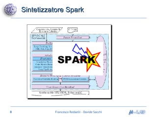
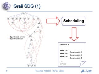
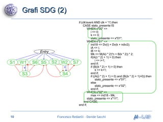
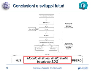

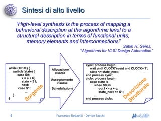
Il documento analizza metodologie di sintesi di alto livello per sviluppare un sintetizzatore automatico, confrontando metodi esistenti come ASM e Spark. Viene presentato un nuovo approccio basato su grafi SDG, evidenziando i risultati ottenuti attraverso vari algoritmi e simulazioni. Si concludono con proposte per futuri sviluppi nel campo della sintesi di alto livello.


