Downloaded 66 times


![42
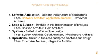
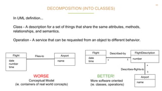
DECOMPOSITION (INTO CONCEPTUAL MODEL)
● The quintessential object-oriented step in analysis or investigation is the
decomposition of the problem into individual concepts -- the things we are
aware of.
● Conceptual Model - A representation of concepts in a problem domain.
● The focus of a conceptual model may show:
○ Concepts
○ Associations between concepts
○ Attributes of concepts
Flight
date
time
Real-world concept
not a software class
or artifact. A container.
FlightDatabase
date[ ]
time[ ]
Software artifact. NOT
a real-world concept
AVOID
YES!](https://image.slidesharecdn.com/thelanguageofarchitecture-mchenry-180718181511/85/The-Language-of-Application-Architecture-42-320.jpg)


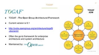


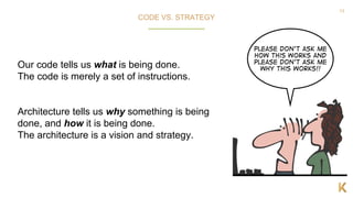
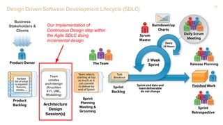
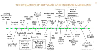
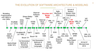
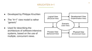
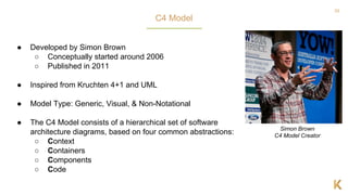
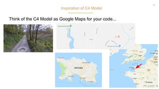
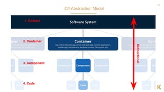
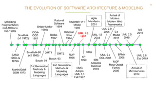
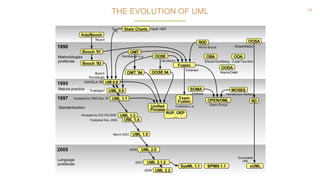
The document provides insights into the role and skills of software architects, emphasizing the importance of continuous design and application architecture principles. It discusses key architectural concepts, models, and frameworks, including the C4 model and UML, while highlighting the evolution of software architecture and design patterns. Additionally, it addresses challenges in the architecture field, such as the balance between agile development and design discipline.