2. 126b30ba-8149-4095-85e1-9b5e96be32ec-150616195816-lva1-app6892 6/16/2015 Page 1 o
Change History Page
09/23/14 Original document created.
10/03/14 Changes made to document to reflect Dr. DeLyser’s comments
10/06/14 Changes made to document prior to Requirements Review
11/10/14 Changes made to document prior to End of Quarter Design Review
02/04/15 Changes made to document prior to Proof of Concept Review
04/07/15 Second tier requirements and insulation requirements removed upon change in
Team member numbers to accommodate limited man power
4. 126b30ba-8149-4095-85e1-9b5e96be32ec-150616195816-lva1-app6892 6/16/2015 Page 3 o
1.0 INTRODUCTION
1.1 Project Description
Structures are necessary all over the world from suburban homes to office buildings to
makeshift huts in the desert. In many cases, expense and speed are two very important
qualities that must be taken into consideration for these structures. This brings a need for a
simple building that will maintain stability in various conditions and can be easily built.
Because this is such a widespread problem in the world, many organizations have
systems already in place. The UNHCR (United Nations High Commissioner for Refugees)
commonly uses canvas tents when aiding refugees and internally displaced people [1]. While
these tents are inexpensive with only one unit costing $500 [2], living in one provides very
little dignity to the user. Despite over millions of internally displaced people and refugees,
there are very few international standards when it comes to humanitarian aid, specifically
with the use of temporary structures. There are some standards on general fire safety,
structural strength of tent fabrics and specifications of structures; however, these do not
provide adequate guidance when it comes to environmental risks. Tents are also very
inefficient in terms of insulation. With just a thin layer of fabric between the interior and the
environment, the tents do not provide adequate shelter to the user. Heat is lost through
thermal conduction through the tent fabric, infiltration loss through leaks and holes, and heat
transfer to the ground. With such limited resources at their disposal, fuel is often an
extravagance that is neither affordable nor accessible. With fuel unavailable, alternatives
must be considered to keep the interior at a livable temperature. One such alternative that
should be considered is providing insulation within the structure [2].
Various patents have been granted describing a temporary structure that is more stable
than a tent. One such example was a structure that operates using tensioned cables as the
main framework with the cables tightened using a scissor frame design [3]. This design
however can be unstable and can be complicated to assemble. A building with a tensioned
cable frame that is simple to assemble is ideal. The design concept for this building which
utilizes turnbuckles to tension the frame system was created and patented by Diana
Etheridge [4].
The purpose of this document is to describe the requirements to be met by the Tensioned
Building being designed for Diana Etheridge by the Tensioned Building Construction design
team. This document is intended for Diana Etheridge. It is also intended for the members of
the Engineering Design Class, the instructor, and Dr. Gordon, the faculty consultant for the
project.
The motivation for this projects stems from Diana Etheridge’s patent for a building
construction with an integrated tensioned support system [4]. This system allows for the
rapid and inexpensive construction of conventionally appearing buildings in areas with
limited resources (both economically and physically), limited access, or both.
5. 126b30ba-8149-4095-85e1-9b5e96be32ec-150616195816-lva1-app6892 6/16/2015 Page 4 o
1.2 Scope
This document describes the requirements to be met by the Tensioned Building. It describes
the foundation, frame, tensioning, and enclosure of the structure. This document will
describe the conditions that are imposed on the system and provide a basis for the expected
conditions that this system will be able to support.
1.3 Definitions, Acronyms
PVC – polyvinyl chloride
2.0 APPLICABLE DOCUMENTS
2.1 Legal Documents
Building Construction for Tensioned Support System patent [4].
Wind or Fire Protection System for Structures patent application [5].
2.2 Project Documents
Tensioned Building Construction RFP [6].
Requirements document for Tensioned Building Construction design project [7].
3.0 ASSUMPTIONS and DEPENDENCIES
This design is operating under the assumption that the structure will not be operating within
an extreme environment (i.e. sand, swamp, snow)
The tensioned system will be operated using turn buckles [4].
The tensioned system will be attached to the foundation using hooks and rings [4].
6. 126b30ba-8149-4095-85e1-9b5e96be32ec-150616195816-lva1-app6892 6/16/2015 Page 5 o
4.0 Context Diagram
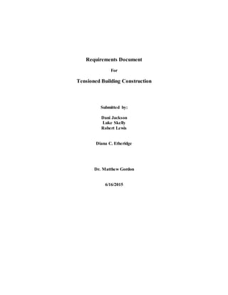
Figure 1 shows a top level context diagram describing the system development process. This
diagram is used to help define the requirements listed below. The inputs define the system needs
and intended use, while the controls and enablers show how the system interacts with external
factors. The relationship between the system inputs and these external factors yield the system
outputs: the implemented design and its accompanying design documentation. The full
description of this concept will be further detailed in the design document.
Controls
-Windows of Opportunity
Need for low cost, easy to
build structures across the
world
Inputs
-Customer Needs
Easily assembled/transported
Inexpensive to manufacture
Aesthetically
pleasing/functional
-Intended Use
Manufactured homes/offices
& temporary shelters
Military structures
-Business Needs
Simple, effective, and easy to
build structures for sheltering
displaced families
Accessible in remote
locations
System
Development
Process
Outputs
-Implemented Design
Tensioned Building
Construction
-Complete Design
Documentation
(includes requirements, test
reports, schematics, drawings,
process instructions, V&V
documentation)
Enablers
-Subject Matter Experts
Mrs. Etheridge (Flexystems)
John Buckley
(Manufacturing)
-University of Denver
Engineering Design Team
-Conceptual Prototypes
Figure 1: Top Level Context Diagram
7. 126b30ba-8149-4095-85e1-9b5e96be32ec-150616195816-lva1-app6892 6/16/2015 Page 6 o
5.0 Requirements
5.1.0 General System Requirements
5.1.1 The system shall function as a shelter, providing general protection from the
environment.
5.1.2 The budget for the design and construction of this system is $2000, which shall be
provided by Diana Etheridge.
5.1.3 Design must adhere to all restrictions set by U.S. Patent 5,930,971 [4].
5.1.4 To conform to standard pallet shipping practices, the unassembled materials will
not exceed an 8’x8’x10’ volume.
5.1.5 Assembly of the tension, structure, and enclosure subsystems shall not take longer
than 24 hours.
5.1.6 The area of the assembled structure shall be at least 11’x12’ in size and at least 9’
tall.
5.2.0 Foundation Requirements
5.2.1 Foundational blocks shall be located below ground.
5.2.2 Location of foundational blocks shall be clearly marked with indicators.
5.3.0 Tension Requirements
5.3.1 Cables shall be connected to the foundational blocks to secure structural supports
when tensioned.
5.3.2 Turnbuckles shall be accessible during assembly, use of the structure, and
disassembly.
5.4.0 Structure Requirements
5.4.1 The structure shall support the tensioned cables and enclosure material.
5.5.0 Enclosure Requirements
5.5.1 The entire structure shall be enclosed including roof, floor and walls.
5.5.2 The enclosure material shall be fastened to the structure.
5.5.3 The enclosure shall consist of at least one door and two windows.
8. 126b30ba-8149-4095-85e1-9b5e96be32ec-150616195816-lva1-app6892 6/16/2015 Page 7 o
6.0 TEST AND VERIFICATION (or QUALITY ASSURANCE PROVISIONS)
6.1 Calculations will be performed to determine the normal force that would be applied to the
structure due to high winds. These calculations will be used to simulate the applied force on
the structure (5.1.1).
6.2 The budget of each subsystem shall be tracked to determine the percentage that each
subsystem costs of the entire system (5.1.2).
6.3 A person or group of people without engineering expertise will be asked to assemble the
structure to verify that engineering expertise is not required for assembly of the structure
(5.1.4).
6.4 The structure shall be assembled and timed to verify that the structure can be assembled
within a certain time period (5.1.5).
6.5 The measurements of the structure will be noted to verify that the entire system maintains
size constraints (5.1.6).
6.6 After the foundational blocks have been placed underground the location of the blocks will
be determined by someone with no previous knowledge of their placement (5.2.1, 5.2.2).
6.7 The tension within the cable system will be measured to test stress applied to the structure
(5.3.1, 5.4.1).
6.8 During each phase of construction and after construction has been completed, access of
turnbuckles shall be tested (5.3.2).
6.9 The enclosure material will be tested by comparing the rate of heat loss with the enclosure
securely fastened and with the enclosure loosely fastened (5.5.1, 5.5.2).
9. 126b30ba-8149-4095-85e1-9b5e96be32ec-150616195816-lva1-app6892 6/16/2015 Page 8 o
7.0 Traceability Analysis Matrix
Table 1, below, shows a traceability analysis matrix which consolidates the above statements
comparing testing procedures to the requirements. The matrix makes it easier to see the
completeness of the testing procedures and verify that all of the requirements are in fact being
tested. Requirements 5.1.3 and 5.5.3 have been determined to be observable requirements. This
was chosen for requirement 5.1.3 because cross-referencing the patent document, which defines
the system, with the system itself will verify the requirement. Requirement 5.5.3 can be visually
verified once the system is built.
Test
Satisfied Requirements 4.x.x
1.1 1.2 1.3 1.4 1.5 1.6 2.1 2.2 3.1 3.2 4.1 5.1 5.2 5.3
6.1 X
6.2 X
6.3 X
6.4 X
6.5 X
6.6 X X
6.7 X X
6.8 X X
6.9 X
Table 1: Traceability analysis matrix; an X shows that the test in the marked row corresponds
with the requirement in the marked column. The grayed out requirement columns have been
determined to be observable requirement.
10. 126b30ba-8149-4095-85e1-9b5e96be32ec-150616195816-lva1-app6892 6/16/2015 Page 9 o
8.0 REFERENCES
[1] UNHCR – UN Refugee Agency “Shelter” from www.unhcr.org/pages/49c3646cf2.html
[2] Manfield, P and Ashmore, J and Corsellis, T. 2004. “Design of humanitarian tents for use
in cold climate” Building and Research Information, 32(5) pp. 368-378
[3] Ziegler, Theodore R. Mechanically deployable expandable and collapsible structure and
method for deploying structure. World Shelters, Inc., assignee. Patent 7533498. 19 May
2009. Print.
[4] Etheridge, Diana C. Building Construction with Tensioned Support System. Diana C.
Etheridge, assignee. Patent 5,930,971. 3 August 1999. Print.
[5] Etheridge, Diana C. Wind or Fire Protection System for Structures. Diana C. Etheridge,
assignee. Patent Application 14/311,634. 23 June 2014. Print.
[6] Etheridge, Diana C. (2014) Request for Proposal. University of Denver’s School of
Engineering and Computer Science.