Download to read offline
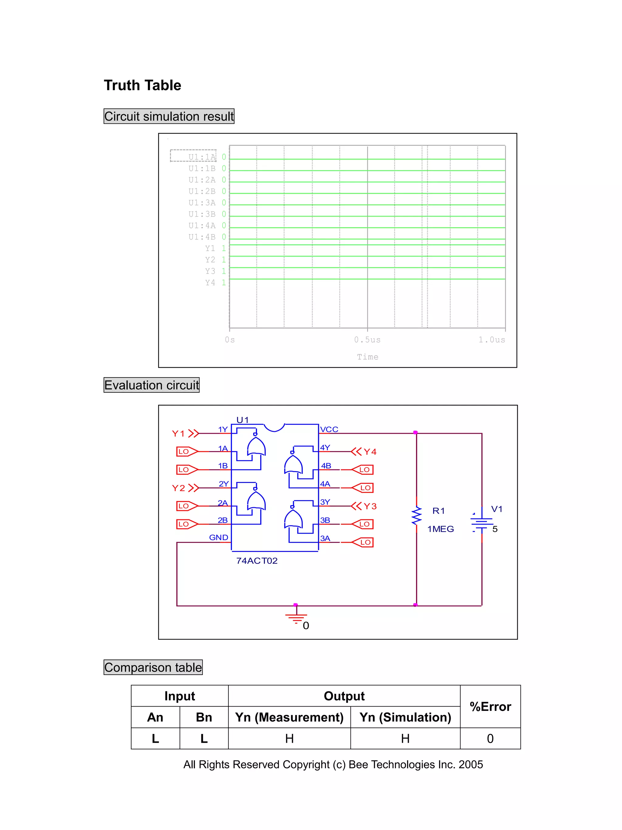


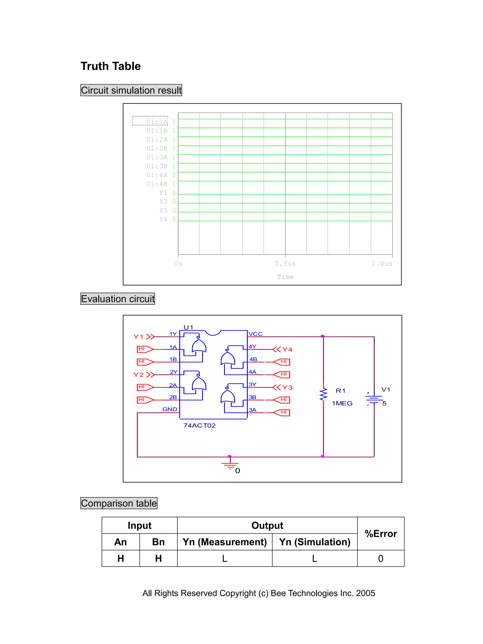
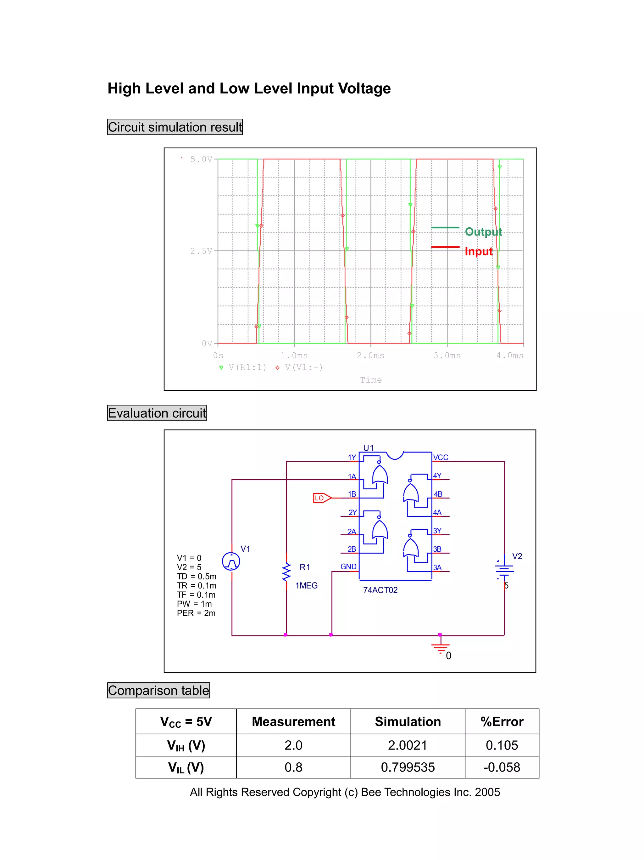
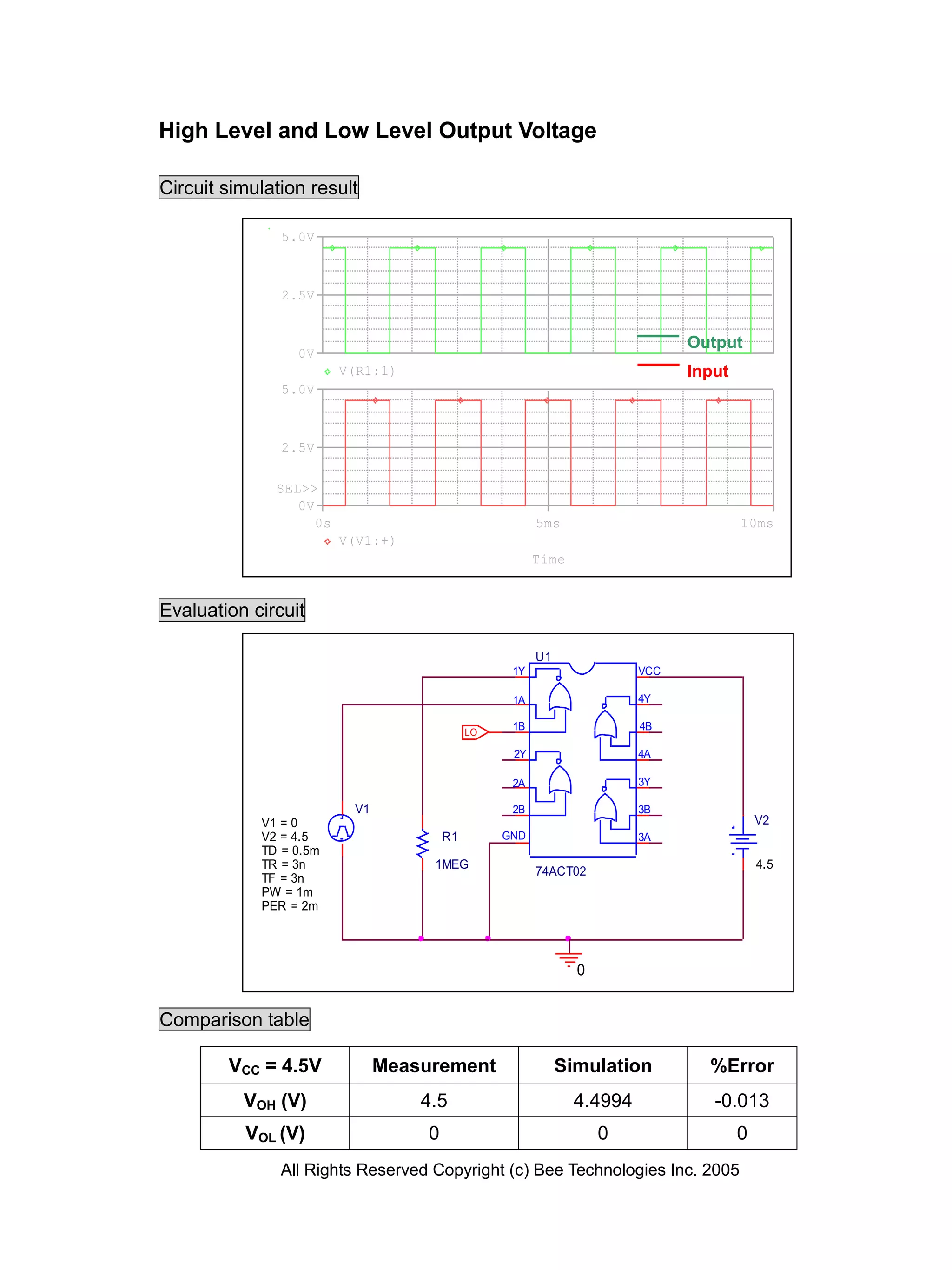
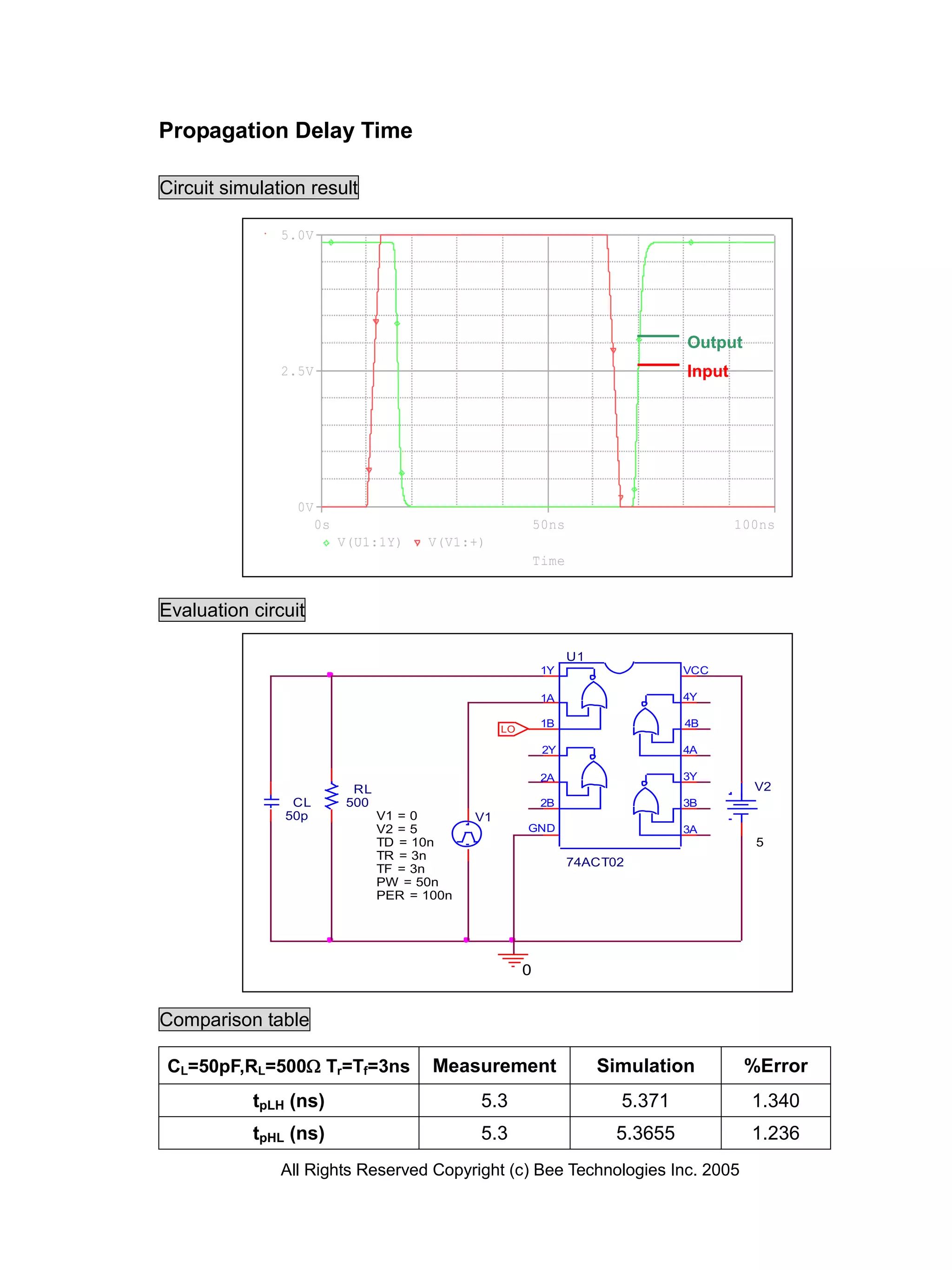

The document is a device modeling report for the TC74ACT02F CMOS digital integrated circuit by Toshiba Bee Technologies, detailing circuit simulation results, truth tables, and comparison tables for input-output performance with specified error margins. It includes various simulation tests for high and low voltage levels, propagation delays, and input/output measurements, all under specific conditions. The report contains detailed technical findings from the circuit simulations emphasizing the accuracy and reliability of the device's performance.


