Systems Analysis And Design Uml Version 20 An Objectoriented Approach Alan Dennis
Systems Analysis And Design Uml Version 20 An Objectoriented Approach Alan Dennis
Systems Analysis And Design Uml Version 20 An Objectoriented Approach Alan Dennis
Systems Analysis And Design Uml Version 20 An Objectoriented Approach Alan Dennis
Systems Analysis And Design Uml Version 20 An Objectoriented Approach Alan Dennis
1.
Systems Analysis AndDesign Uml Version 20 An
Objectoriented Approach Alan Dennis download
https://ebookbell.com/product/systems-analysis-and-design-uml-
version-20-an-objectoriented-approach-alan-dennis-43714672
Explore and download more ebooks at ebookbell.com
2.
Here are somerecommended products that we believe you will be
interested in. You can click the link to download.
Systems Analysis And Design An Objectoriented Approach With Uml 6th
Dennis
https://ebookbell.com/product/systems-analysis-and-design-an-
objectoriented-approach-with-uml-6th-dennis-56242270
Systems Analysis And Design An Objectoriented Approach With Uml 5th
Edition Alan Dennis
https://ebookbell.com/product/systems-analysis-and-design-an-
objectoriented-approach-with-uml-5th-edition-alan-dennis-5523792
Systems Analysis And Design With Uml 3rd Edition Alan Dennis
https://ebookbell.com/product/systems-analysis-and-design-with-
uml-3rd-edition-alan-dennis-2618042
Systems Analysis And Design With Uml International Edition 2nd Edition
Wiley International Edition Alan Dennis
https://ebookbell.com/product/systems-analysis-and-design-with-uml-
international-edition-2nd-edition-wiley-international-edition-alan-
dennis-55582212
3.
Objectoriented Systems AnalysisAnd Design Using Uml 4th Edition Simon
Bennett
https://ebookbell.com/product/objectoriented-systems-analysis-and-
design-using-uml-4th-edition-simon-bennett-23610970
Uml A Simple Guide For Beginners A Basic Guide To Systems Analysis And
Design Martins Consiglio Regis
https://ebookbell.com/product/uml-a-simple-guide-for-beginners-a-
basic-guide-to-systems-analysis-and-design-martins-consiglio-
regis-58430342
Objectoriented Analysis And Design For Information Systems Modeling
With Uml Ocl And Ifml Raul Sidnei Wazlawick Auth
https://ebookbell.com/product/objectoriented-analysis-and-design-for-
information-systems-modeling-with-uml-ocl-and-ifml-raul-sidnei-
wazlawick-auth-4634242
Objectoriented Analysis And Design Understanding System Development
With Uml 20 First Mike Odocherty
https://ebookbell.com/product/objectoriented-analysis-and-design-
understanding-system-development-with-uml-20-first-mike-
odocherty-927962
Systems Analysis And Design 5th Alan Dennis Barbara Haley Wixom
https://ebookbell.com/product/systems-analysis-and-design-5th-alan-
dennis-barbara-haley-wixom-45446706
6.
S
System Analysis D
Design
UMLVersion 2
2.0
AN OBJECT-ORIENTED APPROACH
Fourth Edition
Alan D
Dennis
Indiana University
Barbara H
Haley Wixom
University of Virginia
David Tegarden
Virginia Tech
John Wiley &
& S
Sons, I
Inc.
i
iii
C O N
NT
T E
E N
N T
T S
S
Preface IX
Chapter 1
1
Introduction t
to S
Systems
Analysis a
and D
Design
n 1
INTRODUCTION 2
THE SYSTEMS DEVELOPMENT LIFE CYCLE 3
Planning 4
Analysis 4
Design 5
Implementation 6
SYSTEMS DEVELOPMENT
METHODOLOGIES 6
Structured Design 8
Rapid Application Development
(RAD) 10
Agile Development 14
Selecting the Appropriate Development
Methodology 18
TYPICAL SYSTEMS ANALYST ROLES
AND SKILLS 20
Business Analyst 21
Systems Analyst 21
Infrastructure Analyst 22
Change Management Analyst 22
Project Manager 22
BASIC CHARACTERISTICS OF OBJECT-
ORIENTED SYSTEMS 23
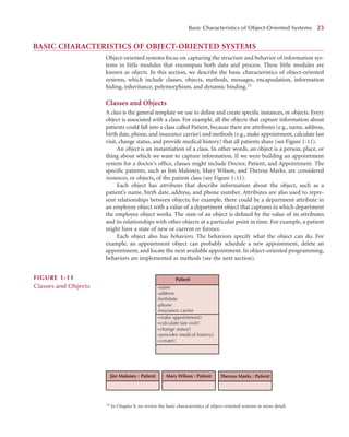
Classes and Objects 23
Methods and Messages 24
Encapsulation and Information
Hiding 24
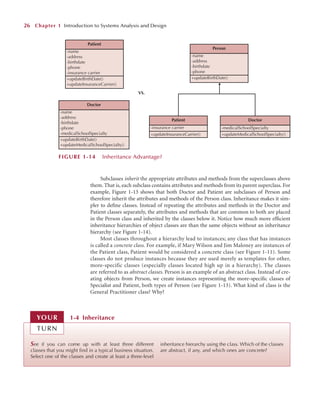
Inheritance 25
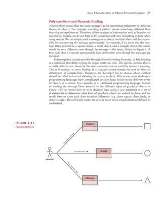
Polymorphism and Dynamic Binding 27
OBJECT-ORIENTED SYSTEMS ANALYSIS
AND DESIGN (OOSAD) 28
Use-Case Driven 28
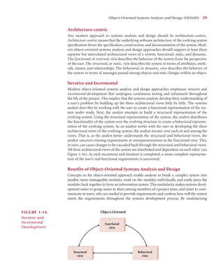
Architecture-centric 29
Iterative and Incremental 29
Benefits of Object-Oriented Systems Analysis
and Design 29
THE UNIFIED PROCESS 30
Phases 30
Workflows 32
Extensions to the Unified Process 35
THE UNIFIED MODELING LANGUAGE 39
APPLYING THE CONCEPTS AT CD
SELECTIONS 41
Summary 41
■ Chapter 2
2
Project Management
t 48
INTRODUCTION 49
PROJECT IDENTIFICATION 51
System Request 52
FEASIBILITY ANALYSIS 54
Technical Feasibility 55
Economic Feasibility 56
Organizational Feasibility 64
PROJECT SELECTION 66
TRADITIONAL PROJECT MANAGEMENT TOOLS 69
Work Breakdown Structures 70
Gantt Chart 71
Network Diagram 71
PROJECT EFFORT ESTIMATION 73
CREATING AND MANAGING
THE WORKPLAN 79
Evolutionary Work Breakdown Structures and
Iterative Workplans 79
Managing Scope 84
Timeboxing 84
Refining Estimates 86
Managing Risk 87
STAFFING THE PROJECT 88
Characteristics of a Jelled Team 88
Staffing Plan 90
Motivation 93
Handling Conflict 94
9.
ENVIRONMENT AND INFRASTRUCTURE
MANAGEMENT96
CASE Tools 96
Standards 97
Documentation 98
APPLYING THE CONCEPTS AT CD
SELECTIONS 100
Summary 100
■ PART ONE
ANALYSIS MODELING 107
C
Chapter 3
3
Requirements
Determination
n 109
INTRODUCTION 110
REQUIREMENTS DETERMINATION 110
Defining a Requirement 112
Requirements Definition 115
Determining Requirements 116
Creating a Requirements Definition 117
Real-World Problems with Requirements
Determination 117
REQUIREMENTS ANALYSIS STRATEGIES 118
Business Process Automation (BPA) 118
Business Process Improvement
(BPI) 121
Business Process Reengineering 122
Selecting Appropriate Strategies 123
REQUIREMENTS-GATHERING
TECHNIQUES 125
Interviews 126
Joint Application Development
(JAD) 132
Questionnaires 136
Document Analysis 138
Observation 139
Selecting the Appropriate
Techniques 141
ALTERNATIVE REQUIREMENTS
DOCUMENTATION TECHNIQUES 143
Concept Maps 144
Story Cards and Task Lists 144
THE SYSTEM PROPOSAL 146
APPLYING THE CONCEPTS AT CD
SELECTIONS 147
Summary 148
Chapter 4
4
Business P
Process and
Functional M
Modeling
g 153
INTRODUCTION 154
BUSINESS PROCESS IDENTIFICATION
WITH USE CASES AND USE-CASE
DIAGRAMS 155
Elements of Use Case Diagrams 155
Identifying the Major Use Cases 160
Creating a Use-Case Diagram 161
BUSINESS PROCESS MODELING WITH
ACTIVITY DIAGRAMS 163
Elements of an Activity Diagram 165
Guidelines for Creating Activity
Diagrams 170
Creating Activity Diagrams 171
BUSINESS PROCESS DOCUMENTATION
WITH USE CASES AND USE-CASE
DESCRIPTIONS 173
Types of Use Cases 175
Elements of a Use-Case Description 175
Guidelines for Creating Use-Case
Descriptions 179
Creating Use Case Descriptions 180
VERIFYING AND VALIDATING THE BUSINESS PROCESSES
AND FUNCTIONAL
MODELS 184
Verification and Validation through
Walkthroughs 184
Functional Model Verification and
Validation 185
APPLYING THE CONCEPTS AT
CD SELECTIONS 188
Summary 188
■ Chapter 5
5
Structural M
Modeling
g 195
INTRODUCTION 195
STRUCTURAL MODELS 196
Classes, Attributes, and Operations 197
Relationships 197
OBJECT IDENTIFICATION 199
Textual Analysis 199
Brainstorming 201
Common Object Lists 201
Patterns 202
iv Contents
10.
CRC CARDS 205
Responsibilitiesand Collaborations 205
Elements of a CRC Card 206
Role-Playing CRC Cards with Use Cases 207
CLASS DIAGRAMS 208
Elements of a Class Diagram 208
Simplifying Class Diagrams 217
Object Diagrams 217
CREATING STRUCTURAL MODELS USING
CRC CARDS AND CLASS DIAGRAMS 218
Example 220
VERIFYING AND VALIDATING THE
STRUCTURAL MODEL 227
APPLYING THE CONCEPTS AT CD SELECTIONS 230
Summary 231
C
Chapter 6
6
Behavioral M
Modeling
g 236
INTRODUCTION 236
BEHAVIORAL MODELS 237
INTERACTION DIAGRAMS 238
Objects, Operations, and Messages 238
Sequence Diagrams 238
Communication Diagrams 246
BEHAVIORAL STATE MACHINES 253
States, Events, Transitions, Actions,
and Activities 253
Elements of a Behavioral State Machine 255
Creating a Behavioral State Machine 258
CRUDE ANALYSIS 260
VERIFYING AND VALIDATING THE
BEHAVIORAL MODEL 264
APPLYING THE CONCEPTS AT CD SELECTIONS 266
Summary 266
■ PART TWO
DESIGN MODELING 271
Chapter 7
7
Moving o
on t
to D
Design
n 273
INTRODUCTION 274
VERIFYING AND VALIDATING THE ANALYSIS
MODELS 275
Balancing Functional and
Structural Models 276
Balancing Functional and
Behavioral Models 278
Balancing Structural and Behavioral
Models 287
Summary 289
EVOLVING THE ANALYSIS MODELS INTO DESIGN
MODELS 289
Factoring 291
Partitions and Collaborations 292
Layers 293
PACKAGES AND PACKAGE DIAGRAMS 296
Guidelines for Creating Package
Diagrams 298
Creating Package Diagrams 300
Verifying and Validating Package
Diagrams 302
DESIGN STRATEGIES 302
Custom Development 303
Packaged Software 304
Outsourcing 305
Selecting a Design Strategy 307
DEVELOPING THE ACTUAL DESIGN 309
Alternative Matrix 310
APPLYING THE CONCEPTS AT CD
SELECTIONS 311
Summary 311
Chapter 8
8
Class a
and M
Method
Design
n 317
7
INTRODUCTION 317
REVIEW OF THE BASIC CHARACTERISTICS
OF OBJECT ORIENTATION 319
Classes, Objects, Methods, and Messages 320
Encapsulation and Information Hiding 320
Polymorphism and Dynamic Binding 320
Inheritance 321
DESIGN CRITERIA 325
Coupling 325
Cohesion 328
Connascence 330
OBJECT DESIGN ACTIVITIES 331
Adding Specifications 332
Identifying Opportunities for Reuse 333
Contents v
11.
Restructuring the Design336
Optimizing the Design 337
Mapping Problem-Domain Classes to
Implementation Languages 340
CONSTRAINTS AND CONTRACTS 343
Types of Constraints 345
Elements of a Contract 348
METHOD SPECIFICATION 354
General Information 354
Events 354
Message Passing 356
Algorithm Specifications 356
Example 357
APPLYING THE CONCEPTS AT CD SELECTIONS 361
Summary 362
C
Chapter 9
9
Data M
Management L
Layer
Design
n 367
INTRODUCTION 368
OBJECT PERSISTENCE FORMATS 368
Sequential and Random Access Files 369
Relational Databases 372
Object-Relational Databases 374
Object-Oriented Databases 374
NoSQL Data Stores 375
Selecting an Object persistence
Format 377
MAPPING PROBLEM DOMAIN OBJECTS TO OBJECT
PERSISTENCE FORMATS 380
Mapping Problem Domain Objects to an
OODBMS Format 380
Mapping Problem Domain Objects to an
ORDBMS Format 384
Mapping Problem Domain Objects to a
RDBMS Format 387
OPTIMIZING RDBMS-BASED OBJECT
STORAGE 390
Optimizing Storage Efficiency 390
Optimizing Data Access Speed 396
Estimating Data Storage Size 400
DESIGNING DATA ACCESS AND
MANIPULATION CLASSES 401
NONFUNCTIONAL REQUIREMENTS AND DATA
MANAGEMENT LAYER DESIGN 405
APPLYING THE CONCEPTS AT CD SELECTIONS 406
Summary 406
Chapter 1
10
Human–Computer I
Interaction
Layer D
Design
n 412
INTRODUCTION 413
PRINCIPLES FOR USER INTERFACE
DESIGN 414
Layout 414
Content Awareness 416
Aesthetics 418
User Experience 420
Consistency 420
Minimizing User Effort 421
USER INTERFACE DESIGN PROCESS 421
Use Scenario Development 422
Interface Structure Design 425
Interface Standards Design 426
Interface Design Prototyping 427
Interface Evaluation 432
Common Sense Approach to User
Interface Design 434
NAVIGATION DESIGN 435
Basic Principles 436
Types of Navigation Controls 437
Messages 440
Navigation Design Documentation 441
INPUT DESING 443
Basic Principles 443
Types of Inputs 445
Input Validation 448
OUTPUT DESING 448
Basic Principles 448
Types of Outputs 451
Media 451
MOBILE COMPUTING AND USER INTERFACE
DESIGN 453
SOCIAL MEDIA AND USER INTERFACE
DESIGN 456
INTERNATIONAL AND CULTURAL ISSUES AND USER
INTERFACE DESIGN 459
Multilingual Requirements 459
Color 460
Cultural Differences 461
NONFUNCTIONAL REQUIREMENTS AND
HUMAN–COMPUTER INTERACTION
LAYER DESIGN 463
APPLYING THE CONCEPTS AT CD
SELECTIONS 464
Summary 464
vi Contents
12.
C
Chapter 1
11
Physical ArchitectureL
Layer
Design
n 473
3
INTRODUCTION 473
ELEMENTS OF THE PHYSICAL ARCHITECTURE
LAYER 474
Architectural Components 474
Server-Based Architectures 475
Client-Based Architectures 476
Client–Server Architectures 476
Client–Server Tiers 478
Selecting a Physical Architecture 479
CLOUD COMPUTING 482
GREEN IT 485
INFRASTRUCTURE DESING 486
Deployment Diagram 486
Network Model 489
HARDWARE AND SYSTEM SOFTWARE
SPECIFICATIONS 492
NONFUNCTIONAL REQUIREMENTS AND
PHYSICAL ARCHITECTURE LAYER DESIGN 495
Operational Requirements 495
Performance Requirements 498
Security Requirements 500
Cultural and Political Requirements 503
Synopsis 504
APPLYING THE CONCEPTS AT CD SELECTIONS 507
Summary 507
■ PART THREE
CONSTRUCTION, INSTALLATION,
AND OPERATIONS 513
Chapter 1
12
Construction
n 515
INTRODUCTION 515
MANAGING PROGRAMMING 517
Assigning Programmers 517
Coordinating Activities 518
Managing the Schedule 519
Cultural Issues 520
DESIGNING TESTS 525
Testing and Object Orientation 526
Test Planning 528
Unit Tests 530
Integration Tests 534
System Tests 534
Acceptance Tests 535
DEVELOPING DOCUMENTATION 535
Types of Documentation 536
Designing Documentation Structure 537
Writing Documentation Topics 538
Identifying Navigation Terms 539
APPLYING THE CONCEPTS AT CD
SELECTIONS 541
Summary 541
Chapter 1
13
Installation a
and
Operations
s 5
545
INTRODUCTION 545
CULTURAL ISSUES AND INFORMATION
TECHNOLOGY ADOPTION 547
CONVERSION 549
Conversion Style 550
Conversion Location 551
Conversion Modules 552
Selecting the Appropriate Conversion
Strategy 553
CHANGE MANAGEMENT 555
Understanding Resistance to Change 556
Revising Management Policies 558
Assessing Costs and Benefits 559
Motivating Adoption 561
Enabling Adoption: Training 562
POST-IMPLEMENTATION ACTIVITIES 564
System Support 564
System Maintenance 566
Project Assessment 567
APPLYING THE CONCEPTS AT CD
SELECTIONS 569
Summary 569
INDEX 574
Available on line at
www.wiley.com/college/dennis
APPENDIX 1
APPENDIX 2
APPENDIX 3
Contents vii
13.
PURPOSE OF THISBOOK
Systems Analysis and Design (SAD) is an exciting, active field in which analysts continually
learn new techniques and approaches to develop systems more effectively and efficiently.
However there is a core set of skills that all analysts need to know—no matter what
approach or methodology is used. All information systems projects move through the four
phases of planning, analysis, design, and implementation; all projects require analysts to
gather requirements, model the business needs, and create blueprints for how the system
should be built; and all projects require an understanding of organizational behavior con-
cepts like change management and team building. Today, the cost of developing modern
software is composed primarily of the cost associated with the developers themselves and
not the computers. As such, object-oriented approaches to developing information systems
hold much promise in controlling these costs.
Today, the most exciting change to systems analysis and design is the move to object-
oriented techniques, which view a system as a collection of self-contained objects that have
both data and processes. This change has been accelerated through the creation of the Uni-
fied Modeling Language (UML). UML provides a common vocabulary of object-oriented
terms and diagramming techniques that is rich enough to model any systems development
project from analysis through implementation.
This book captures the dynamic aspects of the field by keeping students focused on
doing SAD while presenting the core set of skills that we feel every systems analyst needs to
know today and in the future. This book builds on our professional experience as systems
analysts and on our experience in teaching SAD in the classroom.
This book will be of particular interest to instructors who have students do a major
project as part of their course. Each chapter describes one part of the process, provides clear
explanations on how to do it, gives a detailed example, and then has exercises for the
students to practice. In this way, students can leave the course with experience that will
form a rich foundation for further work as a systems analyst.
OUTSTANDING FEATURES
A Focus on Doing SAD
The goal of this book is to enable students to do SAD—not just read about it, but under-
stand the issues so they can actually analyze and design systems. The book introduces
each major technique, explains what it is, explains how to do it, presents an example,
and provides opportunities for students to practice before they do it for real in a project.
After reading each chapter, the student will be able to perform that step in the system
development process.
P R
R E
E F
F A C
C E
ix
14.
x
x Preface
Rich Examplesof Success and Failure
The book includes a running case about a fictitious company called CD Selections. Each
chapter shows how the concepts are applied in situations at CD Selections. Unlike running
cases in other books, we have tried to focus these examples on planning, managing, and
executing the activities described in the chapter, rather than on detailed dialogue between
fictitious actors. In this way, the running case serves as a template that students can apply
to their own work. Each chapter also includes numerous Concepts in Action boxes, many
of which were written by Dr. Bruce White from Quinnipiac University, that describe how
real companies succeeded—and failed—in performing the activities in the chapter.
Real World Focus
The skills that students learn in a systems analysis and design course should mirror the
work that they ultimately will do in real organizations. We have tried to make this book as
“real” as possible by building extensively on our experience as professional systems analysts
for organizations such as Arthur Andersen, IBM, the U.S. Department of Defense, and the
Australian Army. We have also worked with a diverse industry advisory board of IS profes-
sionals and consultants in developing the book and have incorporated their stories, feed-
back, and advice throughout. Many students who use this book will eventually use the skills
on the job in a business environment, and we believe they will have a competitive edge in
understanding what successful practitioners feel is relevant in the real world.
Project Approach
We have presented the topics in this book in the order in which an analyst encounters them
in a typical project. Although the presentation is necessarily linear (because students have
to learn concepts in the way in which they build on each other), we emphasize the iterative,
complex nature of SAD as the book unfolds. The presentation of the material should align
well with courses that encourage students to work on projects because it presents topics as
students need to apply them.
WHAT’S NEW IN THIS EDITION
In this edition, we have increased the coverage of and better organized the text around the
enhanced Unified Process; provided a greater focus on nonfunctional requirements; pro-
vided a greater emphasis on the iterative and incremental development associated with
object-oriented analysis and design; added figures and examples, along with additional
explanatory text that addresses some of the more difficult concepts to learn; better aligned
the CD selections case material; and did some major reorganization. Details of the major
changes are as follows:
1. Given the lack of object-oriented programming experience of the typical student
and the importance of understanding basic object-oriented concepts to perform
object-oriented systems analysis and design, the appendix entitled “Basic Charac-
teristics of Object-Oriented Systems” has been incorporated in Chapter 1.
2. Due to the popularity of the so-called agile approaches to systems development,
we have greatly increased their coverage throughout the text. In Chapter 1, we
have expanded the coverage of both XP and SCRUM. In Chapter 2, we have
added a section regarding “Jelled” teams and their importance when considering
staffing requirements of projects. In Chapter 3, we have added story cards and
15.
Preface x
xi
task listsas additional approaches for gathering and documenting requirements.
We have also greatly increased the focus on testing throughout the text. For
example, the verification and validation material in the Moving On to Design
chapter has been distributed over the analysis modeling chapters and the Moving
On to Design chapter.
3. Given the differences between traditional project management and object-
oriented project management, the project management material has been
rewritten to reflect more of an object-oriented flavor. However, since much of
the traditional project management material is still useful within an object-
oriented context, we still cover it, e.g., net present value and return on invest-
ment, break-even point, work breakdown structures, Gantt charts, network
diagrams and PERT analysis. The reorganization and rewriting of project
management material allowed us to apply better the iterative and incremental
development characteristics of object-oriented systems development to project
management. Finally, we replaced the project size estimation section with an
expansion of the use case points material that was in the functional modeling
chapter in the previous edition.
4. To increase the focus on business processes, we have reorganized and expanded
the functional modeling material. In this edition, minimize the potential over-
load of different notations used for business process modeling, e.g., the business
process modeling notation or data flow diagrams, we have aligned the use case
construct with the idea of a business process. Consequently, a use case diagram
can be used to provide an overview of the different business processes and how
they interrelate. Each use case can then be decomposed by creating an activity
diagram to represent the details of each use case. Furthermore, each use case can
be described with a use case description.
5. As in the third edition, the material included within the analysis modeling
chapters has been more tightly coupled. This is especially true with regard to
the idea of iterative and incremental development. The text now emphasizes that
systems must be incrementally built by iterating over each of the models and
over the intersection of the models. For example, the normal flow of events
contained within a use-case description is associated with the activities on an
activity diagram, the operations on a class diagram, the behaviors on the CRC
cards, the messages on sequence and communication diagrams, and transitions
on behavioral state machines. As such, any change to any one of these most likely
will force changes in the others. Furthermore, we have extended CRUD analysis
to CRUDE analysis that includes the idea of simply executing a method associated
with another object.
6. With regards to the requirements determination, we have expanded the coverage
of non-functional requirements throughout the design modeling chapters.
7. We have expanded the material that addresses global concerns. For example,
we have created a new section that addresses international and cultural issues
with regard to user interface design and we have expanded the coverage of
cultural issues with regards to construction and the installation and operations
of information systems.
8. Given all of the technological changes that have taken place since the third
edition, we have also included material that addresses NoSQL data stores, mobile
computing, social media, cloud computing, and green IT in the design modeling
chapters.
16.
x
xii Preface
9. Todecrease the cognitive load required for much of the material in the text,
additional figures and explanatory material have been added.
Finally, to provide a more complete version of the CD Selection case, we have moved the
case to an online format. However, at the end of each chapter in the text, a very short
synopsis of the case is provided.
ORGANIZATION OF THIS BOOK
This edition of the book is loosely organized around the phases and workflows of the
enhanced Unified Process. Each chapter has been written to teach students specific tasks
that analysts need to accomplish over the course of a project, and the deliverables that will
be produced from the tasks. As students complete the chapters, they will realize the itera-
tive and incremental nature of the tasks in object-oriented systems development.
Chapter 1 introduces the SDLC, systems development methodologies, roles and skills
needed for a systems analyst, the basic characteristics of object-oriented systems, object-
oriented systems analysis, the Unified Process, and the UML. Chapter 2 presents topics
related to the project management workflow of the Unified Process, including project iden-
tification, system request, feasibility analysis, project selection, traditional project manage-
ment tools (including work breakdown structures, network diagrams, and PERT analysis),
project effort estimation using use case points, evolutionary work breakdown structures,
iterative workplans, scope management, timeboxing, risk management, and staffing the
project. Chapter 2 also addresses issues related to the Environment and Infrastructure
management workflows of the Unified Process.
Part One focuses on creating analysis models. Chapter 3 introduces students to an
assortment of analysis techniques to help with business automation, business improvement,
and business process reengineering, a variety of requirements-gathering techniques that are
used to determine the functional and nonfunctional requirements of the system, and to a
system proposal. Chapter 4 focuses on constructing business process and functional models
using use case diagrams, activity diagrams, and use case descriptions. Chapter 5 addresses
producing structural models using CRC cards, class diagrams, and object diagrams. Chap-
ter 6 tackles creating behavioral models using sequence diagrams, communication dia-
grams, behavioral state machines, and CRUDE analysis and matrices. Chapters 4 through 6
also cover the verification and validation of the models described in each chapter.
Part Two addresses design modeling. In Chapter 7, students learn how to verify and vali-
date the analysis models created during analysis modeling and to evolve the analysis models
into design models via the use of factoring, partitions, and layers. The students also learn to
create an alternative matrix that can be used to compare custom, packaged, and outsourcing
alternatives. Chapter 8 concentrates on designing the individual classes and their respective
methods through the use of contracts and method specifications. Chapter 9 presents the issues
involved in designing persistence for objects. These issues include the different storage formats
that can be used for object persistence, how to map an object-oriented design into the chosen
storage format, and how to design a set of data access and manipulation classes that act as a
translator between the classes in the application and the object persistence. This chapter also
focuses on the nonfunctional requirements that impact the data management layer. Chapter
10 presents the design of the human–computer interaction layer, where students learn how to
design user interfaces using use scenarios, windows navigation diagrams, storyboards, win-
dows layout diagrams, HTML prototypes, language prototypes, real use cases, interface stan-
dards, and user interface templates, to perform user interface evaluations using heuristic
evaluation, walkthrough evaluation, interactive evaluation, and formal usability testing, and to
17.
Preface x
xiii
address nonfunctionalrequirements such as user interface layout, content awareness, aesthet-
ics, user experience, and consistency. This chapter also addresses issues related to mobile com-
puting, social media, and international and cultural issues with regards to user interface
design. Chapter 11 focuses on the physical architecture and infrastructure design, which
includes deployment diagrams and hardware/software specification. In today’s world, this also
includes issues related to cloud computing and green IT. This chapter, like the previous design
chapters, covers the impact that nonfunctional requirements can have on the physical archi-
tecture layer.
Part Three provides material that is related to the construction, installation, and oper-
ations of the system. Chapter 12 focuses on system construction, where students learn how
to build, test, and document the system. Installation and operations are covered in Chap-
ter 13, where students learn about the conversion plan, change management plan, support
plan, and project assessment. Additionally, these chapters address the issues related to
developing systems in a flat world, where developers and users are distributed throughout
the world.
ACKNOWLEDGMENTS
For the fourth edition, we would like to thank the students of the ACIS 3515: Information
Systems Development I and ACIS 3516: Information Systems Development II classes at
Virginia Tech for giving many suggestions that drove most of the changes from the third
edition to the fourth edition. We would like to especially thank Ashley, Ben, Daniel, Jason,
Jason, Jason (yes, there were three of them), Kyle, Lucy, and Omar. Their suggestions were
invaluable in improving the text and examples.
We would like to thank the following reviewers for their helpful and insightful com-
ments on the fourth edition: David Champion, DeVry University, Columbus, OH campus;
Jeff Cummings, Indiana University; Junhua Ding, East Carolina University; Robert
Dollinger, University of Wisconsin-Stevens Point; Abhijit Dutt, Carnegie Mellon Univer-
sity; Yujong Hwang, DePaul University; Zongliang Jiang, North Carolina A&T State
University; Raymond Kirsch, La Salle University; Gilliean Lee, Lander University; Steve
Machon, DeVry University; Makoto Nakayama, College of CDM, DePaul University; Para-
suraman Nurani, Devry University; Selwyn Piramuthu, University of Florida; Iftikhar
Sikder, Cleveland State University; Fan Zhao, Florida Gulf Coast University; and Dan Zhu,
Iowa State University.
For the third edition, we would like to thank the students of the ACIS 3515: Informa-
tion Systems Development I and ACIS 3516: Information Systems Development II classes
at Virginia Tech for giving many suggestions that drove most of the changes from the
second edition to the third edition. Their feedback was invaluable in improving the text
and examples.
We would also like to thank the following reviewers for their helpful and insightful
comments on the first, second, and third editions: Evans Adams, Fort Lewis College;
Murugan Anandarajon, Drexel University; Ron Anson, Boise State University; Noushin
Ashrafi, University of Massachusetts, Boston; Dirk Baldwin, University of Wisconsin-
Parkside; Robert Barker, University of Louisville; Qing Cao, University of Missouri–Kansas
City; Terry Fox, Baylor University; Ahmad Ghafarian, North Georgia College & State
University; Donald Golden, Cleve-land State University; Cleotilde Gonzalez, Carnegie
Melon University; Daniel V. Goulet, University of Wisconsin–Stevens Point; Harvey
Hayashi, Loyalist College of Applied Arts and Technology; Scott James, Saginaw Valley
State University; Rajiv Kishore, State University of New York–Buffalo; Ravindra Krovi,
University of Akron; Jean-Piere Kuilboer, University of Massachusetts, Boston; Leo
18.
x
xiv Preface
Legorreta, CaliforniaState University Sacramento; Diane Lending, James Madison
University; Major Fernando Maymi, West Point University; Daniel Mittleman, DePaul
University; Fred Niederman, Saint Louis University; H. Robert Pajkowski, DeVry Insti-
tute of Technology, Scarborough, Ontario; June S. Park, University of Iowa; Graham
Peace, West Virginia University; Tom Pettay, DeVry Institute of Technology, Columbus,
Ohio; J. Drew Procaccino, Rider University; Neil Ramiller, Portland State University;
Eliot Rich, University at Albany, State University of New York; Marcus Rothenberger,
University of Wisconsin–Milwaukee; Carl Scott, University of Houston; Keng Siau,
University of Nebraska–Lincoln; Jonathan Trower, Baylor University; June Verner, Drexel
University; Anna Wachholz, Sheridan College; Bill Watson, Indiana University–Purdue
University Indianapolis; Randy S.Weinberg, Carnegie Mellon University; Eli J.Weissman,
DeVry Institute of Technology, Long Island City, NY; Heinz Roland Weistroffer, Virginia
Commonwealth University; Amy Wilson, DeVry Institute of Technology, Decatur, GA;
Amy Woszczynski, Kennesaw State University; and Vincent C.Yen, Wright State University.
SUPPLEMENTS http://www.wiley.com/college/dennis
Instructor’s Resources Web Site
■ PowerPoint slides, which instructors can tailor to their classroom needs and that
students can use to guide their reading and studying activities
■ Test Bank, that includes a variety of questions ranging from multiple choice to
essay style questions. A computerized version of the Test Bank will also be available.
Online Instructor’s Manual
The Instructor’s Manual provides resources to support the instructor both inside and out
of the classroom:
■ Short experiential exercises that instructors can use to help students experience
and understand key topics in each chapter.
■ Short stories have been provided by people working in both corporate and con-
sulting environments for instructors to insert into lectures to make concepts
more colorful and real
■ Additional minicases for every chapter allow students to perform some of the key
concepts that were learned in the chapter.
■ Solutions to end of chapter questions and exercises are provided.
Student Website
■ Relevant Web links, including career resources Web site.
■ Web quizzes help students prepare for class tests.
Cases in Systems Analysis and Design
A separate Case Book on CD-ROM provides a set of more than a dozen cases that can be
used to supplement the book and provide exercises for students to practice with. The cases
are primarily drawn from the United States and Canada, but also include a number of
international cases. We are always looking for new cases, so if you have a case that might be
appropriate please contact us directly (or your local Wiley sales representative).
19.
Software Tools
Three SoftwareTools can be purchased with the text in special packages:
1. Visible Systems Corporation’s Visible Analyst Student Edition.
2. Microsoft’s Visio.
3. Microsoft’s Project.
A 60-day trial edition of Microsoft Project can be purchased with the textbook.
Note that Microsoft has changed their policy and no longer offers the 120-day
trial previously available.
Another option now available to education institutions adopting this Wiley
textbook is a free 3-year membership to the MSDN Academic Alliance. The MSDN
AA is designed to provide the easiest and most inexpensive way for academic
departments to make the latest Microsoft software available in labs, classrooms, and
on student and instructor PCs.
Microsoft Project 2007 software is available through this Wiley and Microsoft
publishing partnership, free of charge with the adoption of any qualified Wiley text-
book. Each copy of Microsoft Project is the full version of the software, with no time
limitations, and can be used indefinitely for educational purposes. For more infor-
mation about the MSDN AA program, go to http://msdn.microsoft.com/academic/.
Contact your local Wiley sales representative for details, including pricing and ordering
information.
Preface x
xv
20.
Chapter 1 introducesthe systems development life cycle (SDLC), the fundamental four-
phase model (planning, analysis, design, and implementation) common to all information
systems development projects. It describes the evolution of system development method-
ologies and discusses the roles and skills required of a systems analyst. The chapter then
overviews the basic characteristics of object-oriented systems and the fundamentals of
object-oriented systems analysis and design and closes with a description of the Unified
Process and its extensions and the Unified Modeling Language.
OBJECTIVES
■ Understand the fundamental systems development life cycle and its four phases
■ Understand the evolution of systems development methodologies
■ Be familiar with the different roles played by and the skills of a systems analyst
■ Be familiar with the basic characteristics of object-oriented systems
■ Be familiar with the fundamental principles of object-oriented systems analysis and
design
■ Be familiar with the Unified Process, its extensions, and the Unified Modeling
Language
CHAPTER O
OUTLINE
C H
H A
A P
P T
T E
E R
R 1
INTRODUCTION TO SYSTEMS
ANALYSIS AND DESIGN
Introduction
The Systems Development Life Cycle
Planning
Analysis
Design
Implementation
Systems Development Methodologies
Structured Design
Rapid Application Development (RAD)
Agile Development
Selecting the Appropriate Development
Methodology
Typical Systems Analyst Roles and Skills
Business Analyst
Systems Analyst
Infrastructure Analyst
Change Management Analyst
Project Manager
Basic Characteristics of Object-Oriented
Systems
Classes and Objects
Methods and Messages
Encapsulation and Information Hiding
Inheritance
Polymorphism and Dynamic Binding
Object-Oriented Systems Analysis and
Design (OOSAD)
Use-Case Driven
Architecture-Centric
Iterative and Incremental
Benefits of Object-Oriented Systems
Analysis and Design
1
21.
INTRODUCTION
The systems developmentlife cycle (SDLC) is the process of understanding how an infor-
mation system (IS) can support business needs by designing a system, building it, and
delivering it to users. If you have taken a programming class or have programmed on your
own, this probably sounds pretty simple. Unfortunately, it is not. A 1996 survey by the
Standish Group found that 42 percent of all corporate IS projects were abandoned before
completion.A similar study done in 1996 by the General Accounting Office found 53 percent
of all U.S. government IS projects were abandoned. Unfortunately, many of the systems
that are not abandoned are delivered to the users significantly late, cost far more than
planned, and have fewer features than originally planned. Most of us would like to think
that these problems only happen to“other” people or“other” organizations, but they happen
in most companies. Even Microsoft has a history of failures and overdue projects (e.g.,
Windows 1.0, Windows 95).1 Although we would like to promote this book as a silver bul-
let that will keep you from IS failures, we readily admit that a silver bullet that guarantees
IS development success simply does not exist. Instead, this book provides you with several
fundamental concepts and many practical techniques that you can use to improve the
probability of success.
The key person in the SDLC is the systems analyst, who analyzes the business situation,
identifies opportunities for improvements, and designs an information system to imple-
ment them. Being a systems analyst is one of the most interesting, exciting, and challeng-
ing jobs around. Systems analysts work with a variety of people and learn how they conduct
business. Specifically, they work with a team of systems analysts, programmers, and others
on a common mission. Systems analysts feel the satisfaction of seeing systems that they
designed and developed make a significant business impact, knowing that they contributed
unique skills to make that happen.
However, the primary objective of a systems analyst is not to create a wonderful sys-
tem; instead, it is to create value for the organization, which for most companies means
increasing profits (government agencies and not-for-profit organizations measure value
differently). Many failed systems have been abandoned because the analysts tried to build
a wonderful system without clearly understanding how the system would fit with an orga-
nization’s goals, current business processes, and other information systems to provide
value. An investment in an information system is like any other investment, such as a new
machine tool. The goal is not to acquire the tool, because the tool is simply a means to an
end; the goal is to enable the organization to perform work better so it can earn greater
profits or serve its constituents more effectively.
This book introduces the fundamental skills a systems analyst needs. This pragmatic
book discusses best practices in systems development; it does not present a general survey
of systems development that covers everything about the topic. By definition, systems
analysts do things and challenge the current way that organizations work. To get the most
2
2 C
Chapter 1
1 Introduction to Systems Analysis and Design
1 For more information on the problem, see Capers Jones, Patterns of Software System Failure and Success (London:
International Thompson Computer Press, 1996); Capers Jones, Assessment and Control of Software Project
Risks (Englewood Cliffs, NJ: Yourdon Press, 1994); Julia King, “IS Reins in Runaway Projects,” Computer world
(February 24, 1997).
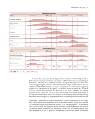
The Unified Process
Phases
Workflows
Extensions to the Unified Process
The Unified Modeling Language
Applying the Concepts at CD Selections
Summary
22.
out of thisbook, you will need to actively apply to your own systems development project
the ideas and concepts in the examples and in the “Your Turn” exercises that are presented
throughout. This book guides you through all the steps for delivering a successful informa-
tion system. Also, it illustrates how one organization (called CD Selections) applies the steps
in one project (developing a Web-based CD sales system). By the time you finish the book,
you won’t be an expert analyst, but you will be ready to start building systems for real.
This chapter first introduces the basic SDLC that IS projects follow. This life cycle is
common to all projects, although the focus and approach to each phase of the life cycle may
differ. The next section describes three fundamentally different types of systems development
methodologies: structured design, rapid application development, and agile development.
The third section describes the roles played by and the skills necessary for a systems analyst.
The final four sections introduce the fundamental characteristics of object-oriented systems,
object-oriented systems analysis and design, a specific object-oriented systems development
methodology (the Unified Process), and a specific object-oriented systems development
graphical notation (the Unified Modeling Language).
The Systems Development Life Cycle 3
A real-estate group in the federal government cospon-
sored a data warehouse with the information technology
(IT) department. In the formal proposal written by IT, costs
were estimated at $800,000, the project’s duration was
estimated to be eight months, and the responsibility for
funding was defined as the business unit’s. The IT depart-
ment proceeded with the project before it even knew if
the project had been accepted.
The project actually lasted two years because require-
ments gathering took nine months instead of one and a
half, the planned user base grew from 200 to 2,500, and
the approval process to buy technology for the project
took a year. Three weeks before technical delivery, the IT
director canceled the project. This failed endeavor cost the
organization and taxpayers $2.5 million.
Source: Hugh J. Watson et al., “Data Warehousing Failure: Case Studies
and Findings,” The Journal of Data Warehousing 4, (no. 1) (1999): 44–54.
Questions
1. Why did this system fail?
2. Why would a company spend money and time on a
project and then cancel it?
3. What could have been done to prevent this?
1–A An Expensive False Start
CONCEPTS
IN ACTION
THE SYSTEMS DEVELOPMENT LIFE CYCLE
In many ways, building an information system is similar to building a house. First, the house
(or the information system) starts with a basic idea. Second, this idea is transformed into a
simple drawing that is shown to the customer and refined (often through several drawings,
each improving on the last) until the customer agrees that the picture depicts what he or she
wants. Third, a set of blueprints is designed that presents much more detailed information
about the house (e.g., the type of water faucets, where the telephone jacks will be placed).
Finally, the house is built following the blueprints, often with some changes directed by the
customer as the house is erected.
The SDLC has a similar set of four fundamental phases: planning, analysis, design, and
implementation. Different projects might emphasize different parts of the SDLC or approach
the SDLC phases in different ways, but all projects have elements of these four phases. Each
phase is itself composed of a series of steps, which rely upon techniques that produce deliverables
(specific documents and files that provide understanding about the project).
23.
For example, inapplying for admission to a university, all students go through the
same phases: information gathering, applying, and accepting. Each of these phases has
steps; for example, information gathering includes steps such as searching for schools,
requesting information, and reading brochures. Students then use techniques (e.g., Internet
searching) that can be applied to steps (e.g., requesting information) to create deliverables
(e.g., evaluations of different aspects of universities).
In many projects, the SDLC phases and steps proceed in a logical path from start to
finish. In other projects, the project teams move through the steps consecutively, incre-
mentally, iteratively, or in other patterns. In this section, we describe the phases, the actions,
and some of the techniques that are used to accomplish the steps at a very high level. Not
all organizations follow the SDLC in exactly the same way. As we shall shortly see, there are
many variations on the overall SDLC.
For now, there are two important points to understand about the SDLC. First, you
should get a general sense of the phases and steps through which IS projects move and
some of the techniques that produce certain deliverables. Second, it is important to under-
stand that the SDLC is a process of gradual refinement. The deliverables produced in the
analysis phase provide a general idea of the shape of the new system. These deliverables are
used as input to the design phase, which then refines them to produce a set of deliverables
that describes in much more detailed terms exactly how the system will be built. These
deliverables, in turn, are used in the implementation phase to produce the actual system.
Each phase refines and elaborates on the work done previously.
Planning
The planning phase is the fundamental process of understanding why an information system
should be built and determining how the project team will go about building it.It has two steps:
1. During project initiation, the system’s business value to the organization is identified:
How will it lower costs or increase revenues? Most ideas for new systems come from
outside the IS area (e.g., from the marketing department, accounting department) in
the form of a system request. A system request presents a brief summary of a business
need, and it explains how a system that supports the need will create business value.
The IS department works together with the person or department that generated the
request (called the project sponsor) to conduct a feasibility analysis.
The feasibility analysis examines key aspects of the proposed project:
■ The idea’s technical feasibility (Can we build it?)
■ The economic feasibility (Will it provide business value?)
■ The organizational feasibility (If we build it, will it be used?)
The system request and feasibility analysis are presented to an information systems
approval committee (sometimes called a steering committee), which decides
whether the project should be undertaken.
2. Once the project is approved, it enters project management. During project man-
agement, the project manager creates a workplan, staffs the project, and puts tech-
niques in place to help the project team control and direct the project through the
entire SDLC. The deliverable for project management is a project plan, which
describes how the project team will go about developing the system.
Analysis
The analysis phase answers the questions of who will use the system, what the system will do,
and where and when it will be used. During this phase, the project team investigates any current
system(s),identifies opportunities for improvement,and develops a concept for the new system.
4 Chapter 1 Introduction to Systems Analysis and Design
24.
This phase hasthree steps:
1. An analysis strategy is developed to guide the project team’s efforts. Such a strategy
usually includes an analysis of the current system (called the as-is system) and its
problems and then ways to design a new system (called the to-be system).
2. The next step is requirements gathering (e.g., through interviews or question-
naires). The analysis of this information—in conjunction with input from the
project sponsor and many other people—leads to the development of a concept
for a new system. The system concept is then used as a basis to develop a set of
business analysis models, which describe how the business will operate if the new
system is developed. The set of models typically includes models that represent
the data and processes necessary to support the underlying business process.
3. The analyses, system concept, and models are combined into a document called
the system proposal, which is presented to the project sponsor and other key deci-
sion makers (e.g., members of the approval committee) who decide whether the
project should continue to move forward.
The system proposal is the initial deliverable that describes what business requirements the
new system should meet. Because it is really the first step in the design of the new system,
some experts argue that it is inappropriate to use the term “analysis” as the name for this
phase; some argue a better name would be “analysis and initial design.” Most organizations
continue to use the name analysis for this phase, however, so we use it in this book as well.
Just keep in mind that the deliverable from the analysis phase is both an analysis and a
high-level initial design for the new system.
Design
The design phase decides how the system will operate, in terms of the hardware, software,
and network infrastructure; the user interface, forms and reports; and the specific pro-
grams, databases, and files that will be needed. Although most of the strategic decisions
about the system were made in the development of the system concept during the analysis
phase, the steps in the design phase determine exactly how the system will operate. The
design phase has four steps:
1. The design strategy is first developed. It clarifies whether the system will be devel-
oped by the company’s own programmers, whether the system will be outsourced
to another firm (usually a consulting firm), or whether the company will buy an
existing software package.
2. This leads to the development of the basic architecture design for the system,
which describes the hardware, software, and network infrastructure to be used. In
most cases, the system will add or change the infrastructure that already exists in
the organization. The interface design specifies how the users will move through the
system (e.g., navigation methods such as menus and on-screen buttons) and the
forms and reports that the system will use.
3. The database and file specifications are developed. These define exactly what data
will be stored and where they will be stored.
4. The analyst team develops the program design, which defines the programs that
need to be written and exactly what each program will do.
This collection of deliverables (architecture design, interface design, database and file spec-
ifications, and program design) is the system specification that is handed to the programming
team for implementation. At the end of the design phase, the feasibility analysis and project
plan are reexamined and revised, and another decision is made by the project sponsor and
approval committee about whether to terminate the project or continue.
The Systems Development Life Cycle 5
25.
Implementation
The final phasein the SDLC is the implementation phase, during which the system is actu-
ally built (or purchased, in the case of a packaged software design). This is the phase that
usually gets the most attention, because for most systems it is the longest and most expen-
sive single part of the development process. This phase has three steps:
1. System construction is the first step. The system is built and tested to ensure it per-
forms as designed. Because the cost of bugs can be immense, testing is one of the
most critical steps in implementation. Most organizations give more time and
attention to testing than to writing the programs in the first place.
2. The system is installed. Installation is the process by which the old system is turned
off and the new one is turned on. It may include a direct cutover approach (in
which the new system immediately replaces the old system), a parallel conversion
approach (in which both the old and new systems are operated for a month or two
until it is clear that there are no bugs in the new system), or a phased conversion
strategy (in which the new system is installed in one part of the organization as an
initial trial and then gradually installed in others). One of the most important
aspects of conversion is the development of a training plan to teach users how to
use the new system and help manage the changes caused by the new system.
3. The analyst team establishes a support plan for the system. This plan usually
includes a formal or informal post-implementation review as well as a systematic
way for identifying major and minor changes needed for the system.
6 Chapter 1 Introduction to Systems Analysis and Design
Consumer electronics is a very competitive business.
What might be the success story of the year one year is
a forgotten item two years later. Rapid product commoditi-
zation makes the consumer electronics marketplace very
competitive. Getting the right products to market at the
right time with the right components is an ongoing chal-
lenge for telecommunications and consumer electronics
goods companies.
Questions
1. What external data analysis should a consumer
electronics company use to determine marketplace
needs and its abilities to compete effectively in a
marketplace?
2. Staying one step ahead of competitors requires a
corporate strategy and the support of information
systems. How can information systems and systems
analysts contribute to an aggressive corporate strategy?
1–B Keeping Up with Consumer Electronics
CONCEPTS
IN ACTION
SYSTEMS DEVELOPMENT METHODOLOGIES
A methodology is a formalized approach to implementing the SDLC (i.e., it is a list of steps
and deliverables). There are many different systems development methodologies, and each
one is unique, based on the order and focus it places on each SDLC phase. Some method-
ologies are formal standards used by government agencies, whereas others have been
developed by consulting firms to sell to clients. Many organizations have internal method-
ologies that have been honed over the years, and they explain exactly how each phase of
the SDLC is to be performed in that company.
There are many ways to categorize methodologies. One way is by looking at whether
they focus on business processes or the data that support the business. A process-centered
26.
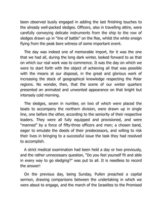
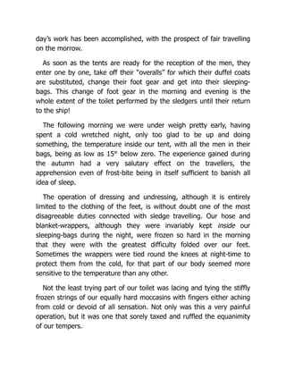
methodology emphasizes processmodels as the core of the system concept. In Figure 1-1,
for example, process-centered methodologies would focus first on defining the processes
(e.g., assemble sandwich ingredients). Data-centered methodologies emphasize data mod-
els as the core of the system concept. In Figure 1-1, data-centered methodologies would
focus first on defining the contents of the storage areas (e.g., refrigerator) and how the con-
tents were organized.2 By contrast, object-oriented methodologies attempt to balance the
focus between process and data by incorporating both into one model. In Figure 1-1, these
Systems Development Methodologies 7
2 The classic modern process-centered methodology is that by Edward Yourdon, Modern Structured Analysis
(Englewood Cliffs, NJ: Yourdon Press, 1989). An example of a data-centered methodology is information engi-
neering; see James Martin, Information Engineering, vols. 1–3 (Englewood Cliffs, NJ: Prentice Hall, 1989). A
widely accepted standardized non–object-oriented methodology that balances processes and data is IDEF; see
FIPS 183, Integration Definition for Function Modeling, Federal Information Processing Standards Publications,
U.S. Department of Commerce, 1993.
GetJelly
GetPeanutButter
GetCookies
GetBread
CreateSandwich
GetMilk
CreateLunch
GetLunchBag
PutLunchInBag
aParent aRefrigerator aCupboard aSandwich aLunch aLunchBag
FIGURE 1-1 A Simple Behavioral Model for Making a Simple Lunch
27.
methodologies would focusfirst on defining the major elements of the system (e.g., sand-
wiches, lunches) and look at the processes and data involved with each element.
Another important factor in categorizing methodologies is the sequencing of the
SDLC phases and the amount of time and effort devoted to each.3 In the early days of com-
puting, programmers did not understand the need for formal and well-planned life-cycle
methodologies. They tended to move directly from a very simple planning phase right into
the construction step of the implementation phase—in other words, from a very fuzzy,
not-well-thought-out system request into writing code. This is the same approach that you
sometimes use when writing programs for a programming class. It can work for small pro-
grams that require only one programmer, but if the requirements are complex or unclear,
you might miss important aspects of the problem and have to start all over again, throw-
ing away part of the program (and the time and effort spent writing it). This approach also
makes teamwork difficult because members have little idea about what needs to be accom-
plished and how to work together to produce a final product. In this section, we describe
three different classes of system development methodologies: structured design, rapid
application development, and agile development.
Structured Design
The first category of systems development methodologies is called structured design. These
methodologies became dominant in the 1980s, replacing the previous ad hoc and undisci-
plined approach. Structured design methodologies adopt a formal step-by-step approach
to the SDLC that moves logically from one phase to the next. Numerous process-centered
and data-centered methodologies follow the basic approach of the two structured design
categories outlined next.
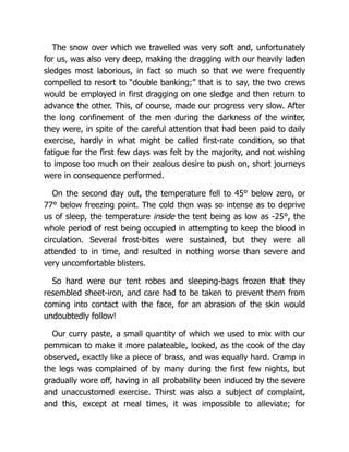
Waterfall Development The original structured design methodology (still used today)
is waterfall development. With waterfall development–based methodologies, the analysts
and users proceed in sequence from one phase to the next (see Figure 1-2). The key deliv-
erables for each phase are typically very long (often hundreds of pages in length) and are
presented to the project sponsor for approval as the project moves from phase to phase.
Once the sponsor approves the work that was conducted for a phase, the phase ends and
the next one begins. This methodology is referred to as waterfall development because it
moves forward from phase to phase in the same manner as a waterfall. Although it is pos-
sible to go backward in the SDLC (e.g., from design back to analysis), it is extremely diffi-
cult (imagine yourself as a salmon trying to swim upstream against a waterfall, as shown
in Figure 1-2).
Structured design also introduced the use of formal modeling or diagramming tech-
niques to describe the basic business processes and the data that support them. Traditional
structured design uses one set of diagrams to represent the processes and a separate set of
diagrams to represent data. Because two sets of diagrams are used, the systems analyst must
decide which set to develop first and use as the core of the system: process-model diagrams
or data-model diagrams. There is much debate over which should come first, the processes
or the data, because both are important to the system. As a result, several different struc-
tured design methodologies have evolved that follow the basic steps of the waterfall model
but use different modeling approaches at different times. Those that attempt to emphasize
process-model diagrams as the core of the system are process centered, whereas those that
emphasize data-model diagrams as the core of the system concept are data centered.
8 Chapter 1 Introduction to Systems Analysis and Design
3 A good reference for comparing systems development methodologies is Steve McConnell, Rapid Development
(Redmond, WA: Microsoft Press, 1996).
28.
The two keyadvantages of the structured design waterfall approach are that it identifies
system requirements long before programming begins and it minimizes changes to the
requirements as the project proceeds. The two key disadvantages are that the design must
be completely specified before programming begins and that a long time elapses between
the completion of the system proposal in the analysis phase and the delivery of the system
(usually many months or years). Lengthy deliverables often result in poor communication;
the result is that important requirements can be overlooked in the voluminous documenta-
tion. Users are rarely prepared for their introduction to the new system, which occurs long
after the initial idea for the system was introduced. If the project team misses important
requirements, expensive post-implementation programming may be needed (imagine your-
self trying to design a car on paper; how likely would you be to remember interior lights that
come on when the doors open or to specify the right number of valves on the engine?).
A system can also require significant rework because the business environment has
changed from the time that the analysis phase occurred. When changes do occur, it means
going back to the initial phases and following the change through each of the subsequent
phases in turn.
Parallel Development Parallel development methodology attempts to address the prob-
lem of long delays between the analysis phase and the delivery of the system. Instead of
doing design and implementation in sequence, it performs a general design for the whole
system and then divides the project into a series of distinct subprojects that can be designed
and implemented in parallel. Once all subprojects are complete, the separate pieces are
integrated and the system is delivered (see Figure 1-3).
The primary advantage of this methodology is that it can reduce the time to deliver
a system; thus, there is less chance of changes in the business environment causing rework.
However, the approach still suffers from problems caused by paper documents. It also
adds a new problem: Sometimes the subprojects are not completely independent; design
decisions made in one subproject can affect another, and the end of the project can
require significant integration efforts.
Systems Development Methodologies 9
System
Planning
Analysis
Design
Implementation
FIGURE 1-2
A Waterfall
Development–based
Methodology
29.
Rapid Application Development(RAD)
A second category of methodologies includes rapid application development (RAD)-based
methodologies. These are a newer class of systems development methodologies that
emerged in the 1990s. RAD-based methodologies attempt to address both weaknesses of
structured design methodologies by adjusting the SDLC phases to get some part of the
system developed quickly and into the hands of the users. In this way, the users can better
understand the system and suggest revisions that bring the system closer to what is
needed.4
Most RAD-based methodologies recommend that analysts use special techniques and
computer tools to speed up the analysis, design, and implementation phases, such as com-
puter-aided software engineering (CASE) tools, joint application design (JAD) sessions,
fourth-generation or visual programming languages that simplify and speed up program-
ming (e.g., Visual Basic), and code generators that automatically produce programs from
design specifications. The combination of the changed SDLC phases and the use of these
tools and techniques improves the speed and quality of systems development. However,
there is one possible subtle problem with RAD-based methodologies: managing user expec-
tations. Owing to the use of the tools and techniques that can improve the speed and quality
of systems development, user expectations of what is possible can change dramatically. As a
1
10
0 C
Chapter 1
1 Introduction to Systems Analysis and Design
4 One of the best RAD books is Steve McConnell, Rapid Development (Redmond, WA: Microsoft Press, 1996).
System
Planning
Analysis
Design
Implementation
Design
Integration
Implementation
Design
Implementation
Design
Subproject 2
Subproject 1
Subproject 3
F
FIGURE 1
1-3 A Parallel Development-based Methodology
30.
user better understandsthe information technology (IT), the systems requirements tend to
expand. This was less of a problem when using methodologies that spent a lot of time thor-
oughly documenting requirements. Process-centered, data-centered, and object-oriented
methodologies that follow the basic approaches of the three RAD categories are described
in the following sections.
Phased Development A phased development-based methodology breaks an overall system
into a series of versions that are developed sequentially. The analysis phase identifies the
overall system concept, and the project team, users, and system sponsor then categorize the
requirements into a series of versions. The most important and fundamental requirements
are bundled into the first version of the system. The analysis phase then leads into design
and implementation—but only with the set of requirements identified for version 1 (see
Figure 1-4).
Once version 1 is implemented, work begins on version 2. Additional analysis is per-
formed based on the previously identified requirements and combined with new ideas and
Systems Development Methodologies 1
11
System
version 1
Planning
Analysis
Analysis
Implementation
Design
Analysis
Implementation
Design
Analysis
Implementation
Design
System
version 2
System
version 3
F
FIGURE 1
1-4 A Phased Development-based Methodology
31.
issues that arosefrom the users’ experience with version 1. Version 2 then is designed and
implemented, and work immediately begins on the next version. This process continues
until the system is complete or is no longer in use.
Phased development–based methodologies have the advantage of quickly getting a
useful system into the hands of the users. Although the system does not perform all the
functions the users need at first, it does begin to provide business value sooner than if the
system were delivered after completion, as is the case with the waterfall and parallel
methodologies. Likewise, because users begin to work with the system sooner, they are
more likely to identify important additional requirements sooner than with structured
design situations.
The major drawback to phased development is that users begin to work with systems
that are intentionally incomplete. It is critical to identify the most important and useful
features and include them in the first version and to manage users’ expectations along the
way.
Prototyping A prototyping-based methodology performs the analysis, design, and imple-
mentation phases concurrently, and all three phases are performed repeatedly in a cycle
until the system is completed. With these methodologies, the basics of analysis and design
are performed, and work immediately begins on a system prototype, a quick-and-dirty pro-
gram that provides a minimal amount of features. The first prototype is usually the first
part of the system that is used. This is shown to the users and the project sponsor, who
provide comments. These comments are used to reanalyze, redesign, and re-implement a
second prototype, which provides a few more features. This process continues in a cycle
until the analysts, users, and sponsor agree that the prototype provides enough functionality
to be installed and used in the organization. After the prototype (now called the “system”) is
installed, refinement occurs until it is accepted as the new system (see Figure 1-5).
The key advantage of a prototyping-based methodology is that it very quickly provides
a system with which the users can interact, even if it is not ready for widespread organiza-
tional use at first. Prototyping reassures the users that the project team is working on the
system (there are no long delays in which the users see little progress), and prototyping
helps to more quickly refine real requirements. Rather than attempting to understand a sys-
tem specification on paper, the users can interact with the prototype to better understand
what it can and cannot do.
The major problem with prototyping is that its fast-paced system releases challenge
attempts to conduct careful, methodical analysis. Often the prototype undergoes such
significant changes that many initial design decisions become poor ones. This can cause
12 Chapter 1 Introduction to Systems Analysis and Design
System
prototype
System
Planning
Analysis
Design
Implementation
Implementation
FIGURE 1-5
A Prototyping-based
Methodology
32.
problems in thedevelopment of complex systems because fundamental issues and prob-
lems are not recognized until well into the development process. Imagine building a car
and discovering late in the prototyping process that you have to take the whole engine out
to change the oil (because no one thought about the need to change the oil until after it had
been driven 10,000 miles).
Throwaway Prototyping Throwaway prototyping-based methodologies are similar to
prototyping-based methodologies in that they include the development of prototypes;
however, throwaway prototypes are done at a different point in the SDLC. These prototypes
are used for a very different purpose than those previously discussed, and they have a very
different appearance (see Figure 1-6).
The throwaway prototyping–based methodologies have a relatively thorough analysis
phase that is used to gather information and to develop ideas for the system concept. How-
ever, users might not completely understand many of the features they suggest, and there
may be challenging technical issues to be solved. Each of these issues is examined by ana-
lyzing, designing, and building a design prototype. A design prototype is not a working
system; it is a product that represents a part of the system that needs additional refinement,
and it contains only enough detail to enable users to understand the issues under consid-
eration. For example, suppose users are not completely clear on how an order-entry system
should work. The analyst team might build a series of HTML pages viewed using a Web
browser to help the users visualize such a system. In this case, a series of mock-up screens
appear to be a system, but they really do nothing. Or suppose that the project team needs
to develop a sophisticated graphics program in Java. The team could write a portion of the
program with pretend data to ensure that they could do a full-blown program successfully.
A system developed using this type of methodology probably relies on several design
prototypes during the analysis and design phases. Each of the prototypes is used to mini-
mize the risk associated with the system by confirming that important issues are under-
stood before the real system is built. Once the issues are resolved, the project moves into
design and implementation. At this point, the design prototypes are thrown away, which is
an important difference between these methodologies and prototyping methodologies, in
which the prototypes evolve into the final system.
Systems Development Methodologies 1
13
Design
prototype
System
Analysis
Analysis
Design
Implementation
Planning
Implementation
Design
FIGURE 1
1-6 A Throwaway Prototyping–based Methodology
33.
Throwaway prototyping-based methodologiesbalance the benefits of well-thought-
out analysis and design phases with the advantages of using prototypes to refine key issues
before a system is built. It can take longer to deliver the final system as compared to proto-
typing-based methodologies (because the prototypes do not become the final system), but
this type of methodology usually produces more stable and reliable systems.
Agile Development5
A third category of systems development methodologies is still emerging today: agile devel-
opment. All agile development methodologies are based on the agile manifesto and a set of
twelve principles. The emphasis of the manifesto is to focus the developers on the working
conditions of the developers, the working software, the customers, and addressing chang-
ing requirements instead of focusing on detailed systems development processes, tools, all-
inclusive documentation, legal contracts, and detailed plans. These programming-centric
methodologies have few rules and practices, all of which are fairly easy to follow. These
methodologies are typically based only on the twelve principles of agile software. These
principles include the following:
■ Software is delivered early and continuously through the development process,
satisfying the customer.
■ Changing requirements are embraced regardless of when they occur in the devel-
opment process.
■ Working software is delivered frequently to the customer.
■ Customers and developers work together to solve the business problem.
■ Motivated individuals create solutions; provide them the tools and environment
they need and trust them to deliver.
■ Face-to-face communication within the development team is the most efficient
and effective method of gathering requirements.
■ The primary measure of progress is working, executing software.
■ Both customers and developers should work at a pace that is sustainable. That is,
the level of work could be maintained indefinitely without any worker burnout.
■ Agility is heightened through attention to both technical excellence and good design.
■ Simplicity, the avoidance of unnecessary work, is essential.
■ Self-organizing teams develop the best architectures, requirements, and designs.
■ Development teams regularly reflect on how to improve their development
processes.
Based on these principles, agile methodologies focus on streamlining the system-development
process by eliminating much of the modeling and documentation overhead and the time
spent on those tasks. Instead, projects emphasize simple, iterative application development.6
All agile development methodologies follow a simple cycle through the traditional phases
of the systems development process (see Figure 1-7). Virtually all agile methodologies are
used in conjunction with object-oriented technologies.
However, agile methodologies do have critics. One of the major criticisms deals with
today’s business environment, where much of the actual information systems development
1
14
4 C
Chapter 1
1 Introduction to Systems Analysis and Design
5 Three good sources of information on agile development and object-oriented systems are S. W. Ambler, Agile
Modeling: Effective Practices for Extreme Programming and The Unified Process (New York: Wiley, 2002); C.
Larman, Agile & Iterative Development: A Manager’s Guide (Boston: Addison-Wesley, 2004); and R. C. Martin,
Agile Software Development: Principles, Patterns, and Practices (Upper Saddle River, NJ: Prentice Hall, 2003).
6 See www.agilealliance.com.
34.
is offshored, outsourced,and/or subcontracted. Given agile development methodologies
requiring co-location of the development team, this seems to be a very unrealistic assump-
tion. A second major criticism is that if agile development is not carefully managed, and by
definition it is not, the development process can devolve into a prototyping approach that
essentially becomes a “programmers gone wild” environment where programmers attempt
to hack together solutions. A third major criticism, based on the lack of actual documen-
tation created during the development of the software, raises issues regarding the auditability
of the systems being created. Without sufficient documentation, neither the system nor the
systems-development process can be assured. A fourth major criticism is based on whether
agile approaches can deliver large mission-critical systems.
Even with these criticisms, given the potential for agile approaches to address
the application backlog and to provide timely solutions to many business problems,
agile approaches should be considered in some circumstances. Furthermore, many of
the techniques encouraged by attending to the underlying purpose of the agile mani-
festo and the set of twelve agile principles are very useful in object-oriented systems
development. Two of the more popular examples of agile development methodologies
are extreme programming (XP) and Scrum. We describe both of these methodologies
in the next two sections.
Extreme Programming7 Extreme programming (XP) is founded on four core values:
communication, simplicity, feedback, and courage. These four values provide a foundation
that XP developers use to create any system. First, the developers must provide rapid feed-
back to the end users on a continuous basis. Second, XP requires developers to follow the
KISS principle.8 Third, developers must make incremental changes to grow the system, and
they must not only accept change, they must embrace change. Fourth, developers must
have a quality-first mentality. XP also supports team members in developing their own
skills. Three of the key principles that XP uses to create successful systems are continuous
testing, simple coding performed by pairs of developers, and close interactions with end
users to build systems very quickly.
Testing and efficient coding practices are the core of XP. Code is tested each day and
is placed into an integrative testing environment. If bugs exist, the code is backed out until
Systems Development Methodologies 15
Implementation
Design
Analysis
System
Planning
FIGURE 1-7
Typical Agile
Development
Methodology
7 For more information, see K. Beck, eXtreme Programming Explained: Embrace Change (Reading, MA: Addison-
Wesley, 2000), C. Larman, Agile & Iterative Development: A Manager’s Guide (Boston: Addison-Wesley, 2004), M.
Lippert, S. Roock, and H. Wolf, eXtreme Programming in Action: Practical Experiences from Real World Projects
(New York: Wiley, 2002), or www.extremeprogramming.com.
8 Keep it simple, stupid.
35.
it is completelyfree of errors. XP relies heavily on refactoring, which is a disciplined way
to restructure code to keep it simple.
An XP project begins with user stories that describe what the system needs to do.
Then, programmers code in small, simple modules and test to meet those needs. Users are
required to be available to clear up questions and issues as they arise. Standards are very
important to minimize confusion, so XP teams use a common set of names, descriptions,
and coding practices. XP projects deliver results sooner than even the RAD approaches, and
they rarely get bogged down in gathering requirements for the system.
XP adherents claim many strengths associated with developing software using XP.
Programmers work closely with all stakeholders, and communication among all stake-
holders is improved. Continuous testing of the evolving system is encouraged. The system
is developed in an evolutionary and incremental manner, which allows the requirements
to evolve as the stakeholders understand the potential that the technology has in provid-
ing a solution to their problem. Estimation is task driven and is performed by the pro-
grammer who will implement the solution for the task under consideration. Because all
programming is done in pairs, a shared responsibility for each software component devel-
ops among the programmers. Finally, the quality of the final product increases during
each iteration.
For small projects with highly motivated, cohesive, stable, and experienced teams, XP
should work just fine. However, if the project is not small or the teams aren’t jelled,9 the
success of an XP development effort is doubtful. This tends to throw into doubt the whole
idea of bringing outside contractors into an existing team environment using XP.10 The
chance of outsiders jelling with insiders might simply be too optimistic. XP requires a great
deal of discipline; otherwise projects will become unfocused and chaotic. XP it is recom-
mended only for small groups of developers—no more than ten developers—and it is not
advised for large mission-critical applications. Owing to the lack of analysis and design
documentation, there is only code documentation associated with XP, so maintaining large
systems built with XP may be impossible. And because mission-critical business informa-
tion systems tend to exist for a long time, the utility of XP as a business information sys-
tem development methodology is in doubt. Finally, the methodology needs a lot of on-site
user input, something to which many business units cannot commit.11 However, some of
the techniques associated with XP are useful in object-oriented systems development. For
example, user stories, pair programming, and continuous testing are invaluable tools from
which object-oriented systems development could benefit.
Scrum12 Scrum is a term that is well known to rugby fans. In rugby, a scrum is used to
restart a game (see Figure 1-8). In a nutshell, the creators of the Scrum method believe that
no matter how much you plan, as soon as the software begins to be developed, chaos breaks
16 Chapter 1 Introduction to Systems Analysis and Design
9 A jelled team is one that has low turnover, a strong sense of identity, a sense of eliteness, a feeling that they jointly
own the product being developed, and enjoyment in working together. For more information regarding jelled
teams, see T. DeMarco and T. Lister, Peopleware: Productive Projects and Teams (New York: Dorset/House, 1987).
10 Considering the tendency for offshore outsourcing, this is a major obstacle for XP to overcome. For more infor-
mation on offshore outsourcing, see P. Thibodeau,“ITAA Panel Debates Outsourcing Pros, Cons,” Computerworld
Morning Update (September 25, 2003), and S. W. Ambler, “Chicken Little Was Right,” Software Development
(October 2003).
11 Many of the observations on the utility of XP as a development approach were based on conversations with
Brian Henderson-Sellers.
12 For more information see C. Larman, Agile & Iterative Development: A Manager’s Guide (Boston: Addison-
Wesley, 2004), K. Schwaber and M. Beedle, Agile Software Development with Scrum (Upper Saddle River,
NJ: Prentice Hall, 2001), and R. Wysocki, Effective Project Management: Traditional, Agile, Extreme, 5th Ed.
(Indianapolis, IN: Wiley Publishing, 2009).
36.
out and theplans go out the window.13 The best you can do is to react to where the prover-
bial rugby ball squirts out. You then sprint with the ball until the next scrum. In the case of
the Scrum methodology, a sprint lasts thirty working days. At the end of the sprint, a system
is delivered to the customer.
Of all systems development approaches, on the surface, Scrum is the most chaotic. To
control some of the innate chaos, Scrum development focuses on a few key practices. Teams
are self-organized and self-directed. Unlike other approaches, Scrum teams do not have a
designated team leader. Instead, teams organize themselves in a symbiotic manner and set
their own goals for each sprint (iteration). Once a sprint has begun, Scrum teams do not
consider any additional requirements. Any new requirements that are uncovered are placed
on a backlog of requirements that still need to be addressed.At the beginning of every work-
day, a Scrum meeting takes place. At the end of each sprint, the team demonstrates the soft-
ware to the client. Based on the results of the sprint, a new plan is begun for the next sprint.
Scrum meetings are one of the most interesting aspects of the Scrum development
process. The team members attend the meetings, but anyone can attend. However, with
very few exceptions, only team members may speak. One prominent exception is manage-
ment providing feedback on the business relevance of the work being performed by the
specific team. In this meeting, all team members stand in a circle and report on what they
accomplished during the previous day, state what they plan to do today, and describe any-
thing that blocked progress the previous day. To enable continuous progress, any block
identified is dealt with within one hour. From a Scrum point of view, it is better to make a
“bad” decision about a block at this point in development than to not make a decision.
Because the meetings take place each day, a bad decision can easily be undone. Larman14
suggests that each team member should report any additional requirements that have been
uncovered during the sprint and anything that the team member learned that could be use-
ful for other team members to know.
Systems Development Methodologies 1
17
F
FIGURE 1
1-8
Rugby Scrum
(Rugby Game)
(Source: Alan Brooke/Image
Source)
13 Scrum developers are not the first to question the use of plans. One of President Eisenhower’s favorite maxims
was,“In preparing for battle I have always found that plans are useless, but planning is indispensable.” M. Dobson,
Streetwise Project Management: How to Manage People, Processes, and Time to Achieve the Results You Need (Avon,
MA: FW Publications, 2003) p. 43.
14 C. Larman, Agile Iterative Development: A Manager’s Guide (Boston: Addison-Wesley, 2004).
37.
One of themajor criticisms of Scrum, as with all agile methodologies, is that it is ques-
tionable whether Scrum can scale up to develop very large, mission-critical systems. A typ-
ical Scrum team size is no more than seven members. The only organizing principle put
forth by Scrum followers to address this criticism is to organize a scrum of scrums. Each
team meets every day, and after the team meeting takes place, a representative (not leader)
of each team attends a scrum-of-scrums meeting. This continues until the progress of
entire system has been determined. Depending on the number of teams involved, this
approach to managing a large project is doubtful. However, as in XP and other agile devel-
opment approaches, many of the ideas and techniques associated with Scrum development
are useful in object-oriented systems development, such as the focus of a Scrum meeting,
the evolutionary and incremental approach to identifying requirements, and the incre-
mental and iterative approach to the development of the system.
Selecting the Appropriate Development Methodology
Because there are many methodologies, the first challenge faced by analysts is selecting
which methodology to use. Choosing a methodology is not simple, because no one
methodology is always best. (If it were, we’d simply use it everywhere!) Many organizations
have standards and policies to guide the choice of methodology. You will find that organi-
zations range from having one “approved” methodology to having several methodology
options to having no formal policies at all.
Figure 1-9 summarizes some important criteria for selecting a methodology. One
important item not discussed in this figure is the degree of experience of the analyst team.
Many of the RAD-based methodologies require the use of new tools and techniques that
have a significant learning curve. Often these tools and techniques increase the complexity
of the project and require extra time for learning. However, once they are adopted and the
team becomes experienced, the tools and techniques can significantly increase the speed at
which the methodology can deliver a final system.
Clarity of User Requirements When the user requirements for a system are unclear, it
is difficult to understand them by talking about them and explaining them with written
reports. Users normally need to interact with technology to really understand what a new
system can do and how to best apply it to their needs. RAD and agile methodologies are
usually more appropriate when user requirements are unclear.
18 Chapter 1 Introduction to Systems Analysis and Design
With Unclear User Requirements Poor Poor Good Excellent Excellent Excellent Excellent
With Unfamiliar Technology Poor Poor Good Poor Excellent Good Good
That Are Complex Good Good Good Poor Excellent Good Good
That Are Reliable Good Good Good Poor Excellent Excellent Excellent
With a Short Time Schedule Poor Good Excellent Excellent Good Excellent Excellent
With Schedule Visibility Poor Poor Excellent Excellent Good Excellent Excellent
Structured Agile
Methodologies RAD Methodologies Methodologies
Ability to Develop Throwaway
Systems Waterfall Parallel Phased Prototyping Prototyping XP SCRUM
FIGURE 1-9 Criteria for Selecting a Methodology
38.
Familiarity with TechnologyWhen the system will use new technology with which the
analysts and programmers are not familiar (e.g., the first Web development project with
Java), early application of the new technology in the methodology will improve the chance
of success. If the system is designed without some familiarity with the base technology,
risks increase because the tools might not be capable of doing what is needed. Throwaway
prototyping–based methodologies are particularly appropriate if users lack familiarity with
technology because they explicitly encourage the developers to develop design prototypes for
areas with high risks. Phased development–based methodologies are good as well, because
they create opportunities to investigate the technology in some depth before the design is
complete. Also, owing to the programming-centric nature of agile methodologies, both XP
and Scrum are appropriate. Although you might think prototyping-based methodologies are
also appropriate, they are much less so because the early prototypes that are built usually only
scratch the surface of the new technology. It is generally only after several prototypes and sev-
eral months that the developers discover weaknesses or problems in the new technology.
System Complexity Complex systems require careful and detailed analysis and design.
Throwaway prototyping–based methodologies are particularly well suited to such detailed
analysis and design, but prototyping-based methodologies are not. The traditional struc-
tured design–based methodologies can handle complex systems, but without the ability to
get the system or prototypes into the users’ hands early on, some key issues may be over-
looked. Although phased development–based methodologies enable users to interact with
the system early in the process, we have observed that project teams who follow these tend
to devote less attention to the analysis of the complete problem domain than they might
using other methodologies. Finally, agile methodologies are a mixed bag when it comes to
system complexity. If the system is going to be a large one, then, owing to the lack of formal
project management techniques used, agile methodologies will perform poorly. However,
if the system is small to medium size, then agile approaches will be excellent. We rate them
good on these criteria.
System Reliability System reliability is usually an important factor in system develop-
ment; after all, who wants an unreliable system? However, reliability is just one factor
among several. For some applications, reliability is truly critical (e.g., medical equipment,
missile-control systems), whereas for other applications (e.g., games, Internet video) it is
merely important. Because throwaway prototyping methodologies combine detailed analysis
and design phases with the ability for the project team to test many different approaches
through design prototypes before completing the design, they are appropriate when system
reliability is a high priority. Prototyping methodologies are generally not a good choice
when reliability is critical because it lacks the careful analysis and design phases that are
essential for dependable systems. However, owing to the heavy focus on testing, evolution-
ary and incremental identification of requirements, and iterative and incremental develop-
ment, agile methods may be the best overall approach.
Short Time Schedules Projects that have short time schedules are well suited for RAD-
based and agile methodologies because these methodologies are designed to increase the
speed of development. RAD-based and agile methodologies are excellent choices when
timelines are short because they best enable the project team to adjust the functionality in
the system based on a specific delivery date, and if the project schedule starts to slip, it can
be readjusted by removing functionality from the version or prototype under development.
Waterfall-based methodologies are the worst choice when time is at a premium because
they do not allow easy schedule changes.
Systems Development Methodologies 19
39.
Schedule Visibility Oneof the greatest challenges in systems development is determin-
ing whether a project is on schedule. This is particularly true of the structured design
methodologies because design and implementation occur at the end of the project. The
RAD-based methodologies move many of the critical design decisions earlier in the project
to help project managers recognize and address risk factors and keep expectations in check.
However, given the daily progress meetings associated with Agile approaches, schedule
visibility is always on the proverbial front burner.
2
20
0 C
Chapter 1
1 Introduction to Systems Analysis and Design
S
Suppose you are an analyst for the Roanoke Software
Consulting Company (RSCC), a large consulting firm
with offices around the world. The company wants to
build a new knowledge management system that can
identify and track the expertise of individual consultants
anywhere in the world based on their education and the
various consulting projects on which they have worked.
Assume that this is a new idea that has never before
been attempted in RSCC or elsewhere. RSCC has an
international network, but the offices in each country
may use somewhat different hardware and software.
RSCC management wants the system up and running
within a year.
Question
1. What type of methodology would you recommend
that RSCC use? Why?
1-1
1 Selecting a
a M
Methodology
YOUR
R
TURN
TYPICAL SYSTEMS ANALYST ROLES AND SKILLS
It is clear from the various phases and steps performed during the SDLC that the project
team needs a variety of skills. Project members are change agents who identify ways to
improve an organization, build an information system to support them, and train and
motivate others to use the system. Leading a successful organizational change effort is one
of the most difficult jobs that someone can do. Understanding what to change and how to
change it—and convincing others of the need for change—requires a wide range of skills.
These skills can be broken down into six major categories: technical, business, analytical,
interpersonal, management, and ethical.
Analysts must have the technical skills to understand the organization’s existing tech-
nical environment, the technology that will make up the new system, and the way both can
fit into an integrated technical solution. Business skills are required to understand how IT
can be applied to business situations and to ensure that the IT delivers real business value.
Analysts are continuous problem solvers at both the project and the organizational level,
and they put their analytical skills to the test regularly.
Analysts often need to communicate effectively one-on-one with users and business
managers (who often have little experience with technology) and with programmers (who
often have more technical expertise than the analyst).They must be able to give presentations
to large and small groups and write reports. Not only do they need to have strong interper-
sonal abilities, but they also need to manage people with whom they work and they need to
manage the pressure and risks associated with unclear situations.
Finally, analysts must deal fairly, honestly, and ethically with other project team mem-
bers, managers, and system users. Analysts often deal with confidential information or
information that, if shared with others, could cause harm (e.g., dissent among employees);
it is important to maintain confidence and trust with all people.
40.
In addition tothese six general skill sets, analysts require many specific skills associated
with roles performed on a project. In the early days of systems development, most organi-
zations expected one person, the analyst, to have all the specific skills needed to conduct a
systems development project. Some small organizations still expect one person to perform
many roles, but because organizations and technology have become more complex, most
large organizations now build project teams containing several individuals with clearly
defined responsibilities. Different organizations divide the roles differently, but Figure 1-10
presents one commonly used set of project team roles. Most IS teams include many other
individuals, such as the programmers, who actually write the programs that make up the
system, and technical writers, who prepare the help screens and other documentation (e.g.,
users manuals and systems manuals).
Business Analyst
A business analyst focuses on the business issues surrounding the system. These issues include
identifying the business value that the system will create, developing ideas and suggestions for
how the business processes can be improved, and designing the new processes and policies in
conjunction with the systems analyst. This individual likely has business experience and some
type of professional training (e.g., the business analyst for accounting systems is likely a CPA
[in the United States] or a CA [in Canada]). He or she represents the interests of the project
sponsor and the ultimate users of the system. A business analyst assists in the planning and
design phases but is most active in the analysis phase.
Systems Analyst
A systems analyst focuses on the IS issues surrounding the system. This person develops
ideas and suggestions for how information technology can improve business processes,
designs the new business processes with help from the business analyst, designs the new
information system, and ensures that all IS standards are maintained. A systems analyst
Typical Systems Analyst Roles and Skills 21
Business analyst Analyzing the key business aspects of the system
Identifying how the system will provide business value
Designing the new business processes and policies
Systems analyst Identifying how technology can improve business processes
Designing the new business processes
Designing the information system
Ensuring that the system conforms to information systems standards
Infrastructure analyst Ensuring the system conforms to infrastructure standards
Identifying infrastructure changes needed to support the system
Change management analyst Developing and executing a change management plan
Developing and executing a user training plan
Project manager Managing the team of analysts, programmers, technical writers, and
other specialists
Developing and monitoring the project plan
Assigning resources
Serving as the primary point of contact for the project
Role Responsibilities
FIGURE 1-10
Project Team Roles
41.
likely has significanttraining and experience in analysis and design, programming, and even
areas of the business. He or she represents the interests of the IS department and works
intensively through the project but perhaps less so during the implementation phase.
Infrastructure Analyst
An infrastructure analyst focuses on the technical issues surrounding how the system will
interact with the organization’s technical infrastructure (e.g., hardware, software, net-
works, and databases). An infrastructure analyst’s tasks include ensuring that the new
information system conforms to organizational standards and identifying infrastructure
changes needed to support the system. This individual probably has significant training
and experience in networking, database administration, and various hardware and soft-
ware products. He or she represents the interests of the organization and IS group that will
ultimately have to operate and support the new system once it has been installed. An
infrastructure analyst works throughout the project but perhaps less so during planning
and analysis phases.
Change Management Analyst
A change management analyst focuses on the people and management issues surrounding
the system installation. The roles of this person include ensuring that the adequate docu-
mentation and support are available to users, providing user training on the new system,
and developing strategies to overcome resistance to change. This individual should have
significant training and experience in organizational behavior in general and change man-
agement in particular. He or she represents the interests of the project sponsor and users
for whom the system is being designed. A change management analyst works most actively
during the implementation phase but begins laying the groundwork for change during the
analysis and design phases.
Project Manager
A project manager is responsible for ensuring that the project is completed on time and
within budget and that the system delivers all benefits intended by the project sponsor. The
role of the project manager includes managing the team members, developing the project
plan, assigning resources, and being the primary point of contact when people outside the
team have questions about the project. This individual likely has significant experience in
project management and has probably worked for many years as a systems analyst before-
hand. He or she represents the interests of the IS department and the project sponsor. The
project manager works intensely during all phases of the project.
22 Chapter 1 Introduction to Systems Analysis and Design
Suppose you decide to become an analyst after you grad-
uate. Decide what type of analyst you would prefer to be
and what types of courses you should take before you
graduate. Then decide the type of summer job or intern-
ship you should seek.
Question
Develop a short plan that describes how you will prepare
for your career as an analyst.
1-2 Being an Analyst
YOUR
TURN
42.
BASIC CHARACTERISTICS OFOBJECT-ORIENTED SYSTEMS
Object-oriented systems focus on capturing the structure and behavior of information sys-
tems in little modules that encompass both data and process. These little modules are
known as objects. In this section, we describe the basic characteristics of object-oriented
systems, which include classes, objects, methods, messages, encapsulation, information
hiding, inheritance, polymorphism, and dynamic binding.15
Classes and Objects
A class is the general template we use to define and create specific instances, or objects. Every
object is associated with a class. For example, all the objects that capture information about
patients could fall into a class called Patient, because there are attributes (e.g., name, address,
birth date, phone, and insurance carrier) and methods (e.g., make appointment, calculate last
visit, change status, and provide medical history) that all patients share (see Figure 1-11).
An object is an instantiation of a class. In other words, an object is a person, place, or
thing about which we want to capture information. If we were building an appointment
system for a doctor’s office, classes might include Doctor, Patient, and Appointment. The
specific patients, such as Jim Maloney, Mary Wilson, and Theresa Marks, are considered
instances, or objects, of the patient class (see Figure 1-11).
Each object has attributes that describe information about the object, such as a
patient’s name, birth date, address, and phone number. Attributes are also used to repre-
sent relationships between objects; for example, there could be a department attribute in
an employee object with a value of a department object that captures in which department
the employee object works. The state of an object is defined by the value of its attributes
and its relationships with other objects at a particular point in time. For example, a patient
might have a state of new or current or former.
Each object also has behaviors. The behaviors specify what the object can do. For
example, an appointment object can probably schedule a new appointment, delete an
appointment, and locate the next available appointment. In object-oriented programming,
behaviors are implemented as methods (see the next section).
Basic Characteristics of Object-Oriented Systems 23
15 In Chapter 8, we review the basic characteristics of object-oriented systems in more detail.
Patient
-name
-address
-birthdate
-phone
-insurance carrier
+make appointment()
+calculate last visit()
+change status()
+provides medical history()
+create()
Mary Wilson : Patient
Jim Maloney : Patient Theresa Marks : Patient
FIGURE 1-11
Classes and Objects
43.
One of themore confusing aspects of object-oriented systems development is the fact
that in most object-oriented programming languages, both classes and instances of classes
can have attributes and methods. Class attributes and methods tend to be used to model
attributes (or methods) that deal with issues related to all instances of the class. For example,
to create a new patient object, a message is sent to the Patient class to create a new instance
of itself. However, in this book, we focus primarily on attributes and methods of objects
and not of classes.
Methods and Messages
Methods implement an object’s behavior. A method is nothing more than an action that an
object can perform. As such, a method is analogous to a function or procedure in a tradi-
tional programming language such as C, COBOL, or Pascal. Messages are information sent
to objects to trigger methods. A message is essentially a function or procedure call from one
object to another object. For example, if a patient is new to the doctor’s office, the recep-
tionist sends a create message to the application. The patient class receives the create mes-
sage and executes its create() method (see Figure 1-12), which then creates a new object:
a Patient (see Figure 1-12).
Encapsulation and Information Hiding
The ideas of encapsulation and information hiding are interrelated in object-oriented sys-
tems. However, neither of the terms is new. Encapsulation is simply the combination of
process and data into a single entity. Traditional approaches to information systems devel-
opment tend to be either process centric (e.g., structured systems) or data centric (e.g.,
information engineering). Object-oriented approaches combine process and data into
holistic entities (objects).
Information hiding was first promoted in structured systems development. The
principle of information hiding suggests that only the information required to use a soft-
ware module be published to the user of the module. Typically, this implies that the
information required to be passed to the module and the information returned from the
module are published. Exactly how the module implements the required functionality is
not relevant. We really do not care how the object performs its functions, as long as the
functions occur.
In object-oriented systems, combining encapsulation with the information-hiding
principle suggests that the information-hiding principle be applied to objects instead of
merely applying it to functions or processes. Thus, objects are treated like black boxes.
The fact that we can use an object by calling methods is the key to reusability because
it shields the internal workings of the object from changes in the outside system, and it
24 Chapter 1 Introduction to Systems Analysis and Design
Receptionist
create
Patient
-name
-address
-birthdate
-phone
-insurance carrier
+make appointment()
+calculate last visit()
+change status()
+provides medical history()
+create()
aPatient
FIGURE 1-12
Messages and
Methods
44.
keeps the systemfrom being affected when changes are made to an object. In Figure 1-12,
notice how a message (create) is sent to an object, yet the internal algorithms needed to
respond to the message are hidden from other parts of the system. The only information
that an object needs to know is the set of operations, or methods, that other objects can
perform and what messages need to be sent to trigger them.
Basic Characteristics of Object-Oriented Systems 25
Come up with a set of examples of using encapsulation
and information hiding in everyday life. For example, is
there any information about yourself that you would not
mind if everyone knew? How would someone retrieve
this information? What about personal information that
you would prefer to be private? How would you prevent
someone from retrieving it?
1-3 Encapsulation and Information Hiding
YOUR
TURN
Inheritance
Inheritance, as an information systems development characteristic, was proposed in data
modeling in the late 1970s and the early 1980s. The data modeling literature suggests using
inheritance to identify higher-level, or more general, classes of objects. Common sets of
attributes and methods can be organized into superclasses. Typically, classes are arranged
in a hierarchy whereby the superclasses, or general classes, are at the top and the subclasses,
or specific classes, are at the bottom. In Figure 1-13, Person is a superclass to the classes
Doctor and Patient. Doctor, in turn, is a superclass to General Practitioner and Specialist.
Notice how a class (e.g., Doctor) can serve as a superclass and subclass concurrently. The
relationship between the class and its superclass is known as the a-kind-of relationship. For
example in Figure 1-13, a General Practitioner is a-kind-of Doctor, which is a-kind-of
Person.
Person
Doctor Patient
Specialist
General Practitioner
Abstract classes
Concrete classes
FIGURE 1-13
Class Hierarchy with
Abstract and Concrete
Classes
45.
Subclasses inherit theappropriate attributes and methods from the superclasses above
them. That is, each subclass contains attributes and methods from its parent superclass. For
example, Figure 1-13 shows that both Doctor and Patient are subclasses of Person and
therefore inherit the attributes and methods of the Person class. Inheritance makes it sim-
pler to define classes. Instead of repeating the attributes and methods in the Doctor and
Patient classes separately, the attributes and methods that are common to both are placed
in the Person class and inherited by the classes below it. Notice how much more efficient
inheritance hierarchies of object classes are than the same objects without an inheritance
hierarchy (see Figure 1-14).
Most classes throughout a hierarchy lead to instances; any class that has instances
is called a concrete class. For example, if Mary Wilson and Jim Maloney are instances of
the Patient class, Patient would be considered a concrete class (see Figure 1-11). Some
classes do not produce instances because they are used merely as templates for other,
more-specific classes (especially classes located high up in a hierarchy). The classes
are referred to as abstract classes. Person is an example of an abstract class. Instead of cre-
ating objects from Person, we create instances representing the more-specific classes of
Specialist and Patient, both types of Person (see Figure 1-13). What kind of class is the
General Practitioner class? Why?
26 Chapter 1 Introduction to Systems Analysis and Design
Patient
-name
-address
-birthdate
-phone
-insurance carrier
+updateBirthDate()
+updateInsuranceCarrier()
Person
-name
-address
-birthdate
-phone
+updateBirthDate()
Doctor
Doctor
-name
-address
-birthdate
-phone
-medicalSchoolSpecialty
+updateBirthDate()
+updateMedicalSchoolSpecialty()
VS.
-medicalSchoolSpecialty
+updateMedicalSchoolSpecialty()
Patient
-insurance carrier
+updateInsuranceCarrier()
FIGURE 1-14 Inheritance Advantage?
See if you can come up with at least three different
classes that you might find in a typical business situation.
Select one of the classes and create at least a three-level
inheritance hierarchy using the class. Which of the classes
are abstract, if any, and which ones are concrete?
1-4 Inheritance
YOUR
TURN
46.
Polymorphism and DynamicBinding
Polymorphism means that the same message can be interpreted differently by different
classes of objects. For example, inserting a patient means something different than
inserting an appointment. Therefore, different pieces of information need to be collected
and stored. Luckily, we do not have to be concerned with how something is done when
using objects. We can simply send a message to an object, and that object will be respon-
sible for interpreting the message appropriately. For example, if an artist sent the mes-
sage Draw yourself to a square object, a circle object, and a triangle object, the results
would be very different, even though the message is the same. Notice in Figure 1-15
how each object responds appropriately (and differently) even though the messages are
identical.
Polymorphism is made possible through dynamic binding. Dynamic, or late, binding
is a technique that delays typing the object until run-time. The specific method that is
actually called is not chosen by the object-oriented system until the system is running.
This is in contrast to static binding. In a statically bound system, the type of object is
determined at compile-time. Therefore, the developer has to choose which method
should be called instead of allowing the system to do it. This is why most traditional
programming languages have complicated decision logic based on the different types
of objects in a system. For example, in a traditional programming language, instead
of sending the message Draw yourself to the different types of graphical objects in
Figure 1-15, we would have to write decision logic using a case statement or a set of
if statements to determine what kind of graphical object we wanted to draw, and we
would have to name each draw function differently (e.g., draw square, draw circle, or
draw triangle). This obviously makes the system much more complicated and difficult to
understand.
Basic Characteristics of Object-Oriented Systems 27
D
r
a
w
Y
o
u
r
s
e
l
f
DrawYourself
D
r
a
w
Y
o
u
r
s
e
l
f
aTriangle
aSquare
aCircle
anArtist
FIGURE 1-15
Polymorphism
47.
OBJECT-ORIENTED SYSTEMS ANALYSISAND DESIGN (OOSAD)
Object-oriented approaches to developing information systems, technically speaking, can
use any of the traditional methodologies. However, the object-oriented approaches are
most associated with a phased development RAD or agile methodology. The primary dif-
ference between a traditional approach like structured design and an object-oriented
approach is how a problem is decomposed. In traditional approaches, the problem-
decomposition process is either process-centric or data-centric. However, processes and
data are so closely related that it is difficult to pick one or the other as the primary focus.
Based on this lack of congruence with the real world, new object-oriented methodologies
have emerged that use the RAD-based sequence of SDLC phases but attempt to balance
the emphasis between process and data by focusing the decomposition of problems on
objects that contain both data and processes.
According to the creators of the Unified Modeling Language (UML), Grady Booch,
Ivar Jacobson, and James Rumbaugh,16 any modern object-oriented approach to develop-
ing information systems must be use-case driven, architecture-centric, and iterative and
incremental.
Use-Case Driven
Use-case driven means that use cases are the primary modeling tools defining the behavior
of the system. A use case describes how the user interacts with the system to perform some
activity, such as placing an order, making a reservation, or searching for information. The use
cases are used to identify and to communicate the requirements for the system to the pro-
grammers who must write the system. Use cases are inherently simple because they focus
on only one business process at a time. In contrast, the process model diagrams used by tra-
ditional structured and RAD methodologies are far more complex because they require the
systems analyst and user to develop models of the entire system. With traditional method-
ologies, each system is decomposed into a set of subsystems, which are, in turn, decomposed
into further subsystems, and so on. This goes on until no further process decomposition
makes sense, and it often requires dozens of pages of interlocking diagrams. In contrast, a use
case focuses on only one business process at a time, so developing models is much simpler.17
28 Chapter 1 Introduction to Systems Analysis and Design
Can you think of any way you use polymorphism and/or
dynamic binding in your everyday life? For example,
when you are told to do some task, do you always per-
form the task the same way everyone else you know does?
Do you always perform the task the same way or does the
method of performance depend on where you are when
you perform the task?
1-5 Polymorphism and Dynamic Binding
YOUR
TURN
16 Grady Booch, Ivar Jacobson, and James Rumbaugh, The Unified Modeling Language User Guide (Reading, MA:
Addison-Wesley, 1999).
17 For those of you that have experience with traditional structured analysis and design, this is one of the most unusual
aspects of object-oriented analysis and design using UML. Unlike structured approaches, object-oriented approaches
stress focusing on just one use case at a time and distributing that single use case over a set of communicating and
collaborating objects.
48.
Architecture-centric
Any modern approachto systems analysis and design should be architecture-centric.
Architecture-centric means that the underlying software architecture of the evolving system
specification drives the specification, construction, and documentation of the system. Mod-
ern object-oriented systems analysis and design approaches should support at least three
separate but interrelated architectural views of a system: functional, static, and dynamic.
The functional, or external, view describes the behavior of the system from the perspective
of the user. The structural, or static, view describes the system in terms of attributes, meth-
ods, classes, and relationships. The behavioral, or dynamic, view describes the behavior of
the system in terms of messages passed among objects and state changes within an object.
Iterative and Incremental
Modern object-oriented systems analysis and design approaches emphasize iterative and
incremental development that undergoes continuous testing and refinement throughout
the life of the project. This implies that the systems analysts develop their understanding of
a user’s problem by building up the three architectural views little by little. The systems
analyst does this by working with the user to create a functional representation of the sys-
tem under study. Next, the analyst attempts to build a structural representation of the
evolving system. Using the structural representation of the system, the analyst distributes
the functionality of the system over the evolving structure to create a behavioral represen-
tation of the evolving system. As an analyst works with the user in developing the three
architectural views of the evolving system, the analyst iterates over each of and among the
views. That is, as the analyst better understands the structural and behavioral views, the
analyst uncovers missing requirements or misrepresentations in the functional view. This,
in turn, can cause changes to be cascaded back through the structural and behavioral views.
All three architectural views of the system are interlinked and dependent on each other (see
Figure 1-16). As each increment and iteration is completed, a more-complete representa-
tion of the user’s real functional requirements is uncovered.
Benefits of Object-Oriented Systems Analysis and Design
Concepts in the object-oriented approach enable analysts to break a complex system into
smaller, more-manageable modules, work on the modules individually, and easily piece the
modules back together to form an information system. This modularity makes systems devel-
opment easier to grasp, easier to share among members of a project team, and easier to com-
municate to users, who are needed to provide requirements and confirm how well the system
meets the requirements throughout the systems development process. By modularizing
Object-Oriented Systems Analysis and Design (OOSAD) 29
FIGURE 1-16
Iterative and
Incremental
Development
Functional
view
Structural
view
Behavioral
view
Object-Oriented
49.
systems development, theproject team actually is creating reusable pieces that can be plugged
into other systems efforts or used as starting points for other projects. Ultimately, this can
save time because new projects don’t have to start completely from scratch.
Many people argue that “object-think” is a much more realistic way to think about the
real world. Users typically do not think in terms of data or process; instead, they see their
business as a collection of logical units that contain both, so communicating in terms of
objects improves the interaction between a user and an analyst or developer.
THE UNIFIED PROCESS
The Unified Process is a specific methodology that maps out when and how to use the var-
ious Unified Modeling Language (UML) techniques for object-oriented analysis and design.
The primary contributors were Grady Booch, Ivar Jacobsen, and James Rumbaugh of
Rational. Whereas the UML provides structural support for developing the structure and
behavior of an information system, the Unified Process provides the behavioral support.
The Unified Process, of course, is use-case driven, architecture-centric, and iterative and
incremental. Furthermore, the Unified Process is a two-dimensional systems development
process described by a set of phases and workflows. The phases are inception, elaboration,
construction, and transition. The workflows include business modeling, requirements,
analysis, design, implementation, test, deployment, configuration and change manage-
ment, project management, and environment. In the remainder of this section, we describe
the phases and workflows of the Unified Process.18 Figure 1-17 depicts the Unified Process.
Phases
The phases of the Unified Process support an analyst in developing information systems in an
iterative and incremental manner. The phases describe how an information system evolves
through time. Depending on which development phase the evolving system is currently in,
the level of activity varies over the workflows. The curve in Figure 1-17 associated with each
workflow approximates the amount of activity that takes place during the specific phase. For
example, the inception phase primarily involves the business modeling and requirements
workflows, while practically ignoring the test and deployment workflows. Each phase contains
a set of iterations, and each iteration uses the various workflows to create an incremental
version of the evolving information system. As the system evolves through the phases, it
improves and becomes more complete. Each phase has objectives, a focus of activity over the
workflows, and incremental deliverables. Each of the phases is described next.
Inception In many ways, the inception phase is very similar to the planning phase of a
traditional SDLC approach. In this phase, a business case is made for the proposed system.
This includes feasibility analysis that should answer questions such as the following:
Do we have the technical capability to build it (technical feasibility)?
If we build it, will it provide business value (economic feasibility)?
If we build it, will it be used by the organization (organizational feasibility)?
30 Chapter 1 Introduction to Systems Analysis and Design
18 The material in this section is based on Khawar Zaman Ahmed and Cary E. Umrysh, Developing Enterprise Java
Applications with J2EE and UML (Boston, MA: Addison-Wesley, 2002); Jim Arlow and Ila Neustadt, UML and
The Unified Process: Practical Object-Oriented Analysis Design (Boston, MA: Addison-Wesley, 2002); Peter Eeles,
Kelli Houston, Wojtek Kozacynski, Building J2EE Applications with the Rational Unified Process, (Boston, MA:
Addison-Wesley, 2003); Ivar Jacobson, Grady Booch, and James Rumbaugh, The Unified Software Development
Process (Reading, MA: Addison-Wesley, 1999); Phillipe Krutchten, The Rational Unified Process: An Introduction,
2nd ed. (Boston, MA: Addison-Wesley, 2000).
50.
To answer thesequestions, the development team performs work related primarily to
the business modeling, requirements, and analysis workflows. In some cases, depending on
the technical difficulties that could be encountered during the development of the system,
a throwaway prototype is developed. This implies that the design, implementation, and test
workflows could also be involved. The project management and environment supporting
workflows are very relevant to this phase. The primary deliverables from the inception
phase are a vision document that sets the scope of the project, identifies the primary
requirements and constraints, sets up an initial project plan, and describes the feasibility of
and risks associated with the project, the adoption of the necessary environment to develop
the system, and some aspects of the problem domain classes being implemented and tested.
Elaboration When we typically think about object-oriented systems analysis and design,
the activities related to the elaboration phase of the Unified Process are the most relevant.
The analysis and design workflows are the primary focus during this phase. The elaboration
phase continues with developing the vision document, including finalizing the business
case, revising the risk assessment, and completing a project plan in sufficient detail to allow
the stakeholders to be able to agree with constructing the actual final system. It deals with
The Unified Process 31
FIGURE 1-17 The Unified Process
Business Modeling
Phases Inception
Supporting Workflows
Elaboration Construction Transition
Requirements
Analysis
Design
Implementation
Configuration and
Change Management
Iter
1
… Iter
i
Iter
i + 1
… Iter
j
Iter
j + 1
… Iter
k
Iter
k + 1
… Iter
m
Project Management
Environment
Test
Deployment
Phases Inception
Engineering Workflows
Elaboration Construction Transition
51.
gathering the requirements,building the UML structural and behavioral models of the
problem domain, and detailing how the problem domain models fit into the evolving system
architecture. Developers are involved with all but the deployment engineering workflow in
this phase. As the developers iterate over the workflows, the importance of addressing
configuration and change management becomes apparent. Also, the development tools
acquired during the inception phase become critical to the success of the project during
this phase.19 The primary deliverables of this phase include the UML structure and behav-
ior diagrams and an executable of a baseline version of the evolving information system.
The baseline version serves as the foundation for all later iterations. By providing a solid
foundation at this point, the developers have a basis for completing the system in the con-
struction and transition phases.
Construction The construction phase focuses heavily on programming the evolving
information system. This phase is primarily concerned with the implementation workflow.
However, the requirements workflow and the analysis and design workflows also are involved
with this phase. It is during this phase that missing requirements are identified and the
analysis and design models are finally completed. Typically, there are iterations of the work-
flows during this phase, and during the last iteration, the deployment workflow kicks into
high gear. The configuration and change management workflow, with its version-control
activities, becomes extremely important during the construction phase. At times, an itera-
tion has to be rolled back. Without good version controls, rolling back to a previous ver-
sion (incremental implementation) of the system is nearly impossible. The primary
deliverable of this phase is an implementation of the system that can be released for beta
and acceptance testing.
Transition Like the construction phase, the transition phase addresses aspects typi-
cally associated with the implementation phase of a traditional SDLC approach. Its
primary focus is on the testing and deployment workflows. Essentially, the business
modeling, requirements, and analysis workflows should have been completed in earlier
iterations of the evolving information system. Furthermore, the testing workflow will
have been executing during the earlier phases of the evolving system. Depending on the
results from the testing workflow, some redesign and programming activities on the
design and implementation workflows could be necessary, but they should be minimal
at this point. From a managerial perspective, the project management, configuration
and change management, and environment are involved. Some of the activities that take
place are beta and acceptance testing, fine-tuning the design and implementation, user
training, and rolling out the final product onto a production platform. Obviously, the
primary deliverable is the actual executable information system. The other deliverables
include user manuals, a plan to support the users, and a plan for upgrading the infor-
mation system in the future.
Workflows
The workflows describe the tasks or activities that a developer performs to evolve an infor-
mation system over time. The workflows of the Unified Process are grouped into two broad
categories: engineering and supporting.
32 Chapter 1 Introduction to Systems Analysis and Design
19 With UML comprising fourteen different, related diagramming techniques, keeping the diagrams coordinated
and the different versions of the evolving system synchronized is typically beyond the capabilities of a mere mortal
systems developer. These tools typically include project management and CASE tools. We describe the use of
these tools in Chapter 2.
52.
Engineering Workflows Engineeringworkflows include business-modeling, require-
ments, analysis, design, implementation, test, and deployment workflows. The engineering
workflows deal with the activities that produce the technical product (i.e., the information
system).
Business Modeling Workflow The business-modeling workflow uncovers problems and
identifies potential projects within a user organization. This workflow aids management in
understanding the scope of the projects that can improve the efficiency and effectiveness of
a user organization. The primary purpose of business modeling is to ensure that both
developer and user organizations understand where and how the to-be-developed infor-
mation system fits into the business processes of the user organization. This workflow
is primarily executed during the inception phase to ensure that we develop information
systems that make business sense. The activities that take place on this workflow are most
closely associated with the planning phase of the traditional SDLC; however, requirements
gathering, and use-case and business process modeling techniques also help us to under-
stand the business situation.
Requirements Workflow In the Unified Process, the requirements workflow includes
eliciting both functional and nonfunctional requirements. Typically, requirements are
gathered from project stakeholders, such as end users, managers within the end user orga-
nization, and even customers. There are many different ways to capture requirements,
including interviews, observation techniques, joint application development, document
analysis, and questionnaires. The requirements workflow is used the most during the
inception and elaboration phases. The identified requirements are very helpful for devel-
oping the vision document and the use cases used throughout the development process.
Additional requirements tend to be discovered throughout the development process. In
fact, only the transition phase tends to have few, if any, additional requirements identified.
Analysis Workflow The analysis workflow primarily addresses the creation of an analy-
sis model of the problem domain. In the Unified Process, the analyst begins designing the
architecture associated with the problem domain; using the UML, the analyst creates struc-
tural and behavior diagrams that depict a description of the problem domain classes and
their interactions. The primary purpose of the analysis workflow is to ensure that both the
developer and user organizations understand the underlying problem and its domain with-
out overanalyzing. If they are not careful, analysts can create analysis paralysis, which
occurs when the project becomes so bogged down with analysis that the system is never
actually designed or implemented. A second purpose of the analysis workflow is to identify
useful reusable classes for class libraries. By reusing predefined classes, the analyst can avoid
reinventing the wheel when creating the structural and behavior diagrams. The analysis
workflow is predominantly associated with the elaboration phase, but like the require-
ments workflow, it is possible that additional analysis will be required throughout the
development process.
Design Workflow The design workflow transitions the analysis model into a form that
can be used to implement the system: the design model. Whereas the analysis workflow con-
centrated on understanding the problem domain, the design workflow focuses on devel-
oping a solution that will execute in a specific environment. Basically, the design workflow
simply enhances the description of the evolving information system by adding classes that
address the environment of the information system to the evolving analysis model. The
design workflow uses activities such as detailed problem domain class design, optimization
The Unified Process 33
53.
of the evolvinginformation system, database design, user-interface design, and physical
architecture design. The design workflow is associated primarily with the elaboration and
construction phases of the Unified Process.
Implementation Workflow The primary purpose of the implementation workflow is to
create an executable solution based on the design model (i.e., programming). This includes
not only writing new classes but also incorporating reusable classes from executable class
libraries into the evolving solution. As with any programming activity, the new classes and
their interactions with the incorporated reusable classes must be tested. Finally, in the case
of multiple groups performing the implementation of the information system, the imple-
menters also must integrate the separate, individually tested modules to create an exe-
cutable version of the system. The implementation workflow is associated primarily with
the elaboration and construction phases.
Testing Workflow The primary purpose of the testing workflow is to increase the qual-
ity of the evolving system. Testing goes beyond the simple unit testing associated with
the implementation workflow. In this case, testing also includes testing the integration
of all modules used to implement the system, user acceptance testing, and the actual
alpha testing of the software. Practically speaking, testing should go on throughout the
development of the system; testing of the analysis and design models occurs during the
elaboration and construction phases, whereas implementation testing is performed
primarily during the construction and, to some degree, transition phases. Basically, at
the end of each iteration during the development of the information system, some type
of test should be performed.
Deployment Workflow The deployment workflow is most associated with the transition
phase of the Unified Process. The deployment workflow includes activities such as software
packaging, distribution, installation, and beta testing. When actually deploying the new
information system into a user organization, the developers might have to convert the cur-
rent data, interface the new software with the existing software, and train the end user to
use the new system.
Supporting Workflows The supporting workflows include the project management,
configuration and change management, and environment workflows. The supporting
workflows focus on the managerial aspects of information systems development.
Project Management Workflow Whereas the other workflows associated with the
Unified Process are technically active during all four phases, the project management
workflow is the only truly cross-phase workflow. The development process supports
incremental and iterative development, so information systems tend to grow or evolve
over time. At the end of each iteration, a new incremental version of the system is ready
for delivery. The project management workflow is quite important owing to the com-
plexity of the two-dimensional development model of the Unified Process (workflows
and phases). This workflow’s activities include risk identification and management,
scope management, estimating the time to complete each iteration and the entire pro-
ject, estimating the cost of the individual iteration and the whole project, and tracking
the progress being made toward the final version of the evolving information system.
Configuration and Change Management Workflow The primary purpose of the con-
figuration and change management workflow is to keep track of the state of the evolving
34 Chapter 1 Introduction to Systems Analysis and Design
54.
system. In anutshell, the evolving information system comprises a set of artifacts, includ-
ing, for example, diagrams, source code, and executables. During the development process,
these artifacts are modified. A substantial amount of work—and, hence, money—is
involved in developing the artifacts. The artifacts themselves should be handled as any
expensive asset would be handled—access controls must be put into place to safeguard the
artifacts from being stolen or destroyed. Furthermore, because the artifacts are modified on
a regular, if not continuous, basis, good version control mechanisms should be established.
Finally, a good deal of project management information needs to be captured (e.g., author,
time, and location of each modification). The configuration and change management
workflow is associated mostly with the construction and transition phases.
Environment Workflow During the development of an information system, the devel-
opment team needs to use different tools and processes. The environment workflow
addresses these needs. For example, a CASE tool that supports the development of an
object-oriented information system via the UML could be required. Other tools necessary
include programming environments, project management tools, and configuration man-
agement tools. The environment workflow involves acquiring and installing these tools.
Even though this workflow can be active during all of the phases of the Unified Process, it
should be involved primarily with the inception phase.
Extensions to the Unified Process
As large and as complex as the Unified Process is, many authors have pointed out a set of
critical weaknesses. First, the Unified Process does not address staffing, budgeting, or con-
tract management issues. These activities were explicitly left out of the Unified Process.
Second, the Unified Process does not address issues relating to maintenance, operations, or
support of the product once it has been delivered. Thus it is not a complete software
process; it is only a development process. Third, the Unified Process does not address cross-
or inter-project issues. Considering the importance of reuse in object-oriented systems
development and the fact that in many organizations employees work on many different
projects at the same time, leaving out inter-project issues is a major omission.
To address these omissions, Ambler and Constantine suggest adding a production
phase and two workflows: the operations and support workflow and the infrastructure
management workflow (see Figure 1-18).20 In addition to these new workflows, the test,
deployment, and environment workflows are modified, and the project management and
the configuration and change management workflows are extended into the production
phase.These extensions are based on alternative object-oriented software processes: the OPEN
process (Object-oriented Process, Environment, and Notation) and the Object-Oriented
Software Process.21 The new phase, the new workflows, and the modifications and exten-
sions to the existing workflows are described next.
The Unified Process 3
35
20 S. W. Ambler and L. L. Constantine, The Unified Process Inception Phase: Best Practices in Implementing the UP
(Lawrence, KS: CMP Books, 2000); S. W. Ambler and L. L. Constantine, The Unified Process Elaboration Phase: Best
Practices in Implementing the UP (Lawrence, KS: CMP Books, 2000); S. W. Ambler and L. L. Constantine, The
Unified Process Construction Phase: Best Practices in Implementing the UP (Lawrence, KS: CMP Books, 2000); S. W.
Ambler and L. L. Constantine, The Unified Process Transition and Production Phases: Best Practices in Implement-
ing the UP (Lawrence, KS: CMP Books, 2002).
21 S. W. Ambler, Process Patterns—Building Large-Scale Systems Using Object Technology (Cambridge, UK: SIGS
Books/Cambridge University Press, 1998); S. W. Ambler, More Process Patterns—Delivering Large-Scale Systems
Using Object Technology (Cambridge, UK: SIGS Books/Cambridge University Press, 1999); I. Graham, B. Henderson-
Sellers, and H. Younessi, The OPEN Process Specification (Harlow, UK: Addison-Wesley, 1997); B. Henderson-Sellers
and B. Unhelkar, OPEN Modeling with UML (Harlow, UK: Addison-Wesley, 2000).
poles are lashedtogether as a yard, with a spare pole as a foot yard. The
other two tent poles are used as shears, and at their ends a mast-head iron,
or shear head, is fitted, consisting of two rings united by a piece of iron
about three inches long, from the centre of which there is a hook on each
side for the steadying guys, and a small block for the halyards is seized on
to the iron between the rings. A spare cross-bar is placed on the top of the
lading, over the midship uprights, and lashed down to the bearer. It is fitted
with a span seized along its top-side, and the bights, with a thimble in each,
project just beyond the cross-bar. The ends of the shears are then stepped
into the thimbles attached to this cross-bar, and the sail hoisted. On smooth
ice, with the wind aft or on the quarter, a sledge will travel under sail at a
good pace. But smooth ice was almost unknown in the region explored by
our expedition.
2 The tents were of light, close, unbleached duck. The eight-men tents
were nine feet four inches long at the bottom, and eight feet at the top,
seven feet wide and high, and weighed 44 lbs. The tent ropes are six
fathoms long of one and a quarter inch, and the tent poles eight feet six
inches long.
3 The medical stores for each sledge were:—2 phials of sal volatile and
aromatic spirits of ammonia; 2 phials of laudanum; 2 phials of wine of
opium; a small tin of Gregory’s powders; 12 papers (10 grains each) of
Dover’s powders; 32 papers (15 grains each) of chalk powders; 30 papers
(4 grains each) of sugar of lead; a bottle of turpentine liniment; a phial of
carbolic acid; glycerine ointment; white ointment; carbolic plaster; 4 dozen
purgative pills; oil silk. Sponge, pins, expanding splints, and carbolized tow,
cotton wool, a catheter, a tourniquet, a truss with pad, a lancet, twill,
Persian gauze, 2 eye shades, small splint, scissors, flannel ice goggles, tape,
mustard, 3 calico bandages, 2 flannel bandages, and lint. These stores were
in a wooden case, and a medicine tin for bottles, together weighing 4 lbs.;
while their contents weighed 7 lbs. 11 ozs., together, 12 lbs.
4 Our available force was much smaller than that of the expeditions
under Sir Horatio Austin (1850-51), and Sir Henry Kellet (1852-54). They
enjoyed the great advantage of having a third larger force—ninety instead
of sixty men.
5 The sledges for carrying boats have the two end cross-bars fitted with
two cleats, one on each side of the boat’s keel. These cleats are seven
57.
inches long, andare securely lashed to the cross-bars. Two battens of
American elm, each two inches wide and half an inch thick, are lashed in a
fore and aft direction to the top of the cross-bars three and a half inches
apart, that is to say one and three-quarters inch on each side of the central
bearer. They are sufficiently long to allow of being secured to all the cross-
bars. When the boat is placed on the sledge the keel rests on the cross-bars
between the cleats, and is held in an upright position by one long cushion of
stout canvas, stuffed with cork cuttings, on each side, and these are kept in
their places by lashings.
6 As Sir Edward Parry’s attempt to reach the Pole was the only extended
journey that was ever undertaken due north across the Polar Sea, until the
second attempt was made by the northern division of sledges under my
command, it will be well to give, in this place, the details of Parry’s
equipment and the result of his expedition.
A Sir Edward Parry sailed from England in the “Hecla,” on April 3rd, 1827;
when placing her in a safe harbour on the north coast of Spitzbergen, he
commenced his memorable attempt to reach the Pole on June 21st. He had
two boats, the “Enterprise” and the “Endeavour.” Parry himself, with Mr.
Beverley, was in the former, James Ross and Edward Bird in the latter. Ten
seamen and two marines formed the crew of each boat. The boats were
flat-bottomed, with the extreme breadth of seven feet, carried well forward
and aft, and twenty feet long, the timbers of tough ash and hickory. On the
outside frame a system of planking was adopted with a view to securing
elasticity in the frequent concussions with the ice. This consisted of a
covering of waterproof canvas coated with tar, then a thin fir plank, then a
sheet of felt, and, lastly, a thin oak plank, all secured to the timbers by iron
screws. On each side of the keel there was a strong runner shod with metal,
like that of a sledge, on which the boats entirely rested when on the ice. A
hide span across the fore-part of the runners had two horse-hair drag ropes
attached to it. The boats had two thwarts, a locker at each end, a light
framework along the sides for containing provisions and spare clothes, a
bamboo mast, and tanned duck sail, fourteen paddles, and a steer oar. They
started with seventy-one days’ provisions. The weight of each boat was
1,539 lbs., and the total weight, with provisions, 3,753 lbs., or 268 lbs. per
man; besides four light taboggan sledges weighing 26 lbs. each. The daily
allowance for each man was 10 ozs. of biscuit, 9 ozs. of pemmican, 1 oz. of
58.
cocoa, and 1gill of rum. Parry took no lime-juice. They slept in the boat
with sails as awnings, and travelled during the night.
They sailed in the boats until June 23rd, when it became necessary to
haul them on the ice in 81° 12′ 51″ N. The actual travelling then began over
floes of small extent, intersected by hummocks. After a journey of thirty
days, Parry reached his most northern point on July 23rd, in latitude, by
dead reckoning, 82° 45′ N. No actual observation for latitude was obtained
at their extreme northern point. They had travelled ninety-two miles over
the ice, and two hundred in the boats before they hauled them on to the
floe, but were only one hundred and seventy-two miles from the “Hecla.”
Such had been the drift of the floes to the southward. The boats returned to
the “Hecla” on August 21st, and Parry arrived in England again on October
6th.
This journey was made in the middle of summer after the disruption of
the ice. The daily allowance of food for the men was insufficient, and the
weight of 26 lbs. for each man was too great. But these were points which
could only be learnt by experience, and Sir Edward Parry was the pioneer of
Arctic sledge travelling. He attained the highest northern latitude ever
before reached by man, and it was forty-eight years and two months before
any explorer succeeded in going beyond the parallel which Parry reached in
1827.
CHAPTER XX.
THE JOURNEY OF EGERTON AND RAWSON.
59.
“You were usedto say,
Extremity was the trier of spirits,
That common chances common men could bear,
That when the sea was calm, all boats alike
Showed mastership in floating.”
Shakespeare.
It was a part of Captain Nares’s scheme for the spring campaign that,
before the departure of the extended parties, a dog sledge should be
despatched to communicate with our consort wintering some fifty
miles to the southward of us.
The officers and men of the “Discovery” were, of course, in total
ignorance of our position and even of our safety, for no communication
had taken place between the two ships since the day of our departure
from Discovery Harbour, seven months before. As soon as there was
sufficient light to admit of travelling, the important and necessary duty
had to be undertaken of conveying information to her respecting our
position, so that the anxiety of her people concerning our safety might
be relieved, and also that the Captain of the “Discovery” might be
made acquainted with our intentions regarding the routes of
exploration allotted to our sledge travellers. The parties from the
“Discovery” would then adopt other routes, and thus the area of
unknown country to he explored would be extended to the utmost
limit possible. The work of the expedition, consisting of the journeys of
the different parties from the two ships, taking different routes, would
thus embrace all that human effort could achieve with the means
provided.
60.
DOGS AND SLEDGE.
Theduty of communicating with the “Discovery” was entrusted to
Egerton; and Rawson, who was naturally desirous of re-visiting his
ship, was allowed to accompany him. Their sledge was dragged by a
team of nine dogs, and the party was provisioned and equipped for an
absence of ten days. If they failed in accomplishing their object in that
time, and their supplies became exhausted, they could replenish their
stock from the large depôt that had been established during the
previous autumn at a point about midway between the two ships, in
Lincoln Bay. Petersen, the Danish interpreter, accompanied the two
officers in the capacity of dog driver.
61.
In consequence ofthe very low temperature experienced during the
first week in March, their time of departure had to be deferred.
Sunday, the 12th of March, was the day eventually selected for the
start of this the first sledging expedition of the season.
The temperature on that morning was low, but rose gradually
towards noon, until it seemed inclined to remain stationary at 30°
below zero.
There were further indications of a continuance of fine weather, from
the day being bright and clear and the barometer steady. Letters to
our friends on board the “Discovery” were hastily finished.
Immediately divine service had been performed the colours were
hoisted, and amidst the cheers of “all hands,” who had assembled on
the floe to bid the travellers God speed, H.M. sledge “Clements
Markham,” with its bright standard fluttering out bravely before a light
breeze, started with the object of renewing intercourse with our
comrades in the “Discovery.”
For the next two or three days our thoughts on board were
constantly with the absent ones, especially as the temperature, shortly
after their departure, had again fallen very low. This, however, caused
us little uneasiness, for we knew that everything that lay in our power
had been done to protect them from any sudden and extreme cold,
and we all had the greatest confidence in the skill, discretion, and
sound judgment of our two messmates. Many a silent prayer was
offered up in their behalf, that they might accomplish their mission in
safety, and return speedily with good news of those who, like
ourselves, were wintering in the ice.
On the third day they returned unexpectedly with a sad tale of woe
and suffering, and with the poor Dane utterly prostrate and helpless on
62.
the sledge. Icannot do better than relate the sad story in Lieutenant
Egerton’s own words.
We read in his official report, that not five hours after they had left
the ship “frost-bites became so numerous, that I thought it advisable
to encamp.”
This was only the beginning of the story, for they appear to have
passed a comparatively comfortable night.
At any rate they were up early the next morning and again under
weigh; at about one o’clock, when they halted for lunch, Petersen
complained of cramp in his stomach and was given some hot tea. He
had no appetite, which perhaps was as well, for we read of the bacon,
which is always used for lunch, “We were unable to eat it, being frozen
so hard that we could not get our teeth through the lean.” They still
continued their journey, encountering some very rough travelling,
which necessitated severe physical labour on the part of the two
officers. “The dogs were of little or no use in getting across these
slopes, as it was impossible to get them to go up the cliff, and
Petersen being unable to work, Lieutenant Rawson and I had to get
the sledge along as best we could.” Towards the end of the day we
read: “Petersen began to get rather worse, and was shivering all over,
his nose being constantly frost-bitten, and at times taking five or ten
minutes before the circulation could be thoroughly restored. Lieutenant
Rawson had several small frost-bites, and I escaped with only one.”
On halting for the night, directly the tent was pitched they sent
Petersen inside with strict injunctions to shift his foot gear and get into
his sleeping-bag, whilst they busied themselves in preparing supper
and attending to the dogs; but when they entered the tent, they found
“that he had turned in without shifting his foot gear, was groaning a
good deal, and complaining of cramp in the stomach and legs.”
63.
Having made himchange, they gave him some tea, and then
administered a few drops of sal volatile, which appeared to give the
poor fellow a little ease.
The next morning the wind was so high and their patient in such a
weak state that they did not think it prudent to attempt a start. He had
passed a very restless night, and still complained very much of cramp.
Later in the day he appeared to get worse, “shaking and shivering
all over and breathing in short gasps. His face, hands, and feet were
all frost-bitten, the latter severely, and he had pains in his side as
well.” After restoring the circulation they rubbed him with warm
flannels and placed one of their comforters round his stomach.
In such a wretched state was the poor fellow that they agreed it
would endanger his life if they proceeded on their journey; and that
when the weather moderated the only course they could pursue was
to return with all haste to their ship.
As it was impossible to keep their patient warm in the tent, these
two young officers burrowed a hole in a snow-drift, and into this cavity
they transported the sick man, themselves, and all their tent robes,
closing the aperture by placing over it the tent and sledge. They
deprived themselves of their own clothing for the benefit of the invalid,
whose frozen feet they actually placed inside their clothes in direct
contact with their bodies, until their own heat was extracted and they
were themselves severely frost-bitten in various parts. The poor fellow
was now in a very low state; he could retain neither food nor liquid.
“About 6 p.m. he was very bad; this time worse than before. There
appeared to be no heat in him of any kind whatever, and he had acute
pains in the stomach and back. We chafed him on the stomach, hands,
face, and feet, and when he got better wrapped him up in everything
warm we could lay our hands upon,” namely, their own clothing, which
64.
they could illafford to lose; but they entirely forgot their own condition
in their endeavours to ameliorate that of their comrade. Lighting their
spirit lamp and carefully closing every crevice by which the cold air
could enter, they succeeded in raising the temperature of the interior
to 7°; but “the atmosphere in the hut became somewhat thick!” This
was, however, preferable to the intense cold. Let us follow the story
out, and learn how nobly these two officers tended their sick and
suffering companion. “We were constantly asking if he was warm in his
feet and hands, to which he replied in the affirmative; but before
making him comfortable” (fancy being comfortable under such
circumstances!) “for the night, we examined his feet, and found them
both perfectly gelid and hard from the toes to the ankle, his hands
nearly as bad. So each taking a foot we set to work to warm them with
our hands and flannels, as each hand and flannel got cold warming
them about our persons, and also lit up the spirit lamp. In about two
hours we got his feet to, and put them in warm foot gear, cut his bag
down to allow him more room to move in, and then wrapped him up in
the spare coverlet. His hands we also brought round and bound them
up in flannel wrappers, with mitts over all. Gave him some warm tea
and a little rum and water, which he threw up. Shortly after I found
him eating snow, which we had strictly forbidden once or twice before.
In endeavouring to do this again during the night, he dragged his feet
out of the covering; but only a few minutes could have elapsed before
this was detected by Lieutenant Rawson, who, upon examining his
feet, found them in much the same state as before. We rubbed and
chafed them again for over an hour, and when circulation was restored
wrapped him up again, and so passed the third night.”
The patience and endurance of the two officers are beyond all
praise. It is difficult to realize the misery of that night. Wearied with
the severe physical exertions of the two previous days, having their
own meals to prepare and the dogs to look after, they had to pass a
65.
sleepless and anxiousnight in their endeavours to keep life in the body
of their half-frozen comrade.
On the following morning Petersen appeared to be slightly better, so
thinking it was preferable to run the risk of taking him back as he was,
than to pass such another night as the last, they put him on the
sledge, and, having hurriedly eaten their breakfast, they started for the
ship with all despatch. They had a rough journey before them of
eighteen miles; but they knew it was a case of life and death, and they
encouraged the dogs to their utmost speed. The dogs, being
homeward bound, were willing enough and needed little persuasion,
so that, for a time, they rattled along at a good pace. But actual
progress could not have been very rapid, for we read in Egerton’s
report that the patient’s “circulation was so feeble that his face and
hands were constantly frost-bitten, entailing frequent stoppages whilst
we endeavoured to restore the affected parts.” The difficulties of the
homeward journey may be gathered from the following extracts: “On
arriving at the Black Cape we had to take the patient off the sledge,
and while one assisted him round, the other kept the dogs back, for by
this time they knew they were homeward bound, and required no
small amount of trouble to hold in. After getting the sledge round and
restoring Petersen’s hands and nose (which were almost as bad again
a few minutes after), and securing him on the sledge, we again set off.
At the next cape the same difficulties were experienced, in fact rather
more, for the sledge took charge down a ‘ditch,’1 about twenty-five
feet deep, turning right over three times in its descent, and out of
which we had to drag it, and while clearing harness (which employed
us both, one to stand in front of the dogs with the whip, while the
other cleared the lines), the dogs made a sudden bolt past Lieutenant
Rawson, who was in front with the whip, and dragged me more than a
hundred yards before we could stop them. At length, after the usual
process with Petersen (that of thawing his hands and nose, which we
66.
did every timewe cleared harness, or it was actually necessary to
stop), we got away, thankful that our troubles were over. The dogs got
their harness into a dreadful entanglement in their excitement to get
home; but we were afraid to clear them lest they should break away
from us, or cause us any delay, as we were both naturally anxious to
return with the utmost speed to the ship, and so relieve ourselves of
the serious responsibility occasioned by the very precarious state in
which our patient was lying. Upon arriving alongside at 6.30 p.m., we
were very thankful that Petersen was able to answer us when we
informed him he was at home.”
Poor fellow! it was the last home he ever reached alive, for in two
short months his remains were carried from the ship and laid in their
last resting-place in this world, on the summit of a low hill overlooking
the scene of his last sledge journey! In conclusion, Egerton says, “I
regret exceedingly that I have been compelled to return to the ship
without having accomplished my journey to H.M.S. ‘Discovery;’ but I
trust that what I have done will meet with your approval, and that the
course I adopted may be the means of having lessened the very
serious and distressing condition of Petersen.” Gallant fellow! of course
his doings meet not only with the approval but the admiration of all
Englishmen who take pride in the noble and heroic deeds of their
countrymen. The work of these two brave young officers on this
occasion stands out conspicuously amongst the many deeds of daring
and devotion with which the annals of Arctic adventure abound.
It must be remembered that during the time they were away the
sun had only just made its reappearance, and was therefore at a very
low altitude, so that little benefit could be derived from its rays; and it
only afforded sufficient light to enable the travellers to keep on the
march for about eight or nine hours a day.2 On the 20th of March, five
days after the return from their calamitous journey, the same two
67.
officers made anotherand a more successful start. On this occasion
they were accompanied by a couple of sailors, and their sledge was
dragged by a team of seven dogs. In five days, after a severe and
toilsome journey, rendered doubly so by the extreme cold and the
heavy nature of the road over which they had to travel, they reached
the “Discovery,” conveying to her officers and crew the pleasing
intelligence of our safety, and receiving in return an account of the
happy winter passed by them.
Poor Petersen never recovered from the effects of this journey. He
rallied a little after he arrived on board, and was placed under the
tender and skilful treatment of Dr. Colan, who for some time held out
slight hopes of his recovery; but the injuries he had received were of
too serious a nature to admit of much hope, and he gradually sank
until he expired peacefully on the 14th of May. Perhaps it was better
that it should be so, for the poor fellow would not only have been
disfigured by losing portions of his nose and ears, but he would also
have been a cripple, for the doctor had been compelled to amputate
both his feet in order to stop the mortification from extending. These
frost-bites are indeed very dreadful, and must always be quickly taken
in hand so as to avoid any serious result.
So cold were the frozen limbs of poor Petersen, that his companions
said it was like touching cold steel, and produced frost-bite almost as
rapidly as if they were really touching a piece of metal!
Although this chapter is rather a mournful one, and has a very
melancholy termination, I make no apology for having devoted it
entirely to our first sledging expedition of the season, believing that
my readers will feel both pride and pleasure in hearing of the noble
conduct of my two messmates.
68.
1 By a“ditch” is meant a hollow formed between a high snow-drift and a
hummock or any projection. Some of these ditches were very steep and
precipitous.
2 In previous expeditions parties have left their ships in March; but the
March of 75° N. is very different from the March of 82° N. In the former
position the sun has been many days longer above the horizon than in 82°
N.
CHAPTER XXI.
THE ROUTINE OF SLEDGE TRAVELLING.
“We are well persuaded
We carry not a heart with us from hence
That grows not in a fair consent with ours;
Nor leave not one behind, that doth not wish
Success and conquest to attend on us.”
Henry V.
On the morning of Monday, the 3rd of April, an unwonted bustle and
excitement on board and around the “Alert” betokened that something
unusual was taking place. Men in their travelling costumes might have
69.
been observed busilyengaged in adding the last finishing touches to
the already well-packed sledges. Officers, also in travelling attire, were
carefully conveying delicate instruments from the ship to the row of
sledges drawn up in “line of battle” on the floe, whilst the white ensign
flying from the peak bore witness of some important event.
The day was indeed one of memorable import, for it was the one
that we had all, during the long dark winter, looked forward to as that
on which our real work was to commence. It was the day on which we
were to start forth with the object of achieving all that was possible
with the means at our disposal, in the great and glorious work of
increasing the stock of geographical knowledge respecting the Polar
regions. No wonder, then, that the scene of our winter quarters
presented an animated and unwonted appearance on that bright but
intensely cold morning.
The sledges, seven in number, on two of which were placed the
boats to accompany the northern division, were drawn up in single
line, one before the other, according to the seniority of their respective
leaders. They were all fully equipped and provisioned, and were
“manned” by a force of fifty-three officers and men; a chosen band,
eager to emulate the deeds of their predecessors, and willing to risk
their lives in bringing to a successful issue the task they had resolved
to accomplish.
A strict medical examination had been held a day or two previously,
and the rather unnecessary question, “Do you feel yourself fit and able
in every way to go sledging?” was put to all. It is needless to record
the answer!
On the previous day, being Sunday, Pullen preached a capital
sermon, drawing comparisons between the undertaking in which we
were about to engage, and the march of the Israelites to the Promised
70.
Land. The hymn“for those at sea” was sung and the Holy Communion
celebrated, at which latter service there was an exceptionally good
attendance, the number of communicants amongst the men having
largely increased.
From each sledge flew the bright colours of its commander’s
standard: a swallow-tailed flag bearing the armorial colours, and
emblazoned with the crest of its owner, each charged with the red
cross of St. George. In addition, the two boats displayed from their
mast-heads Captain Nares’s Union Jack and a white ensign. Worked by
the fair hands of some loved and cherished one at home, these
standards, as they fluttered out bravely before a gentle breeze, kindled
our enthusiasm, whilst they materially added to the spirit and gaiety of
the scene.
The sledges were arranged in the following order:—“Marco Polo”
(with a boat), “Challenger,” “Victoria” (with a boat), “Poppie,” “Bulldog,”
“Alexandra,” and “Bloodhound;” the latter was only a small sledge
party ordered to accompany us for three or four days, then supply us
with three days’ provisions, and return to the ship to report our
progress.
At eleven o’clock, everything being in readiness for a start, all hands
assembled on the floe, and prayers were read by Pullen. The hymn,
“God, from whom all blessings flow,” was then sung, after which the
order was given to “fall in,” and, amidst the hearty cheers of those few
who were left behind, the sledging parties moved off. The captain and
officers accompanied us for a short distance, when, wishing us
Godspeed, they turned to go back. This was a signal for three cheers
from the travellers, after which they settled down to their work, and
the march was steadily commenced.
71.
The first day’smarch was necessarily a short one. It was to many
their introduction to the “drag-ropes,” and symptoms of fatigue were
soon detected, caused by the energetic exertions of the inexperienced,
who, unlike the veterans of the previous autumn, overtaxed their
strength in their ardour to perform a good day’s work.
The temperature at starting was 33° below zero, and at this it
remained steady the whole day, rendering the task of writing up our
journals when we halted extremely unpleasant and painful.
The scene of our first encampment was an animated and
picturesque one. We had marched about six miles from the ship, and
the site selected was at the base of a low brow, forming a connection
or isthmus between a long projecting tongue and the mainland. Here
we pitched our seven tents, from each of which the smoke from the
cooking utensils issued, ascending in spiral columns until lost amidst
the clouds. In our rear were the snow-clad hills, whilst in front was the
illimitable frozen sea. Men hurried about in the execution of various
duties incidental to “pitching for the night,” such as the issuing of
provisions by the several sledge-captains, the banking up with snow of
the exterior of the tents, the re-packing of the sledges, or the careful
covering up of the lading so as to ensure its protection from snow-
drift; all of which duties must be sedulously carried out before rest and
repose can be sought in the sleeping-bags. A pleasing aroma of
cooking tea was mixed with the fragrance of stewed pemmican, and
made us smack our lips in anticipation of the meal that was preparing.
Not the least hard part of a day’s work is that of camping after a
toilsome and weary journey, especially when the temperature is low
and a cold sleepless night anticipated; but when the weather is warm
enough to obtain a good night’s rest, the order to halt is always
received with very great satisfaction, more especially when a good
72.
day’s work hasbeen accomplished, with the prospect of fair travelling
on the morrow.
As soon as the tents are ready for the reception of the men, they
enter one by one, take off their “overalls” for which their duffel coats
are substituted, change their foot gear and get into their sleeping-
bags. This change of foot gear in the morning and evening is the
whole extent of the toilet performed by the sledgers until their return
to the ship!
The following morning we were under weigh pretty early, having
spent a cold wretched night, only too glad to be up and doing
something, the temperature inside our tent, with all the men in their
bags, being as low as 15° below zero. The experience gained during
the autumn had a very salutary effect on the travellers, the
apprehension even of frost-bite being in itself sufficient to banish all
idea of sleep.
The operation of dressing and undressing, although it is entirely
limited to the clothing of the feet, is without doubt one of the most
disagreeable duties connected with sledge travelling. Our hose and
blanket-wrappers, although they were invariably kept inside our
sleeping-bags during the night, were frozen so hard in the morning
that they were with the greatest difficulty folded over our feet.
Sometimes the wrappers were tied round the knees at night-time to
protect them from the cold, for that part of our body seemed more
sensitive to the temperature than any other.
Not the least trying part of our toilet was lacing and tying the stiffly
frozen strings of our equally hard moccasins with fingers either aching
from cold or devoid of all sensation. Not only was this a very painful
operation, but it was one that sorely taxed and ruffled the equanimity
of our tempers.
73.
The snow overwhich we travelled was very soft and, unfortunately
for us, was also very deep, making the dragging with our heavily laden
sledges most laborious, in fact so much so that we were frequently
compelled to resort to “double banking;” that is to say, the two crews
would be employed in first dragging on one sledge and then return to
advance the other. This, of course, made our progress very slow. After
the long confinement of the men during the darkness of the winter,
they were, in spite of the careful attention that had been paid to daily
exercise, hardly in what might be called first-rate condition, so that
fatigue for the first few days was felt by the majority, and not wishing
to impose too much on their zealous desire to push on, short journeys
were in consequence performed.
On the second day out, the temperature fell to 45° below zero, or
77° below freezing point. The cold then was so intense as to deprive
us of sleep, the temperature inside the tent being as low as -25°, the
whole period of rest being occupied in attempting to keep the blood in
circulation. Several frost-bites were sustained, but they were all
attended to in time, and resulted in nothing worse than severe and
very uncomfortable blisters.
So hard were our tent robes and sleeping-bags frozen that they
resembled sheet-iron, and care had to be taken to prevent them from
coming into contact with the face, for an abrasion of the skin would
undoubtedly follow!
Our curry paste, a small quantity of which we used to mix with our
pemmican to make it more palateable, looked, as the cook of the day
observed, exactly like a piece of brass, and was equally hard. Cramp in
the legs was complained of by many during the first few nights, but
gradually wore off, having in all probability been induced by the severe
and unaccustomed exercise. Thirst was also a subject of complaint,
and this, except at meal times, it was impossible to alleviate; for
74.
although each manwas supplied with a tin water-bottle covered with
duffel, the water could not be prevented from freezing, in spite of the
bottles being kept inside the waistbands of the men’s trousers. The
practice of quenching thirst by putting snow or ice into the mouth is a
very dangerous one and was never permitted.
On the fourth day out we parted with our little sledge, the
“Bloodhound,” which, having fulfilled its mission, returned to the ship,
taking back one of our party, who appeared unable to stand the
fatigues of sledging, and leaving one of their crew to fill his vacancy.
We were thus able to send back intelligence of our progress so far, and
to report the health of the men to be satisfactory, and that all were in
capital spirits. On the 10th of April the six sledges in company arrived
at the depôt of provisions established near Cape Joseph Henry during
the autumn, and found it undisturbed. The remainder of that day was
employed in bringing the provisions off to the sledges, which were left
on the ice, and in distributing them. The next morning was thick and
foggy, the atmosphere being rendered doubly obscure by a heavy fall
of snow.
“The cold, uncomfortable daylight dawned,
And the white tents, topping a low ground fog,
Show’d like a fleet becalmed.”
On this day the supporting sledges “Bulldog” and “Alexandra,”
having performed the duties allotted to them, bade farewell to their
companions and returned to their ship. The two extended parties
advanced on their solitary missions; the northern division leaving the
land and pushing straight out on the rugged polar pack, whilst the
western party continued the exploration of the coast to the westward.
It was a strange farewell that was taken on that cold dull day on the
inhospitable ice-floe, amidst bristling hummocks and heaped up snow-
75.
drifts, as theseveral parties pursued their different courses, one
returning to their Arctic home, the others to unknown difficulties, but
to hoped-for discoveries.
Brief was the parting, but sincere were the wishes for each other’s
success. Hearty British cheers resounded in that icy wilderness,
hitherto undisturbed by the presence of mortal man, as we bade adieu
to our fellow-travellers, the echoes from which had scarce died away
before their forms vanished from our view in the thick driving snow
that shrouded in obscurity the surrounding objects.
It was, however, no time for reflection; for now all our energies,
both mental and physical, had to be devoted to the furtherance of the
great work with which we were entrusted. The men resolutely seized
their drag-ropes, and with light and willing hearts commenced their
toilsome advance.
In order to enable my readers to follow us during the time we were
engaged in the sledging operations, I will endeavour to explain, as
briefly as possible, the ordinary daily routine invariably carried out by
those so employed belonging to the “Alert.”
The cook for the day is an important personage, and his duties, as I
have before related, are of a very onerous and trying description. Each
individual composing the sledge crew has to perform this office in turn
during twenty-four hours, and it is one that sorely taxes his patience
and powers of endurance, especially in very cold weather. He gladly
transfers his functions as cook to his successor, happy in the assurance
that his “turn” will not come round for another week, unless sickness
or any other unforeseen event should prostrate any of his comrades.
The cook’s work commences at an early hour, when, after having
lighted his lamp and converted sufficient ice or snow into water for the
morning meal, he reenters the tent, and walking unconcernedly on the
76.
sleeping forms ofhis companions, proceeds deliberately to brush from
the top and sides of the tent the condensed moisture that has been
accumulating during the night, and which falls in minute frozen
particles on the coverlet. This operation being concluded, to the no
small relief of those over whom he has been walking, the coverlet is
removed, well brushed, shaken, folded up, and placed on the sledge.
He then busies himself with the important preparations for breakfast.
In about two hours from the time that the cook is called, the cocoa is
reported ready, when the rest of the party are awakened.
If the weather is very cold, breakfast is discussed in our bags, in
which we all sit up; a comical-looking lot in our grey skull-caps and
duffel coats! The biscuit bag is then laid in the centre of the tent,
spoons are produced, and the pannikins, each containing one pint of
warm cocoa, are handed in. The only articles that were not considered
as common property amongst us were our spoons. These were slightly
larger than an ordinary table-spoon, were made of horn, and supplied
to each sledger by a beneficent Government. We generally carried
them slung round our necks by laniards, or in our pockets.
The pannikins being emptied they are returned to the cook, who has
in the mean time been preparing the pemmican. So hard is this article
frozen that the portions for use have to be chipped off with a chopper
before they can be put into the stew-pan.
While the cook’s anxiety is momentarily increased by the fear that
his fuel will be consumed before the repast is prepared, and his fingers
are alternately burnt and frost-bitten in his endeavours to trim and
adjust the lamp, prayers are read to those inside, the foot gear is
changed and the sleeping-bags rolled up. By the time this has been
done, the pemmican is ready, passed in, and eaten. Orders are then
given to strike tent, pack sledge, and prepare to march.
77.
The great secretin packing a sledge properly is to have the weights
as nearly as possible in the centre—as far from the extremes as it is
possible to get them, so that the sledge may rise easily over obstacles.
When all is ready, the drag-ropes are manned, and with a “one, two,
three, haul,” and a good pull altogether, the sledge is started and the
march commenced.
Care should be taken to scrape the pannikins out with a knife,
before the refuse inside has time to freeze, otherwise it will be difficult
to remove. Water for washing purposes, of any description, whilst
sledging is quite out of the question. After marching for about five or
six hours, a halt is called for lunch. This meal consists of four ounces
of bacon, a little biscuit, and a warm pannikin of tea to each man.
Although the most refreshing and enjoyable of all our meals,
luncheon was, when there was much wind, or the weather intensely
cold, a very trying one. The halt is of necessity long. Frequently an
hour or an hour and a half elapses before the tea is reported ready,
during which time the men are compelled to keep constantly on the
move to avoid frost-bites. When there is much wind the tent is
pitched; but this adds little to our comfort, for it is too cold to remain
inside for any length of time. If we were not all suffering from the
same cause, we should be disposed to laugh at the strange antics of
our companions in their efforts to keep their feet from getting frost-
bitten. One man is “marking time” at the double; another jumping up
and down in a frantic manner; another is sitting down cross-legged like
a Turk, or a tailor, and is occupied in belabouring his feet with his
mittened hands, in his energetic endeavours to restore circulation;
whilst another, unable any longer to endure the cold, commences
furiously to kick the sledge, or a hummock, with both feet like one
bereft of his senses. Although halted, little rest is enjoyed; anxiously is
the kettle watched, and many are the tender inquiries concerning the
78.
state of thewater inside. “Does it boil?” is a question frequently asked,
and unless the cook is blessed with an amiable disposition, the
perversity of the kettle is sufficient, at times, to drive him almost
distracted. The old saw, “A watched pot never boils,” is fully
exemplified. At length, to the relief and delight of all, the
announcement is made that the tea is ready, when all troubles are
forgotten in the pleasure and enjoyment of a warm pannikin of tea.
Sometimes little difficulties would arise in consequence of the haste
with which it was necessary to prepare and discuss this meal. These,
although serious at the time, served afterwards to amuse, and were
soon forgotten. On one occasion, the water having been boiled, and
the cook having, as he thought, carefully added the tea and sugar,
which were as carefully stirred up, the allowance of tea was served out
and eagerly drunk by the wearied sledgers, who were only too glad
and thankful to receive anything warm. It was not until some time
after the allowance had been consumed that the cook discovered he
had omitted to put in the tea, and had served out simply a decoction
of warm water and brown sugar! Sometimes the tea was made from
salt-water ice, the cook having inadvertently mixed it before tasting
the water! In such a case we had either to drink it, or get none at all!
Our bacon was, as a rule, frozen so hard as to be like a piece of
granite, and it was only by thawing it in our warm tea that it became
eatable. This had the effect of converting our tea into a sort of soup!
The time of halting for the night varied considerably; but it was
generally after ten, eleven, and sometimes twelve hours’ steady
marching. The first thing to be done is to select a suitable site as level
as possible and where the snow is not too deep, for pitching the tent,
which should be carefully banked up outside with snow to the height
of two or three feet. Every one assists in this work except the cook,
who is busily engaged in the necessary preparations for the evening
79.
Welcome to ourwebsite – the perfect destination for book lovers and
knowledge seekers. We believe that every book holds a new world,
offering opportunities for learning, discovery, and personal growth.
That’s why we are dedicated to bringing you a diverse collection of
books, ranging from classic literature and specialized publications to
self-development guides and children's books.
More than just a book-buying platform, we strive to be a bridge
connecting you with timeless cultural and intellectual values. With an
elegant, user-friendly interface and a smart search system, you can
quickly find the books that best suit your interests. Additionally,
our special promotions and home delivery services help you save time
and fully enjoy the joy of reading.
Join us on a journey of knowledge exploration, passion nurturing, and
personal growth every day!
ebookbell.com


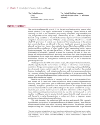
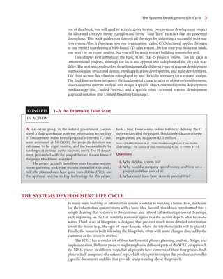
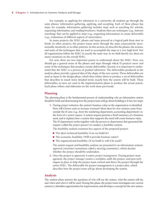
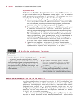
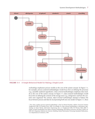
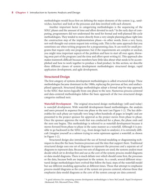
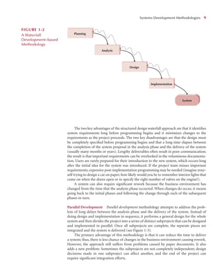
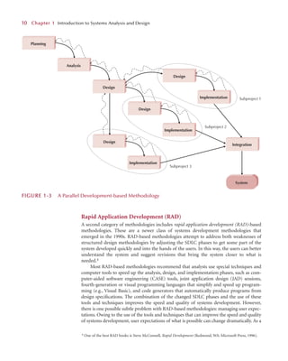
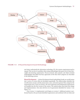
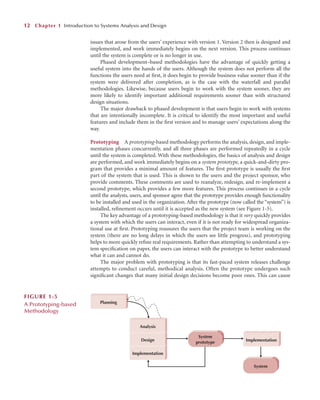
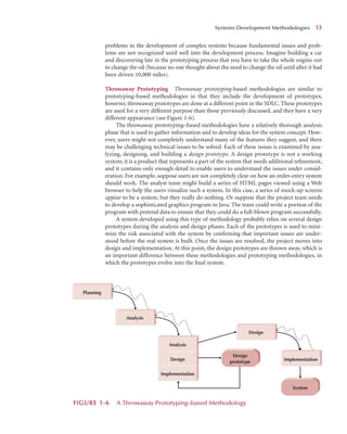
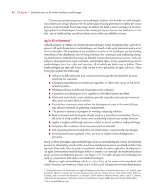
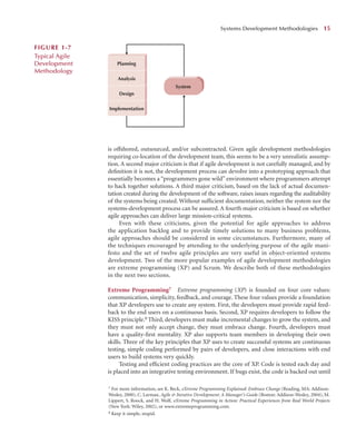
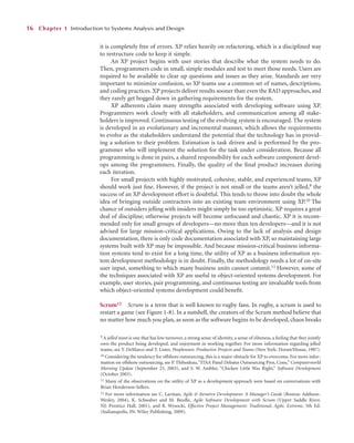
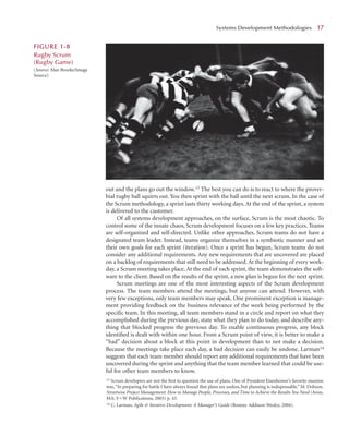
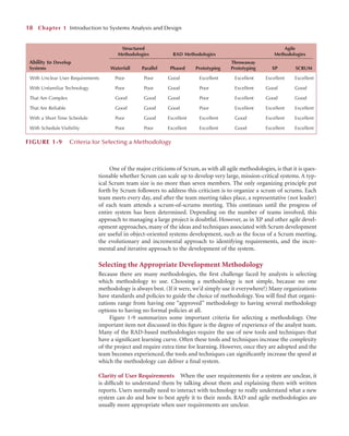
![In addition to these six general skill sets, analysts require many specific skills associated
with roles performed on a project. In the early days of systems development, most organi-
zations expected one person, the analyst, to have all the specific skills needed to conduct a
systems development project. Some small organizations still expect one person to perform
many roles, but because organizations and technology have become more complex, most
large organizations now build project teams containing several individuals with clearly
defined responsibilities. Different organizations divide the roles differently, but Figure 1-10
presents one commonly used set of project team roles. Most IS teams include many other
individuals, such as the programmers, who actually write the programs that make up the
system, and technical writers, who prepare the help screens and other documentation (e.g.,
users manuals and systems manuals).
Business Analyst
A business analyst focuses on the business issues surrounding the system. These issues include
identifying the business value that the system will create, developing ideas and suggestions for
how the business processes can be improved, and designing the new processes and policies in
conjunction with the systems analyst. This individual likely has business experience and some
type of professional training (e.g., the business analyst for accounting systems is likely a CPA
[in the United States] or a CA [in Canada]). He or she represents the interests of the project
sponsor and the ultimate users of the system. A business analyst assists in the planning and
design phases but is most active in the analysis phase.
Systems Analyst
A systems analyst focuses on the IS issues surrounding the system. This person develops
ideas and suggestions for how information technology can improve business processes,
designs the new business processes with help from the business analyst, designs the new
information system, and ensures that all IS standards are maintained. A systems analyst
Typical Systems Analyst Roles and Skills 21
Business analyst Analyzing the key business aspects of the system
Identifying how the system will provide business value
Designing the new business processes and policies
Systems analyst Identifying how technology can improve business processes
Designing the new business processes
Designing the information system
Ensuring that the system conforms to information systems standards
Infrastructure analyst Ensuring the system conforms to infrastructure standards
Identifying infrastructure changes needed to support the system
Change management analyst Developing and executing a change management plan
Developing and executing a user training plan
Project manager Managing the team of analysts, programmers, technical writers, and
other specialists
Developing and monitoring the project plan
Assigning resources
Serving as the primary point of contact for the project
Role Responsibilities
FIGURE 1-10
Project Team Roles](https://image.slidesharecdn.com/21857336-250528124011-bfb26cb2/85/Systems-Analysis-And-Design-Uml-Version-20-An-Objectoriented-Approach-Alan-Dennis-40-320.jpg)