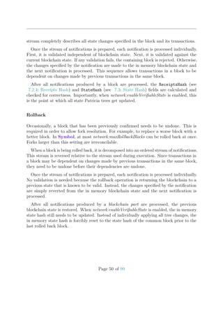
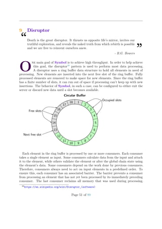
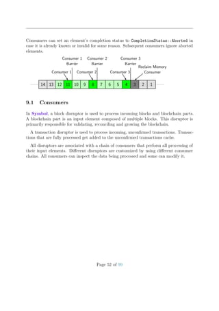
This document provides a technical overview of the Symbol blockchain protocol. It describes the key components of the Symbol system including transactions, blocks, accounts, addresses, cryptography, trees, networking, consensus and more. The goal in developing Symbol was to create a trustless, high-performance, layered blockchain architecture that improves upon the original NEM protocol.

![1 Introduction
“From the ashes a fire shall be woken,
A light from the shadows shall spring;
Renewed shall be blade that was broken,
The crownless again shall be king.
”- J.R.R. Tolkien
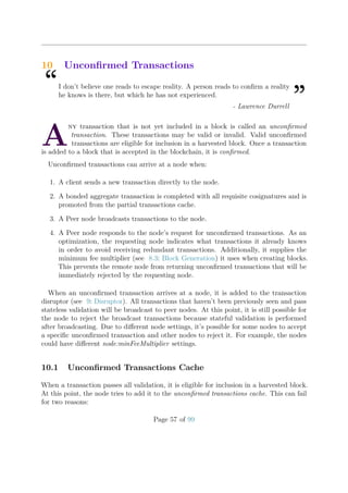
T
rustless, high-performance, layered-architecture, blockchain-based DLT protocol
- these are the first principles that influenced the development of Symbol. While
other DLT protocols were considered, including DAG and dBFT, blockchain
was quickly chosen as the protocol most true to the ideal of trustlessness. Any node can
download a complete copy of the chain and can independently verify it at all times. Nodes
with sufficient harvesting power can always create blocks and never need to rely on a
leader. These choices necessarily sacrifice some throughput relative to other protocols, but
they seem most consistent with the philosophical underpinnings of Bitcoin[Nak09].
As part of a focus on trustlessness, the following features were added relative to NEM:
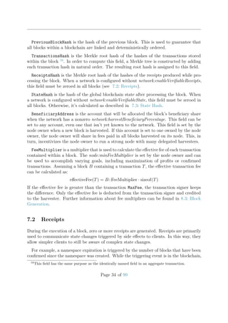
• Block headers can be synced without transaction data, while allowing verification of
chain integrity.
• Transaction Merkle trees allow cryptographic proofs of transaction containment (or
not) within blocks.
• Receipts increase the transparency of indirectly triggered state changes.
• State proofs allow trustless verification of specific state within the blockchain.
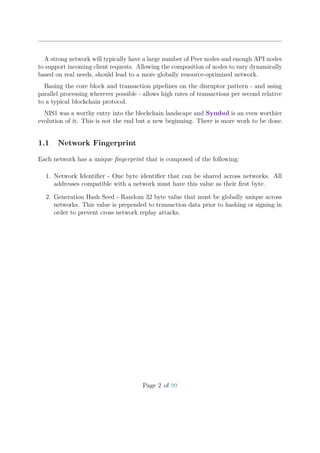
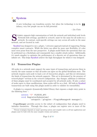
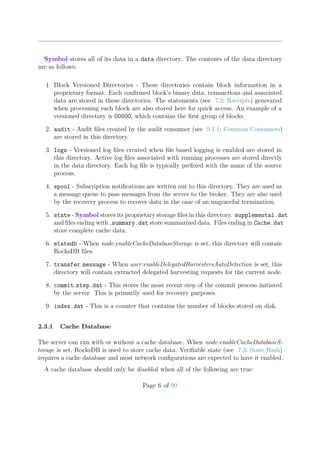
In Symbol, there is a single server executable that can be customized by loading
different plugins (for transaction support) and extensions (for functionality). There are
three primary configurations (per network), but further customized hybrid configurations
are possible by enabling or disabling specific extensions.
The three primary configurations are:
1. Peer: These nodes are the backbone of the network and create new blocks.
2. API: These nodes store data in a MongoDB database for easier querying and can be
used in combination with a NodeJS REST server.
3. Dual: These nodes perform the functions of both Peer and API nodes.
Page 1 of 99](https://image.slidesharecdn.com/symbolfromnemwhitepaper0-200723154303/85/Symbol-from-NEM-Whitepaper-0-9-6-3-8-320.jpg)

![3 Cryptography
“I understood the importance in principle of public key cryptography but it’s
all moved much faster than I expected. I did not expect it to be a mainstay of
advanced communications technology.
”- Whitfield Diffie
B
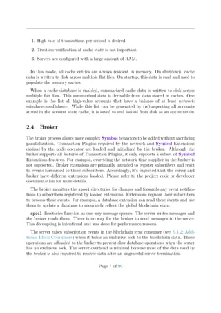
lockchain technology demands the use of some cryptographic concepts. Symbol
uses cryptography based on Elliptic Curve Cryptography (ECC). The choice of
the underlying curve is important in order to guarantee security and speed.
Symbol uses the Ed25519 digital signature algorithm. This algorithm uses the following
Twisted Edwards curve:
−x2
+ y2
= 1 −
121665
121666
x2
y2
over the finite field defined by the prime number 2255
−19. The base point for the correspond-
ing group G is called B. The group has q = 2252
+27742317777372353535851937790883648493
elements. It was developed by D. J. Bernstein et al. and is one of the safest and fastest
digital signature algorithms [Ber+11].
Importantly for Symbol purposes, the algorithm produces short 64-byte signatures and
supports fast signature verification. Neither key generation nor signing is used during
block processing, so the speed of these operations is unimportant.
3.1 Public/Private Key Pair
A private key is a random 256-bit integer k. To derive the public key A from it, the
following steps are taken:
H(k) = (h0, h1, . . . , h511) (1)
a = 2254
+
3≤i≤253
2i
hi (2)
A = aB (3)
Since A is a group element, it can be encoded into a 256-bit integer A, which serves as
the public key.
Page 9 of 99](https://image.slidesharecdn.com/symbolfromnemwhitepaper0-200723154303/85/Symbol-from-NEM-Whitepaper-0-9-6-3-16-320.jpg)
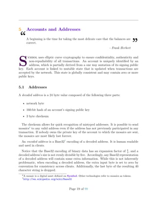
![3.2 Signing and Verification
Given a message M, private key k and its associated public key A, the following steps are
taken to create a signature:
H(k) = (h0, h1, . . . , h511) (4)
r = H(h256, . . . , h511, M) where the comma means concatenation (5)
R = rB (6)
S = (r + H(R, A, M)a) mod q (7)
Then (R, S) is the signature for the message M under the private key k. Note that only
signatures where S < q and S > 0 are considered as valid to prevent the problem of
signature malleability.
To verify the signature (R, S) for the given message M and public key A, the verifier
checks S < q and S > 0 and then calculates
˜R = SB − H(R, A, M)A
and verifies that
˜R = R (8)
If S was computed as shown in (7) then
SB = rB + (H(R, A, M)a)B = R + H(R, A, M)A
so (8) will hold.
3.2.1 Batch Verification
When lots of signatures have to be verified, a batch signature verification can speed up the
process by about 80%. Symbol uses the algorithm outlined in [Ber+11]. Given a batch of
(Mi, Ai, Ri, Si) where (Ri, Si) is the signature for the message Mi with public key Ai, let
Hi = H(Ri, Ai, Mi). Additionally, assume a corresponding number of uniform distributed
128-bit independent random integers zi are generated. Now consider the equation:
−
i
ziSi mod q B +
i
ziRi +
i
(ziHi mod q)Ai = 0 (9)
Setting Pi = 8Ri + 8HiAi − 8SiB, then if (9) holds, it implies
i
ziPi = 0 (10)
Page 10 of 99](https://image.slidesharecdn.com/symbolfromnemwhitepaper0-200723154303/85/Symbol-from-NEM-Whitepaper-0-9-6-3-17-320.jpg)
![All Pi are elements of a cyclic group (remember q is a prime). If some Pi is not zero, for
example P2, it means that for given integers z0, z1, z3, z4 . . ., there is exactly one choice
for z2 to satisfy (10). The chance for that is 2−128
. Therefore, if (9) holds, it is a near
certainty that Pi = 0 for all i. This implies that the signatures are valid.
If (9) does not hold, it means that there is at least one invalid signature. In that case,
Symbol falls back to single signature verification to identify the invalid signatures.
3.3 Verifiable Random Function (VRF)
A verifiable random function (VRF) uses a public/private key pair to generate pseudo-
random values. Only the owner of the private key can generate a value such that it cannot
be predetermined by an adversary. Anyone with the public key can verify whether or
not the value was generated by its associated private key. Symbol uses the ECVRF-
EDWARDS25519-SHA512-TAI defined in [Gol+20].
To generate a proof4
given a public key Y corresponding to a private key SK = xB and
an input seed alpha5
:
H = map to group element(alpha, Y )
γ = xH
k = generate nonce(H)
c = IetfHash(3, 2, H, γ, kB, kH)[0..15]
s = (k + cx) mod q
proof = (γ, c, s)
The proof produced by the function above can be verified with the following procedure:
H = map to group element(alpha, Y )
U = sB − cY
V = sH − cγ
verification hash = IetfHash(3, 2, H, γ, U, V )[0..15]
When the calculated verification hash matches the c part of the proof, the verification
of the random value is successful.
4
This is typically called proving, not to be confused with verifying, because the private key owner
needs to prove that it generated the random value with its private key.
5
The listings provided in this section do not define auxiliary functions. Full descriptions of these
functions can be found in [Gol+20].
Page 11 of 99](https://image.slidesharecdn.com/symbolfromnemwhitepaper0-200723154303/85/Symbol-from-NEM-Whitepaper-0-9-6-3-18-320.jpg)

![4 Trees
“All our wisdom is stored in the trees.
”- Santosh Kalwar
S
ymbol uses tree structures in order to support trustless light clients. Merkle trees
allow a client to cryptographically confirm the existence of data stored within
them. Patricia trees allow a client to cryptographically confirm the existence or
non-existence of data stored within them.
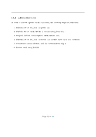
4.1 Merkle Tree
A Merkle tree[Mer88] is a tree of hashes that allows efficient existence proofs. Within
Symbol, all basic merkle trees are constrained to being balanced and binary. Each leaf
node contains a hash of some data. Each non-leaf node is constructed by hashing the
hashes stored in child nodes. In the Symbol implementation, when any (non-root) layer
contains an odd number of hashes, the last hash is doubled when calculating the parent
hash.
Merkle Hash = HRoot =
H(HABCD, HEE2 )
HABCD =
H(HAB, HCD)
HAB =
H(H(A), H(B))
H(A)
A
H(B)
B
HCD =
H(H(C), H(D))
H(C)
C
H(D)
D
HEE2 =
H(HEE, HEE)
HEE =
H(H(E), H(E))
H(E)
E
Figure 1: Four level Merkle tree composed of five data items
A benefit of using merkle trees is that the existence of a hash in a tree can be proven
with only log(N) hashes. This allows for existence proofs with relatively low bandwidth
requirements.
Page 13 of 99](https://image.slidesharecdn.com/symbolfromnemwhitepaper0-200723154303/85/Symbol-from-NEM-Whitepaper-0-9-6-3-20-320.jpg)
![Merkle Hash = HRoot =
H(HABCD, HEE2 )
HABCD =
H(HAB, HCD)
HAB =
H(H(A), H(B))
H(A)
A
H(B)
B
HCD =
H(H(C), H(D))
H(C)
C
H(D)
D
HEE2 =
H(HEE, HEE)
HEE =
H(H(E), H(E))
H(E)
E
Figure 2: Merkle proof required for proving existence of B in the tree
A merkle proof for existence requires a single hash from each level of the tree. In order
to prove the existence of B, a client must:
1. Calculate H(B).
2. Obtain HRoot; in Symbol, this is stored in the block header.
3. Request H(A), HCD, HEE2 .
4. Calculate HRoot = H(H(H(H(A), H(B)), HCD), HEE2 ).
5. Compare HRoot and HRoot ; if they match, H(B) must be stored in the tree.
4.2 Patricia Tree
A Patricia tree[Mor68] is a deterministically ordered tree. It is constructed from key value
pairs, and supports both existence and non-existence proofs requiring only log(N) hashes.
Non-existence proofs are possible because this tree is deterministically sorted by keys. The
application of the same data, in any order, will always result in the same tree.
When inserting a new key value pair into the tree, the key is decomposed into nibbles
and each nibble is logically its own node in the tree. All keys within a single tree are
required to have the same length, which allows slightly optimized algorithms.
Page 14 of 99](https://image.slidesharecdn.com/symbolfromnemwhitepaper0-200723154303/85/Symbol-from-NEM-Whitepaper-0-9-6-3-21-320.jpg)
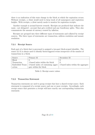
![For illustration, consider the following key value pairs in Table 2. Some examples will
use ASCII keys to more clearly elucidate concepts, while others will use hex keys to more
accurately depict Symbol implementations.
Figure 3 depicts a full Patricia tree where each letter is represented by a separate node.
Although this tree is logically correct, it is quite expansive and uses a lot of memory. A
typical key is a 32 byte hash value, which implies that storing a single value could require
up to 64 nodes. In order to work around this limitation, successive empty branch nodes
can be collapsed into either a branch node with at least two connections or a leaf node.
This leads to a different but more compact tree, as depicted in Figure 4.
key hex-key value
do** 646F0000 verb
dog* 646F6700 puppy
doge 646F6765 mascot
hors 686F7273 stallion
Table 2: Patricia tree example data
Root
D
O
*
* [verb]
G
* [puppy] E [mascot]
H
O
R
S [stallion]
Figure 3: Conceptual (expanded) Patricia tree composed of four data items
Page 15 of 99](https://image.slidesharecdn.com/symbolfromnemwhitepaper0-200723154303/85/Symbol-from-NEM-Whitepaper-0-9-6-3-22-320.jpg)
![Root
DO
** [verb] G
* [puppy] E [mascot]
HORS [stallion]
Figure 4: Conceptual (compact) patricia tree composed of four data items
4.3 Merkle Patricia Tree
A Merkle Patricia tree is a combination of Merkle and Patricia trees. The Symbol
implementation centers around two types of nodes: leaf nodes and branch nodes. Each
leaf node contains a hash of some data. Each branch node contains up to sixteen pointers
to child nodes.
Like in a basic Merkle tree, each Merkle Patricia tree has a root hash, but the hashes
stored in the Merkle Patricia tree are slightly more complex.
Every node in the tree has a tree node path. This path is composed of a sentinel nibble
followed by zero or more path nibbles. If the path represents a leaf node, 0x2 will be set
in the sentinel nibble. If the path is composed of an odd number of nibbles, 0x1 will be
set in the sentinel nibble and the second nibble will contain the first path nibble. If the
path is composed of an even number, the second nibble will be set to 0x0 and the second
byte will contain the first path nibble.
A leaf node is composed of the following two items:
1. TreeNodePath: Encoded tree node path (with leaf bit set).
2. ValueHash: Hash of the value associated with the key ending at the leaf.
The hash of a leaf node can be calculated by hashing its component parts:
H(Leaf ) = H(TreeNodePath, ValueHash)
.
A branch node is composed of the following items:
Page 16 of 99](https://image.slidesharecdn.com/symbolfromnemwhitepaper0-200723154303/85/Symbol-from-NEM-Whitepaper-0-9-6-3-23-320.jpg)
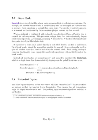
![odd path 0 0 bleaf 1 nibble1 nibble2..nibbleN[odd]
sentinel nibble
byte 1
even path 0 0 bleaf 0 0000 nibble1..nibbleN[even]
sentinel nibble
byte 1
Figure 5: Tree node path encoding
1. TreeNodePath: Encoded tree node path (with leaf bit unset).
2. LinkHash0, . . . , LinkHash15: Hashes of children where the index is the next nibble
part of the path. When no child is present at an index, a zero hash should be used
instead.
The hash of a branch node can be calculated by hashing its component parts:
H(Branch) = H(TreeNodePath, LinkHash0, . . . , LinkHash15)
.
Reconstructing the earlier example with hex keys yields a tree that illustrates a more
accurate view of how a Symbol tree is constructed. Notice that each branch node index
composes a single nibble of the path. This is depicted in Figure 6.
4.4 Merkle Patricia Tree Proofs
A Merkle proof for existence requires a single node from each level of the tree. In order to
prove the existence of {key = 646F6765, value = H(mascot)}, a client must:
1. Calculate H(mascot) (remember, all leaf values are hashes).
2. Request all nodes on the path 646F6765: Node6, Node646F , Node646F67.
3. Verify that Node646F67 :: Link[6] is equal to H(Leaf(mascot)).
Page 17 of 99](https://image.slidesharecdn.com/symbolfromnemwhitepaper0-200723154303/85/Symbol-from-NEM-Whitepaper-0-9-6-3-24-320.jpg)
![6
6F
000 [verb] 7
0 [puppy] 5 [mascot]
6F7273 [stallion]
4 8
0 6
0 6
Figure 6: Realistic Patricia tree with branch and leaf nodes and all optimizations. Path to
mascot [646F6765] is highlighted.
4. Calculate H(Node646F67) and verify that Node6467 :: Link[6] is equal to H(Node646F67).
5. Calculate H(Node6467) and verify that Node6 :: Link[4] is equal to H(Node6467).
6. Existence is proven if all calculated and actual hashes match.
A Merkle proof for non-existence requires a single node from each level of the tree. In
order to prove the non-existence of {key = 646F6764, value = H(mascot)}, a client must:
1. Calculate H(mascot) (remember, all leaf values are hashes).
2. Request all nodes on the path 646F6764: Node6, Node646F , Node646F67.
3. Verify that Node646F67 :: Link[5] is equal to H(Leaf(mascot)). Since Link[5] is unset,
this check will fail. If the value being searched for was in the tree, it must be linked
to this node because of the determinism of the tree.
Page 18 of 99](https://image.slidesharecdn.com/symbolfromnemwhitepaper0-200723154303/85/Symbol-from-NEM-Whitepaper-0-9-6-3-25-320.jpg)

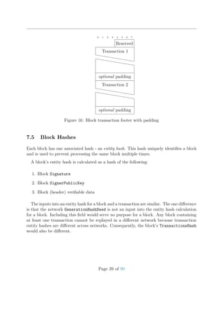
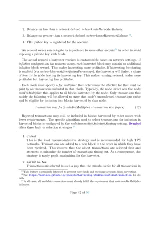
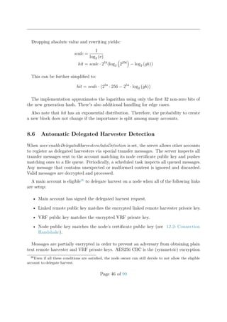

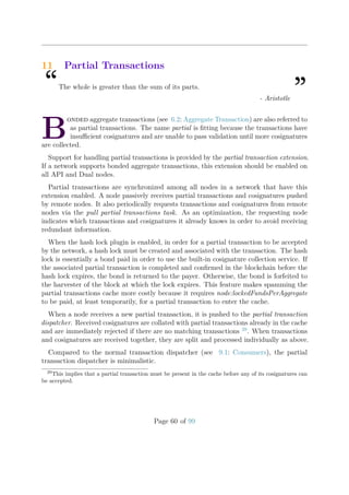
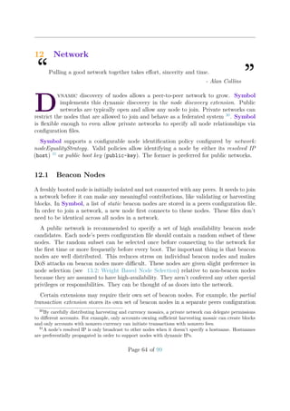
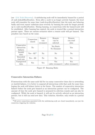
![2. If the new transaction is a bonded aggregate transaction, throttling is bypassed.
3. Else the Spam throttle is applied.
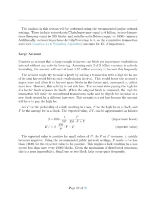
Let curSize be the current number of transactions in the cache and maxSize the config-
ured maximum size of the cache. Also let rel. importance of A be the relative importance
of A, i.e. a number between 0 and 1. If a new unconfirmed transaction T with signer A
arrives, then the fair share for account A is calculated:
maxBoostFee = transactionSpamThrottlingMaxBoostFee
maxFee = min(maxBoostFee, T::MaxFee)
eff. importance = (rel. importance of A) + 0.01 ·
maxFee
maxBoostFee
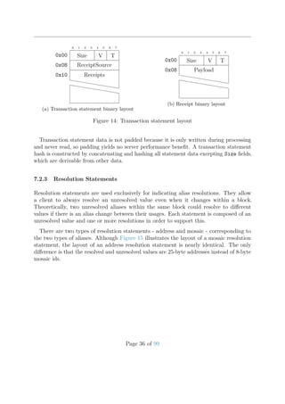
fair share = 100 · (eff. importance) · (maxSize − curSize) · exp −3
curSize
maxSize
If account A already has as many transactions in the cache as its fair share, then
the new transaction is rejected. Otherwise, it is accepted. The formula shows that an
increase in a transaction’s maximum fee increases the number of slots available in the
cache. Nonetheless, this mechanism for boosting the effective importance is limited by
node:transactionSpamThrottlingMaxBoostFee.
10 20 30 40 50 60 70 80 90 100
0
20
40
cache fill level [%]
fairshare
0.01%
0.005%
0.001%
Figure 20: Fair share for various effective importances with max cache size = 10000
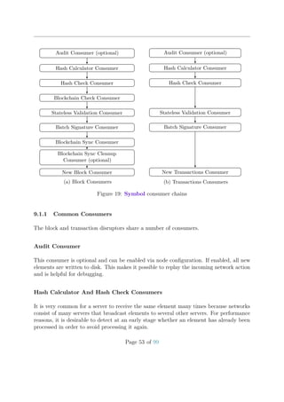
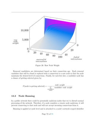
Figure 20 shows the fair share of slots relative to the fill level of the cache for various
effective importances. An attacker that tries to occupy many slots cannot gain much
by using many accounts because the importance of each account will be very low. The
attacker can increase maximum transaction fees but that will be more costly and expend
funds at a faster rate.
Page 59 of 99](https://image.slidesharecdn.com/symbolfromnemwhitepaper0-200723154303/85/Symbol-from-NEM-Whitepaper-0-9-6-3-66-320.jpg)
![14 Consensus
“You know what, sometimes it seems to me we’re living in a world that we
fabricate for ourselves. We decide what’s good and what isn’t, we draw maps
of meanings for ourselves... And then we spend our whole lives struggling with
what we have invented for ourselves. The problem is that each of us has our
own version of it, so people find it hard to understand each other.
”- Olga Tokarczuk
B
yzantine consensus is a key problem faced by all decentralized systems. Es-
sentially, the crux of the problem is finding a way to get independent actors
to cooperate without cheating. Bitcoin’s key innovation was a solution to this
problem that is based on Proof of Work (PoW). After each new block is accepted into
Bitcoin’s main chain, all miners begin a competition to find the next block. All miners
are incentivized to extend the main chain instead of forks because the chain with the
greatest cumulative hashing power is the reference chain. Miners calculate hashes as
quickly as possible until one produces a candidate block with a hash below the current
network difficulty target. A miner’s probability of mining a block is proportional to the
miner’s hash rate relative to the network’s total hash rate. This necessarily leads to a
computational arms race and uses a lot of electricity.
Proof of Stake (PoS)[KN12][BCN13] blockchains were introduced after Bitcoin. They
presented an alternative solution to the Byzantine consensus problem that did not require
significant power consumption. Fundamentally, these chains behaved similarly to Bitcoin
with one important difference. Instead of predicating the probability of creating a block
on a node’s relative hash rate, the probability is based on a node’s relative stake in the
network. Since richer accounts are able to produce more blocks than poorer accounts, this
scheme tends to allow the rich to get richer.
Symbol uses a modified version of PoS that attempts to award users preferentially
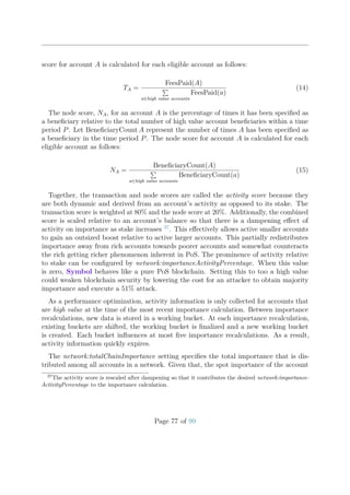
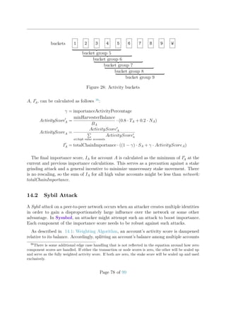
relative to hoarders. It strives to calculate a holistic score of an account’s importance
without sacrificing performance and scalability.
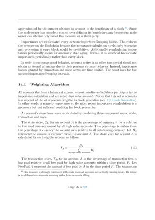
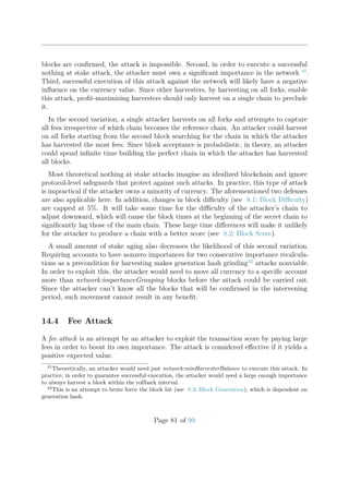
There are multiple factors that contribute to a healthy ecosystem. All else equal,
accounts with larger stakes making more transactions and running nodes have more skin in
the game and should be rewarded accordingly. Firstly, accounts with larger balances have
larger stakes in the network and have greater incentives to see the ecosystem as a whole
succeed. The amount of the currency an account owns is a measure of its stake. Secondly,
accounts should be encouraged to use the network by making transactions. Network usage
can be approximated by the total amount of transaction fees paid by an account. Thirdly,
accounts should be encouraged to run nodes to strengthen the network. This can be
Page 75 of 99](https://image.slidesharecdn.com/symbolfromnemwhitepaper0-200723154303/85/Symbol-from-NEM-Whitepaper-0-9-6-3-82-320.jpg)
![15 Time Synchronization
“Time and Tide wait for no man.
”- Geoffrey Chaucer
L
ike most other blockchains, Symbol relies on timestamps for the ordering of
transactions and blocks. Ideally, all nodes in the network should be synchronized
with respect to time. Even though most modern operating systems have time
synchronization integrated, nodes can still have local clocks that deviate from real time by
more than a minute. This causes those nodes to reject valid transactions or blocks, which
makes it impossible for them to synchronize with the network.
It is therefore needed to have a synchronization mechanism to ensure all nodes agree on
time. There are basically two ways to do this:
1. Use an existing protocol, such as Network Time Protocol (NTP)45
.
2. Use a custom protocol.
The advantage of using an existing protocol like NTP is that it is easy to implement
and the network time will always be near real time. This has the disadvantage that the
network relies on servers outside the network.
Using a custom protocol that only relies on the P2P network itself solves this problem,
but there is a trade off. It is impossible to guarantee that the network time is always
near real time. For an overview of different custom protocols see [Sci09]. Symbol uses a
custom protocol based on Chapter 3 of this thesis in order to be completely independent
from any outside entity. The protocol is implemented in the timesync extension.
15.1 Gathering Samples
Each node in the network manages an integer offset that is set to 0 at start. The local
system time in milliseconds adjusted by the offset (which can be negative) is the network
time (again in milliseconds) of the node.
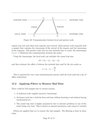
After the start up of a node is completed, the node (hereafter called local node) selects
partner nodes for performing a time synchronization round.
For each selected partner, the local node sends out a request asking the partner for
its current network time. The local node remembers the network timestamps when each
45
https://en.wikipedia.org/wiki/Network_Time_Protocol
Page 86 of 99](https://image.slidesharecdn.com/symbolfromnemwhitepaper0-200723154303/85/Symbol-from-NEM-Whitepaper-0-9-6-3-93-320.jpg)

![References
[BCN13] BCNext. Whitepaper:Nxt. Web document. 2013. url: https://nxtwiki.org/
wiki/Whitepaper:Nxt#Blocks.
[Ber+11] Daniel J. Bernstein et al. “High-Speed High-Security Signatures”. In: Crypto-
graphic Hardware and Embedded Systems - CHES 2011 - 13th International
Workshop, Nara, Japan, September 28 - October 1, 2011. Proceedings. 2011,
pp. 124–142. doi: 10.1007/978-3-642-23951-9_9. url: http://dx.doi.
org/10.1007/978-3-642-23951-9_9.
[Gol+20] Sharon Goldberg et al. Verifiable Random Functions (VRFs). Internet-Draft
draft-irtf-cfrg-vrf-07. Work in Progress. Internet Engineering Task Force, June
2020. 39 pp. url: https://datatracker.ietf.org/doc/html/draft-irtf-
cfrg-vrf-07.
[KN12] Sunny King and Scott Nadal. PPCoin: Peer-to-Peer Crypto-Currency with
Proof-of-Stake. Web document. Aug. 2012. url: https : / / decred . org /
research/king2012.pdf.
[Mer88] R. C. Merkle. “A Digital Signature Based on a Conventional Encryption
Function”. In: Advances in Cryptology — CRYPTO ’87. 1988, pp. 369–378.
[Mor68] Donald R. Morrison. “PATRICIA - Practical Algorithm to Retrieve Information
Coded in Alphanumeric”. In: Journal of the ACM, 15(4). 1968, pp. 514–534.
[Nak09] Satoshi Nakamoto. Bitcoin: A peer-to-peer electronic cash system. 2009. url:
http://www.bitcoin.org/bitcoin.pdf.
[Sci09] Sirio Scipioni. “Algorithms and Services for Peer-to-Peer Internal Clock Syn-
chronization”. PhD thesis. Universit‘a degli Studi di Roma „La Sapienza”,
2009.
Page 98 of 99](https://image.slidesharecdn.com/symbolfromnemwhitepaper0-200723154303/85/Symbol-from-NEM-Whitepaper-0-9-6-3-105-320.jpg)