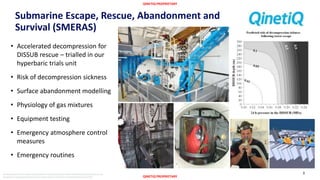
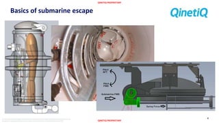
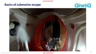
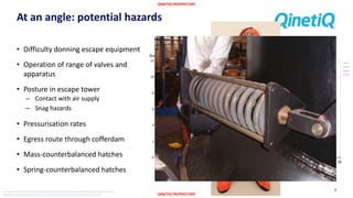
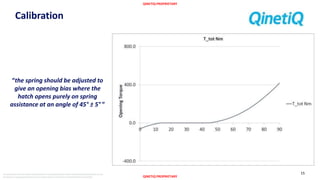
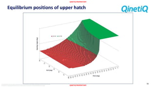
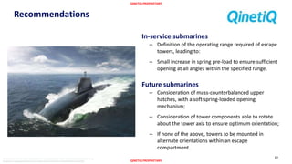
QINETIQ PROPRIETARY
QINETIQ PROPRIETARY
The document and informationcontained herein is proprietaryinformationof QinetiQ Limitedand shall not be
disclosed or reproduced without the prior authorisationof QinetiQ Limited.©QinetiQ Limited 2015
Submarine Escape at an Angle
Opening of and egress through an escape
tower upper hatch
1
Josh Peckham
Maritime Life Support
PACIFIC 2015 International
Maritime Conference
QINETIQ PROPRIETARY
QINETIQ PROPRIETARY
The document and informationcontained herein is proprietaryinformationof QinetiQ Limitedand shall not be
disclosed or reproduced without the prior authorisationof QinetiQ Limited.©QinetiQ Limited 2015
QinetiQ Maritime Life Support
‘protecting people in
extreme environments’
diving
engineering and physiology
forensic investigation
atmosphere control
monitoring and control
submarines and surface ships
SMERAS
engineering and physiology
2
QINETIQ PROPRIETARY
QINETIQ PROPRIETARY
The document and informationcontained herein is proprietaryinformationof QinetiQ Limitedand shall not be
disclosed or reproduced without the prior authorisationof QinetiQ Limited.©QinetiQ Limited 2015
Submarine Escape, Rescue, Abandonment and
Survival (SMERAS)
• Accelerated decompression for
DISSUB rescue – trialled in our
hyperbaric trials unit
• Risk of decompression sickness
• Surface abandonment modelling
• Physiology of gas mixtures
• Equipment testing
• Emergency atmosphere control
measures
• Emergency routines
3
QINETIQ PROPRIETARY
QINETIQ PROPRIETARY
The document and informationcontained herein is proprietaryinformationof QinetiQ Limitedand shall not be
disclosed or reproduced without the prior authorisationof QinetiQ Limited.©QinetiQ Limited 2015
Basics of submarine escape
4
QINETIQ PROPRIETARY
QINETIQ PROPRIETARY
The document and informationcontained herein is proprietaryinformationof QinetiQ Limitedand shall not be
disclosed or reproduced without the prior authorisationof QinetiQ Limited.©QinetiQ Limited 2015
Basics of submarine escape
5
QINETIQ PROPRIETARY
QINETIQ PROPRIETARY
The document and informationcontained herein is proprietaryinformationof QinetiQ Limitedand shall not be
disclosed or reproduced without the prior authorisationof QinetiQ Limited.©QinetiQ Limited 2015
HMS THETIS: 1939
6
• FWD compartments
flooded
• 35° bow-down
• 4 successful escapes
• 99 fatalities
QINETIQ PROPRIETARY
QINETIQ PROPRIETARY
The document and informationcontained herein is proprietaryinformationof QinetiQ Limitedand shall not be
disclosed or reproduced without the prior authorisationof QinetiQ Limited.©QinetiQ Limited 2015
At an angle: potential hazards
• Difficulty donning escape equipment
• Operation of range of valves and
apparatus
• Posture in escape tower
– Contact with air supply
– Snag hazards
• Pressurisation rates
• Egress route through cofferdam
• Mass-counterbalanced hatches
• Spring-counterbalanced hatches
7
QINETIQ PROPRIETARY
QINETIQ PROPRIETARY
The document and informationcontained herein is proprietaryinformationof QinetiQ Limitedand shall not be
disclosed or reproduced without the prior authorisationof QinetiQ Limited.©QinetiQ Limited 2015
Clearance required
8
• DefStan 00-250
– 605 mm width + 6 mm combat clothing
– 500 mm height + 13 mm combat clothing
• QinetiQ MLS study of escape suit
dimensions
– 620 mm shoulder breadth
– 450 mm hood depth
• QinetiQ anthropometry study
– 606 mm bi-deltoid breadth + 20 mm suit
– 401 mm abdomen/buttock depth + 20 mm
suit
QINETIQ PROPRIETARY
QINETIQ PROPRIETARY
The document and informationcontained herein is proprietaryinformationof QinetiQ Limitedand shall not be
disclosed or reproduced without the prior authorisationof QinetiQ Limited.©QinetiQ Limited 2015
LET clearance
9
𝛼 𝑐𝑟𝑖𝑡 = 62°
QINETIQ PROPRIETARY
QINETIQ PROPRIETARY
The document and informationcontained herein is proprietaryinformationof QinetiQ Limitedand shall not be
disclosed or reproduced without the prior authorisationof QinetiQ Limited.©QinetiQ Limited 2015
FET clearance
• Hatch brushes FWD edge of outer hull at
𝛼0 = 22°
• Distance 𝑟 from pivot to front edge is 746
mm
• Clearance required 𝑑 is 510 mm
• Clearance is distance between hatch and
DSRV seat – length of chord
10
𝑑 = 2𝑟 sin
𝛼 − 𝛼0
2
𝛼 𝑐𝑟𝑖𝑡 = 𝛼0 + 2 sin−1 𝑑 𝑐𝑟𝑖𝑡
2𝑟
𝛼 𝑐𝑟𝑖𝑡 = 62°
QINETIQ PROPRIETARY
QINETIQ PROPRIETARY
The document and informationcontained herein is proprietaryinformationof QinetiQ Limitedand shall not be
disclosed or reproduced without the prior authorisationof QinetiQ Limited.©QinetiQ Limited 2015
Pitch and roll
11
QINETIQ PROPRIETARY
QINETIQ PROPRIETARY
The document and informationcontained herein is proprietaryinformationof QinetiQ Limitedand shall not be
disclosed or reproduced without the prior authorisationof QinetiQ Limited.©QinetiQ Limited 2015
Torques acting on hatch
12
𝑐𝑜𝑠𝛽 = 𝑦ℎ𝑎𝑡𝑐ℎ ∙ 𝑦 = cos 𝜃 cos 𝜑 cos 𝛼 − sin 𝜃 sin 𝛼
Weight - 𝑀 − 𝑉ℎ𝑎𝑡𝑐ℎ 𝜌 𝑤 𝑔
𝜏 𝑔𝑟𝑎𝑣𝑖𝑡𝑦 = − 𝑀 − 𝑉ℎ𝑎𝑡𝑐ℎ 𝜌 𝑤 𝑔𝑐 cos 𝛽 𝜃, 𝜑, 𝛼 + 𝛾
Angle - cos 𝛽 𝜃, 𝜑, 𝛼 + 𝛾
𝑥 𝑘 = 𝑥 𝑘
0
− 𝐿 sin 𝛿 − sin 𝛿 − 𝛼
𝐹𝑘 = 𝑘𝑥 𝑘
Lever - 𝐿 cos 𝛿 − 𝛼
𝜏 𝑘 = 𝐿 cos 𝛿 − 𝛼 𝑘 𝑥 𝑘
0
− 𝐿 sin 𝛿 − sin 𝛿 − 𝛼
Partial VolumeFull Volume
𝜏 𝑎𝑖𝑟 = 𝑉𝑏𝑢𝑜𝑦 𝜌 𝑤 𝑔𝑟 cos 𝛽 𝜃, 𝜑, 𝛼 + 𝜀
𝐹𝑑 =
1
2
𝐶 𝑑 𝜌 𝑤 𝑣2
𝐴
𝜏 𝑑 = 𝑑𝜏 𝑑 = 𝑥 𝑑𝐹 = 𝑥
𝐶 𝑑 𝜌 𝑤 𝑣2
𝑥
2
𝑑𝐴
𝜏 𝑑 =
𝐶 𝑑 𝜌 𝑤 𝜔2
𝜋𝑅2
2
2
𝑅1
3
+
3
4
𝑅1 𝑅2
2
• Mass of hatch
• Buoyancy of air bubble
• Spring counterbalance
• Friction
– Dynamic fluid friction
– Dynamic hinge friction
– Static hinge friction
QINETIQ PROPRIETARY
QINETIQ PROPRIETARY
The document and informationcontained herein is proprietaryinformationof QinetiQ Limitedand shall not be
disclosed or reproduced without the prior authorisationof QinetiQ Limited.©QinetiQ Limited 2015
Implementation: MATLAB® Simscape™
13
QINETIQ PROPRIETARY
QINETIQ PROPRIETARY
The document and informationcontained herein is proprietaryinformationof QinetiQ Limitedand shall not be
disclosed or reproduced without the prior authorisationof QinetiQ Limited.©QinetiQ Limited 2015
Implementation: MS® Excel®
14
QINETIQ PROPRIETARY
QINETIQ PROPRIETARY
The document and informationcontained herein is proprietaryinformationof QinetiQ Limitedand shall not be
disclosed or reproduced without the prior authorisationof QinetiQ Limited.©QinetiQ Limited 2015
Calibration
“the spring should be adjusted to
give an opening bias where the
hatch opens purely on spring
assistance at an angle of 45° ± 5° ”
15
QINETIQ PROPRIETARY
QINETIQ PROPRIETARY
The document and informationcontained herein is proprietaryinformationof QinetiQ Limitedand shall not be
disclosed or reproduced without the prior authorisationof QinetiQ Limited.©QinetiQ Limited 2015
Equilibrium positions of upper hatch
16
QINETIQ PROPRIETARY
QINETIQ PROPRIETARY
The document and informationcontained herein is proprietaryinformationof QinetiQ Limitedand shall not be
disclosed or reproduced without the prior authorisationof QinetiQ Limited.©QinetiQ Limited 2015
Recommendations
In-service submarines
– Definition of the operating range required of escape
towers, leading to:
– Small increase in spring pre-load to ensure sufficient
opening at all angles within the specified range.
Future submarines
– Consideration of mass-counterbalanced upper
hatches, with a soft spring-loaded opening
mechanism;
– Consideration of tower components able to rotate
about the tower axis to ensure optimum orientation;
– If none of the above, towers to be mounted in
alternate orientations within an escape
compartment.
17
QINETIQ PROPRIETARY
QINETIQ PROPRIETARY
The document and informationcontained herein is proprietaryinformationof QinetiQ Limitedand shall not be
disclosed or reproduced without the prior authorisationof QinetiQ Limited.©QinetiQ Limited 2015
18
www.QinetiQ.com
FOLLOW US ON:
linkedin.com
/company/qinetiq_2
youtube.com
/user/QinetiQGroup
twitter.com
/QinetiQ
facebook.com
/qinetiqgroup

Submarine Escape at an Angle

  • 1.
    QINETIQ PROPRIETARY QINETIQ PROPRIETARY Thedocument and informationcontained herein is proprietaryinformationof QinetiQ Limitedand shall not be disclosed or reproduced without the prior authorisationof QinetiQ Limited.©QinetiQ Limited 2015 Submarine Escape at an Angle Opening of and egress through an escape tower upper hatch 1 Josh Peckham Maritime Life Support PACIFIC 2015 International Maritime Conference
  • 2.
    QINETIQ PROPRIETARY QINETIQ PROPRIETARY Thedocument and informationcontained herein is proprietaryinformationof QinetiQ Limitedand shall not be disclosed or reproduced without the prior authorisationof QinetiQ Limited.©QinetiQ Limited 2015 QinetiQ Maritime Life Support ‘protecting people in extreme environments’ diving engineering and physiology forensic investigation atmosphere control monitoring and control submarines and surface ships SMERAS engineering and physiology 2
  • 3.
    QINETIQ PROPRIETARY QINETIQ PROPRIETARY Thedocument and informationcontained herein is proprietaryinformationof QinetiQ Limitedand shall not be disclosed or reproduced without the prior authorisationof QinetiQ Limited.©QinetiQ Limited 2015 Submarine Escape, Rescue, Abandonment and Survival (SMERAS) • Accelerated decompression for DISSUB rescue – trialled in our hyperbaric trials unit • Risk of decompression sickness • Surface abandonment modelling • Physiology of gas mixtures • Equipment testing • Emergency atmosphere control measures • Emergency routines 3
  • 4.
    QINETIQ PROPRIETARY QINETIQ PROPRIETARY Thedocument and informationcontained herein is proprietaryinformationof QinetiQ Limitedand shall not be disclosed or reproduced without the prior authorisationof QinetiQ Limited.©QinetiQ Limited 2015 Basics of submarine escape 4
  • 5.
    QINETIQ PROPRIETARY QINETIQ PROPRIETARY Thedocument and informationcontained herein is proprietaryinformationof QinetiQ Limitedand shall not be disclosed or reproduced without the prior authorisationof QinetiQ Limited.©QinetiQ Limited 2015 Basics of submarine escape 5
  • 6.
    QINETIQ PROPRIETARY QINETIQ PROPRIETARY Thedocument and informationcontained herein is proprietaryinformationof QinetiQ Limitedand shall not be disclosed or reproduced without the prior authorisationof QinetiQ Limited.©QinetiQ Limited 2015 HMS THETIS: 1939 6 • FWD compartments flooded • 35° bow-down • 4 successful escapes • 99 fatalities
  • 7.
    QINETIQ PROPRIETARY QINETIQ PROPRIETARY Thedocument and informationcontained herein is proprietaryinformationof QinetiQ Limitedand shall not be disclosed or reproduced without the prior authorisationof QinetiQ Limited.©QinetiQ Limited 2015 At an angle: potential hazards • Difficulty donning escape equipment • Operation of range of valves and apparatus • Posture in escape tower – Contact with air supply – Snag hazards • Pressurisation rates • Egress route through cofferdam • Mass-counterbalanced hatches • Spring-counterbalanced hatches 7
  • 8.
    QINETIQ PROPRIETARY QINETIQ PROPRIETARY Thedocument and informationcontained herein is proprietaryinformationof QinetiQ Limitedand shall not be disclosed or reproduced without the prior authorisationof QinetiQ Limited.©QinetiQ Limited 2015 Clearance required 8 • DefStan 00-250 – 605 mm width + 6 mm combat clothing – 500 mm height + 13 mm combat clothing • QinetiQ MLS study of escape suit dimensions – 620 mm shoulder breadth – 450 mm hood depth • QinetiQ anthropometry study – 606 mm bi-deltoid breadth + 20 mm suit – 401 mm abdomen/buttock depth + 20 mm suit
  • 9.
    QINETIQ PROPRIETARY QINETIQ PROPRIETARY Thedocument and informationcontained herein is proprietaryinformationof QinetiQ Limitedand shall not be disclosed or reproduced without the prior authorisationof QinetiQ Limited.©QinetiQ Limited 2015 LET clearance 9 𝛼 𝑐𝑟𝑖𝑡 = 62°
  • 10.
    QINETIQ PROPRIETARY QINETIQ PROPRIETARY Thedocument and informationcontained herein is proprietaryinformationof QinetiQ Limitedand shall not be disclosed or reproduced without the prior authorisationof QinetiQ Limited.©QinetiQ Limited 2015 FET clearance • Hatch brushes FWD edge of outer hull at 𝛼0 = 22° • Distance 𝑟 from pivot to front edge is 746 mm • Clearance required 𝑑 is 510 mm • Clearance is distance between hatch and DSRV seat – length of chord 10 𝑑 = 2𝑟 sin 𝛼 − 𝛼0 2 𝛼 𝑐𝑟𝑖𝑡 = 𝛼0 + 2 sin−1 𝑑 𝑐𝑟𝑖𝑡 2𝑟 𝛼 𝑐𝑟𝑖𝑡 = 62°
  • 11.
    QINETIQ PROPRIETARY QINETIQ PROPRIETARY Thedocument and informationcontained herein is proprietaryinformationof QinetiQ Limitedand shall not be disclosed or reproduced without the prior authorisationof QinetiQ Limited.©QinetiQ Limited 2015 Pitch and roll 11
  • 12.
    QINETIQ PROPRIETARY QINETIQ PROPRIETARY Thedocument and informationcontained herein is proprietaryinformationof QinetiQ Limitedand shall not be disclosed or reproduced without the prior authorisationof QinetiQ Limited.©QinetiQ Limited 2015 Torques acting on hatch 12 𝑐𝑜𝑠𝛽 = 𝑦ℎ𝑎𝑡𝑐ℎ ∙ 𝑦 = cos 𝜃 cos 𝜑 cos 𝛼 − sin 𝜃 sin 𝛼 Weight - 𝑀 − 𝑉ℎ𝑎𝑡𝑐ℎ 𝜌 𝑤 𝑔 𝜏 𝑔𝑟𝑎𝑣𝑖𝑡𝑦 = − 𝑀 − 𝑉ℎ𝑎𝑡𝑐ℎ 𝜌 𝑤 𝑔𝑐 cos 𝛽 𝜃, 𝜑, 𝛼 + 𝛾 Angle - cos 𝛽 𝜃, 𝜑, 𝛼 + 𝛾 𝑥 𝑘 = 𝑥 𝑘 0 − 𝐿 sin 𝛿 − sin 𝛿 − 𝛼 𝐹𝑘 = 𝑘𝑥 𝑘 Lever - 𝐿 cos 𝛿 − 𝛼 𝜏 𝑘 = 𝐿 cos 𝛿 − 𝛼 𝑘 𝑥 𝑘 0 − 𝐿 sin 𝛿 − sin 𝛿 − 𝛼 Partial VolumeFull Volume 𝜏 𝑎𝑖𝑟 = 𝑉𝑏𝑢𝑜𝑦 𝜌 𝑤 𝑔𝑟 cos 𝛽 𝜃, 𝜑, 𝛼 + 𝜀 𝐹𝑑 = 1 2 𝐶 𝑑 𝜌 𝑤 𝑣2 𝐴 𝜏 𝑑 = 𝑑𝜏 𝑑 = 𝑥 𝑑𝐹 = 𝑥 𝐶 𝑑 𝜌 𝑤 𝑣2 𝑥 2 𝑑𝐴 𝜏 𝑑 = 𝐶 𝑑 𝜌 𝑤 𝜔2 𝜋𝑅2 2 2 𝑅1 3 + 3 4 𝑅1 𝑅2 2 • Mass of hatch • Buoyancy of air bubble • Spring counterbalance • Friction – Dynamic fluid friction – Dynamic hinge friction – Static hinge friction
  • 13.
    QINETIQ PROPRIETARY QINETIQ PROPRIETARY Thedocument and informationcontained herein is proprietaryinformationof QinetiQ Limitedand shall not be disclosed or reproduced without the prior authorisationof QinetiQ Limited.©QinetiQ Limited 2015 Implementation: MATLAB® Simscape™ 13
  • 14.
    QINETIQ PROPRIETARY QINETIQ PROPRIETARY Thedocument and informationcontained herein is proprietaryinformationof QinetiQ Limitedand shall not be disclosed or reproduced without the prior authorisationof QinetiQ Limited.©QinetiQ Limited 2015 Implementation: MS® Excel® 14
  • 15.
    QINETIQ PROPRIETARY QINETIQ PROPRIETARY Thedocument and informationcontained herein is proprietaryinformationof QinetiQ Limitedand shall not be disclosed or reproduced without the prior authorisationof QinetiQ Limited.©QinetiQ Limited 2015 Calibration “the spring should be adjusted to give an opening bias where the hatch opens purely on spring assistance at an angle of 45° ± 5° ” 15
  • 16.
    QINETIQ PROPRIETARY QINETIQ PROPRIETARY Thedocument and informationcontained herein is proprietaryinformationof QinetiQ Limitedand shall not be disclosed or reproduced without the prior authorisationof QinetiQ Limited.©QinetiQ Limited 2015 Equilibrium positions of upper hatch 16
  • 17.
    QINETIQ PROPRIETARY QINETIQ PROPRIETARY Thedocument and informationcontained herein is proprietaryinformationof QinetiQ Limitedand shall not be disclosed or reproduced without the prior authorisationof QinetiQ Limited.©QinetiQ Limited 2015 Recommendations In-service submarines – Definition of the operating range required of escape towers, leading to: – Small increase in spring pre-load to ensure sufficient opening at all angles within the specified range. Future submarines – Consideration of mass-counterbalanced upper hatches, with a soft spring-loaded opening mechanism; – Consideration of tower components able to rotate about the tower axis to ensure optimum orientation; – If none of the above, towers to be mounted in alternate orientations within an escape compartment. 17
  • 18.
    QINETIQ PROPRIETARY QINETIQ PROPRIETARY Thedocument and informationcontained herein is proprietaryinformationof QinetiQ Limitedand shall not be disclosed or reproduced without the prior authorisationof QinetiQ Limited.©QinetiQ Limited 2015 18
  • 19.

Editor's Notes

  • #2 Good (morning/afternoon) everybody. Thank you for coming to my presentation on Submarine Escape at an Angle. My name is Josh Peckham, and I work for QinetiQ UK in their Maritime Life Support team.
  • #3 QinetiQ is a former UK MOD evaluation and research agency, which was privatised in 2001. It advises the MOD in science, technology and engineering matters across the entire defence spectrum. My team, Maritime Life Support, works in three main areas. Our diving group (words from Mike). Our atmosphere control group (words from Steve). The group that I work in is Submarine Escape, Rescue Abandonment and Survival, dealing in both engineering and physiological aspects of the field.
  • #4 We have a wide range of capabilities. We conduct hyperbaric trials, looking at the effects of raised pressure on the human body in our hyperbaric trials unit. We use historical trials data to conduct modelling of decompression sickness. A recent piece of work has been predicting the likelihood of various types of decompression sickness according to different dive profiles, and my colleague is currently working on extending that to the probability of survival on the surface. We have modelled the abandonment routines of a submarine crew on the surface, looking at what factors increase or decrease the time taken. We frequently conduct physiological trials of various types. A recent trial investigated the effect of switching from a raised CO2 mixture to normal air to investigate reports of light-headedness, in particular when performing the Valsalva manoeuvre to equalise pressure. The motivation behind this will become clearer later. We test all in-service and potential RN SMERAS equipment; in the picture here you see an escape suit, the Beaufort Mk10, in our submarine escape simulator. This simulator is arranged inside the hyperbaric trials unit in the top picture and routinely simulates escape profiles of up to 200m, although its capabilities are much greater. We, along with the submarine atmosphere control team, test and benchmark the emergency atmosphere control equipment; carbon dioxide absorbent curtains and oxygen generation candles. We then model escape and survival scenarios in sunken submarines so that we can provide advice on how bet to use these resources. We use the same software set to predict the best practice for the crew in any disaster scenario, whether it be the decision to wait for rescue or attempt escape, when to deploy atmosphere control equipment or which method of escape to use. This advice is input into the Guardbook, the disaster handbook carried on all RN submarines.
  • #5 Submarine escape, as practiced by the RN, is a fairly straightforward concept. An escaper, dressed in an escape suit, climbs into a 1-man or 2-man airlock, or “tower”. Pictured is the 1-man Forward Escape Tower from an Astute-class submarine. The lower hatch is then sealed. A flood valve is opened, and as the tower floods with seawater the pressure of the air inside increases. The escaper throughout is plugged into an air supply which flushes the suit, and integrated hood, with air for both breathing and buoyancy. This allows the escaper to breath naturally, without a mouthpiece. In this picture you can see the tower from below. As you can see, it’s a bit claustrophobic! The upper hatch is mounted on a spring counterbalance system. When the pressure equalises, the spring acts on this lever arm and opens the hatch. This fibreglass plate is the flush with the outer hull; the escaper leaves the tower and floats to the surface, where they deploy an integrated liferaft. The tower meanwhile is emptied and prepared for the next escaper.
  • #6 We can watch a short video of the last bit of an escape. This was recorded during an EscapEx in Scotland by a GoPro. You can see the escaper breathing normally. Watch for him carrying out the Valsalva manoeuvre, demonstrating the pressure increase. Watch for the water coming up from the bottom then, at equalisation, the hatch cracking open and the remaining water pouring in. Then, as the turbulence clears, watch for him floating out. That was at 30 m. We recommend that, given the right setup, a person can survive escape out to a depth of up to 200 m! Of course, this EscapEx, and all platform trials, and most equipment design, is based on an upright submarine. But that is not always the case.
  • #7 On 1 June 1939, just before the outbreak of WW2, HMS Thetis was in Liverpool Bay undergoing diving trials. She was carrying over 170 % of her normal complement, including observers naval and civilian. “Teething issues” with the layout and procedures submarine resulted in No 5 torpedo tube’s bow cap being left open. Not a problem, until another confusion resulted in the inner door being opened. Water flooded in and the bow sank to the seabed. The stern, full of air, remained buoyant. The submarine was located without a problem, partly because the stern was still on the surface. On location, the crew attempted an escape. On the 5th escape, the escaper drowned due to a problem with the upper hatch. The tower was now blocked; no further escapes were possible, and the 98 other men on board died of carbon dioxide poisoning. Torpedo problems account for a large number of submarine sinkings; either flooding or explosions. These typically affect the forward compartments, and repeats of the Thetis scenario are highly conceivable. Seabed topology is another potential cause; when HMS Affray was located in 1951, she was found to be rolled at an angle of 50 degrees and HMS Vandal (1943) is at 35 degrees roll.
  • #8 When considering escape at an angle of either pitch or roll, there are a lot of potential hazards to consider. Between a scoping study in 2009 and a wide-ranging report earlier this year, QinetiQ has identified the following as the most likely factors to impede escape. The SEIE best imagined as a drysuit plus hood, and anybody who has put one of these on before will realise that it can be an awkward job. This may be more challenging on an uneven platform. It has been assessed though, that there are enough places where an escaper can find the support required that it’s not a serious risk. Some of the valves and other apparatus that are operated as part of the escape routine don’t have great support around them. One example is, in some older tower types the lower hatch has to be physically removed and replaced each time, and it’s heavy. We recommended improved deck layout in future submarines, and recommended that crews on current boats find some way of harnessing operators where required. A more significant issue is the posture in the larger 2-man escape towers. These are cavernous in comparison, and escapers have to both maintain posture to get through the upper hatch correctly and, crucially, maintain contact with the air supply to prevent drowning. Some likely ergonomic issues have been identified, and remedies suggested. Vented escape uses a vent pipe to maintain low pressure until the water level reaches it, where it closes automatically and pressurisation is over a shorter timespan. The height of the pipe is critical to the pressurisation rate; if the tower is tilted one way or another, the remaining air volume will vary and in some circumstances barotrauma might occur due to rapid pressurisation. The egress route needs to be assessed to identify potential snag or entrapment hazards, in conjunction with the operation of the hatches. Mass-counterbalanced hatches operate effectively at all angles, being independent of pitch and roll; however, currently these only feature as the lower hatch of one tower type. Most hatches are spring-counterbalanced, which may operate variably depending on angle of pitch or roll. This is the main topic that I’m presenting in this paper.
  • #9 To evaluate the risk, we have to know the clearance that we need. A few sources were considered: A couple of years ago we answered an urgent operational query from MOD as to the dimensions of the escape suit. We determined that it was, when inflated, 620 mm by 450 mm maximum. A 2007 anthropometric study by QinetiQ on UK service personnel determined that, for male sailors, the 99th percentile dimensions are 606 mm by 401 mm, to which 20 mm should be added to account for the suit as recommended in the query above. Finally, the relevant defence standard concerning crawl-spaces recommends 605 mm by 500 mm with some addition for combat clothing and equipment. The largest among these were chosen as the required clearance.
  • #10 How does this clearance map across to each escape tower type? Using a CAD model of the 2-man tower cofferdam, we determined that an opening angle of… 62 degrees would give the required depth, and a simple view from above shows that the breadth clearance is not compromised beyond the normal hatch diameter.
  • #11 In the absence of an equally good CAD model of the single-man towers, which are similar in their upper hatch, we used drawings and a datum that the hatch only just clears the front edge of the outer hull at an angle of 22 degrees. We took a distance r from the drawings and used the equation for the length of a chord. Rearranging this for the critical angle… We find, coincidentally, the same angle as for the 2-man tower. I’m skimming over a lot on the maths here – you can find full details in the paper accompanying this presentation.
  • #12 Now is a good time to clear up what we mean by pitch and roll. We used the definitions that a pilot would see on an artificial horizon; pitch it up about its “abeam” axis, then roll it about its “ahead” axis, then open the hatch about its “abeam” axis. The order that you define these in does matter in terms of the maths. A small animation here will demonstrate what I mean. As the submarine sinks, it comes into contact with a sloped seabed. It pitches up as it comes to rest. Once at rest, it rolls to Starboard. After a brief pause, we notice the hatch opening about a hinge astern. I’m not going to get bogged down into great detail regarding the equations used, just the principles. If you are desperate to know, then the associated paper illustrates it in more detail.
  • #13 We identify a range of torques acting to open or close the hatch. Its own weight; the force of the spring; the buoyancy of the remaining air; and the friction and drag in the system. First, you have the weight of the hatch itself. This is significant; in air, it weighs a couple of hundred kilos. We take the centre of mass in polar coordinates from the hinge, c and gamma. We not that gamma lines up with opening angle alpha; this is helpful. The weight of the hatch in water is its mass, minus the mass of water displaced, times gravity. The angle that the hatch makes with the vertical is beta; this is a function of the pitch, theta; the roll, phi; and opening angle, alpha. Again, see the paper. So, the force multiplied by the distance multiplied by the cosine of the angle between the force direction and the useful direction gives the torque. The buoyancy of the air bubble was determined in a similar way; the centre of the air bubble and it’s buoyancy (or negative weight) was determined and these, along with the angle between the force direction (upwards) and the useful direction (perpendicular to the hatch) gives the torque. We tried a few different assumptions of bubble form; initially that the air bubble is that volume above the uppermost bit of the rim. This was calculated by CAD. We compared this to the opening profile seen in video footage from SETT, but it didn’t give good results and we attempted a more complex solution. Later models assumed that the fairing plate fitted to the hatch retained air better than expected and we assumed that the whole volume of the hatch was filled with air. This allowed us to reproduce the opening characteristics seen from video footage. The spring counterbalance torque was noted to be acting on a lever of length L, initially angled aft by an angle delta. The initial spring compression was xk0. Thus, the relationship between spring extension and opening angle was determined. Hooke’s law says that the force is proportional to the compression or extension. This force is applied horizontally, and the distance of the application point is the length of the lever arm multiplied by the cosine of its angle forward or aft. If we combine these all together, the torque is given here… Finally, friction. Although this will not affect the final equilibrium position of the hatch, it will damp any oscillation about this point. There are a range of sources, but the hinge frictions will vary based on level of maintenance and is estimated to be lower than fluid drag. Fluid drag over the domed hatch can be calculated using a standard drag equation, albeit modified to account for the rotational motion. There are some fairly large assumptions made but, to be honest, whether this is correct or not is not the issue at hand; it was more that we needed an order-of-magnitude damping parameter for one of the model implementations, which this offers.
  • #14 We initially implemented the model in Simscape, a 1D dynamic modelling environment by The Mathworks. You can see its construction in this image; starting from a rotational inertia block, we connect a rotational hard stop and an ideal torque source. A sensor reads the angular position, feeding it into the signal processing block where the equations are carried out. The output torque is fed into the ideal torque source. It outputs to the Matlab workspace. We then animated it for your pleasure… But, as scientists and engineers, what we really want to see is energy curves. The Simscape output is great, but it only gives a single data point each time – the eventual angle of opening. The oscillations, the plots, are otherwise uninteresting.
  • #15 The simplest way for us to look at the equilibrium angles in more detail is in Excel. You can see the tables, all calculated from the parameters on the right. This table is interrogated to find the equilibrium positions. Unfortunately the results, and therefore parameters, are classified but this is showing the output from a fictional tower. We plotted the torques and potential energies as a function of opening angle, allowing us to better understand the interactions of the various forces, then generated a surface plot of the danger areas. You can see on here this region, indicating no problem (90 degrees). You can see the region where there is an equilibrium; brown is greater than 62 degrees open, and grey is less than, indicating a potential issue.
  • #16 As in the actual towers, the model requires some calibration. An instruction in the Equipment and Systems handbook tells the crew how to adjust the spring; when surfaced, i.e. without buoyancy, the hatch should be pushed up to 45 degrees, at which point the spring should take over, overcoming friction, and it will open fully. We adjusted the spring compression to reflect this; you can see the results in the graph. Clearly we neglected static friction earlier, and this explains the slight offset from zero that you are seeing. These characteristics were borne out on a recent boat visit. Throughout this process, we were comparing the output of the model with that observed through the SETT video footage and with that observed first-hand when surfaced. This allowed limited validation of the model’s spring, mass and buoyancy formulations. Further validation of the model may be provided by a 1/3 scale model to be tested in one of our facilities in the UK.
  • #17 Again, using our qualitative example, you can see that there is a region where the hatch is not predicted to open beyond 62 degrees. To remind you, this was the angle which, for both towers, would compromise the egress route for the 99th percentile. The brown region is where the hatch is not predicted to open fully, but the clearance should be sufficient. The large grey area indicates full opening. Pitch forward, that is where the hinge is uppermost, is left on the x-axis. This is predicted to compromise the hatch. Roll, on the y-axis, has not got much effect until large angles, where it slightly narrows the compromised region.
  • #18 So, as a result of these predictions, what are our recommendations? As regards in-service submarines, the towers “are what they are” to be clichéd about it. There are things that we can do though. First we need to determine the maximum angle at which they are expected to operate. We then, using the model along with platform testing, increase the pre-load on the counterbalance springs. This will have drawbacks however; the tower will be harder to close both when surfaced and during escape, and may tend to open more violently which may damage either the mechanism or the operator. So, what can we do in future to improve the operation? Our recommendations were as follows: the preferred solution is to counterbalance mass with mass, thereby removing this angular dependence. The opening profile could then be achieved with a less stiff spring mechanism which could even be disengaged when alongside. A less ideal and, frankly, more fantastical solution would be to feature towers where the mechanism could be rotated about the tower to ensure optimum opening under any circumstance. The main reason that this is included is that it was recommended alongside movable internal tower components, such as ladders and air supplies, for ergonomic concerns. If fixed spring-counterbalanced upper hatches are maintained similar to the current generation, then the least that should be done is to build redundancy into the system by mounting pairs of towers in alternate orientations, ensuring that at least one will operate effectively.