SlideShare a Scribd company logo
1 of 5
Download to read offline
1
STUDY ON ESTIMATION OF RE-ENTRY TIME AFTER BLASTING IN UNDERGROUND MINING
PT CIBALIUNG SUMBERDAYA, INDONESIA
Sandro Hanaehan SIRAIT1
, Nuhindro Priagung WIDODO1
, Mikha SIMANJUNTAK2
1
Department of Mining Engineering, Faculty of Mining and Petroleum Engineering,
Institut Teknologi Bandung, Indonesia
2
PT Cibaliung Sumberdaya, Indonesia
Abstract
CO gas is one of the few gases that are produced by blasting that is poisonous that must be removed before workers
start the next job. The time required to remove the blasting gas is called re-entry time. The study was conducted at
PT Cibaliung Sumberdaya (PT CSD) at Cibitung area and Cikoneng area. CO gas were measured using Riken Keiki
Gas Detector GX-2003 which has limit of 500 ppm, 1 ppm precision, and data recording capacity up to 10 hours for
10-second intervals. The measured data showed the ratio between the amount of carbon monoxide produced (l) by
the amount of explosives used (kg) had variation from 2.7 l/kg until 71 l/kg. The measurement curves are then
approached using matching curve so that E or effective diffusion coefficient at each location can be obtained. E with
L/d or hydraulic diameter ratio of the distance has relationship in the equation E=0.1595 (L/d) +5. E that is
produced by that equation are later used to estimate the time CO gas required to reach 25 ppm before the gas exit to
atmosphere through the main fan.
I. INTRODUCTION
This research is intended to study the spread of CO
gas produced by blasting so that this research
methodology can be used as consideration of re-entry
time estimation. The time required to remove the
blasting gas is called re-entry time.
This research was conducted in underground gold
mine PT Cibaliung Sumberdaya (PT CSD). PT CSD
is an underground gold mine in Indonesia using cut
and fill mining method. PT CSD has two mining
areas: Cikoneng area and Cibitung area that each has
132 kW main fan which draws fresh air into the mine
area through the portal.
Government regulation in KEPMEN 555 states limit
the levels of CO in an average time of 8 hours is 50
ppm. This value is a consideration for re-entry time or
the time needed to reach the levels of gas that does
not endanger workers.
To be able to estimate the re-entry time, authors used
matching curve method based on advection diffusion
equation. This study is the beginning of a research
study on the re-entry time in underground mines in
Indonesia. The results are site-specific for PT CSD
underground mine on the current state of research.
Along with the development of mines results the
existing ventilation data should be updated.
II. METHODOLOGY
In this study, CO gas are measured by gas detector
Riken Keiki GX-2003 which has an accuracy of 1
ppm, 500 ppm limit measure, and time interval 10
seconds.
To be able to measure the displacement of CO gas
generated during blasting, the gas detector is placed
and turned on before blasting takes place, ie
when charging or filling activities explosives. After
30 minutes after blasting or when the smoke
clearing is completed or when smoke was not seen
anymore authors inspect these locations
Gas detector placed in a safe location
from flyrock and also from water seeping in the walls
of the tunnel. Gas detector hung
on wiremesh or longstrap to be stuck strongly and not
easily fall as in Figure 1.
Figure 1 Placement of the gas detector
Data that has been stored by the gas detector and then
transferred to computer using an infrared
device using software GX-2003 datalogger. The data
is then transferred to Microsoft Excel sheet.
The equation state of concentration solutions for
advection-diffusion phenomena in one-dimensional
uniform flow is expressed as follows:
√
(
̅
)
Where,
C (x, t) = concentration at position x and time t
V = total substance in its original state (x = 0, t = 0)
t = time after the gas produced (s)
2
A = cross-sectional area of the flow (m2
)
x = distance from the point of gas produced (m)
ū = average velocity (m/s)
E= effective diffusion coefficient
The flowchart of this research is shown in Figure 2.
Figure 2 Flowchart of this research
III. DATA ANALYSIS
3.1 Profile of PT CSD Ventilation Systems
Measurement of the quantity and distribution of air in
the ventilation system of PT CSD are presented
in Table 1 and Figure 3.
Table 1 Distribution of the air quantity PT CSD
No Description
Air flow
(m3
/s)
Percentage
1 Intake air
Portal Cikoneng 169.3 100%
2 Exhaust air
a. Main Fan Cikoneng 86.3 50.97%
b. Main Fan Cibitung 83 49.76%
A) B)
Figure 3 Percentage air flow distribution of PT CSD;
(A) Air enters from Portal Cikoneng; (B) air exit
through Cikoneng and Cibitung Shaft
KEPMEN 555 regulates minimum air quantity based
on the capacity of the machine and the number of
employees that each work site underground mine
requires 0.03 m3
/s for each employee and for each
horse power of the diesel engine takes 0.05
m3
/s. Calculation of the minimum amount of air based
activities are presented in Table 2. HP stated amount
of horse power diesel engines and n states the number
of workers. CKN means Cikoneng mining area. CBT
means Cibitung mining area. Dec means decline area.
Table 2 The amount of air flow required and supplied
No Location
Diesel
Machine
Type
HP n
Air
Required
(m3
/s)
Air
Supplied
(m3
/s)
1 CKN 1135
LHD
Caterpillar
R1300
182 1 9.13 10.96
2 CKN 1065
LHD Atlas
Copco
Wagner
82 1 4.13 4.56
3 CKN 1120
Agi Truck
Terex
152 1 7.63 8.34
4 CBT 1061
Shotcreter
SIKA
74 2 3.77 2.25
5 CBT 1101
Backhoe
Loader
Caterpilar
87 1 4.38 3.45
6 CBT Dec
Jumbo Drill
Terex
MK35HE
154 2 7.77 6.43
3.2 CO Gas Measurement Result
Gas detector placed at a specific location in
accordance with the location of the
desired heading distance. Variation in the distance to
the blasting face is made of at least 20
meters. Heading blasting in the area are Cikoneng and
Cibitung area, as shown in Figure 4. Main ventilation
scheme are shown in Figure 5.
Measurements on the same heading with different
distance variation performed at different blasting
activities. Example of a measurement scheme blasting
locations with distance variation is expressed
in Figure 6.
182.
1
100
%
Intake Air
(m3/s)
Portal
Cikoneng
86.3
51%83
49%
Exhaust Air (m3/s)
Main Fan
Cibitung
Main Fan
Cikoneng
3
Figure 4 CO Gas Measurement Scheme
CO gas data were measured and plotted as a graph of
concentration versus time. The chart shows
Gaussian curve as shown in the example (1101
Cibitung area) in Figure 7. The gas detector has limit
to measure CO that is 500 ppm, so that the data above
limit can’t be detected. Authors predict that value
using matching curve as we can see in figure below in
[1101 CBT-1] curve line.
Figure 7 Measurement results graphs
From the available data, the amount of CO gas
produced from any blasting can be obtained. The
amount of CO gas produced to the amount of
explosives are plotted in the graph is expressed
in Figure 8.
Figure 8 Number of explosives by the amount of CO
gas
Figure 5 PT CSD underground mine scheme
0
100
200
300
400
500
600
700
0 5 10 15 20
CO(ppm)
Time (minute)
50 meter 115 meter 165 meter
0
500
1000
1500
2000
2500
3000
3500
4000
0 20 40 60 80 100
CO(l)
Explosives (kg)
[1101 CBT-1]
CO Volume= 1,300,000 cc
ū=0.37 m/s; L/d= 11.2
E=7 m2
/s
[1101 CBT-2]
CO Volume= 180,000 cc
ū=0.39 m/s; L/d= 25.7
E=10 m2
/s
[1101 CBT-3]
CO Volume= 764,000 cc
ū=0.55 m/s; L/d= 36.8
E=15 m2
/s
4
Figure 6 PT CSD main ventilation scheme
The measured data showed the ratio between the
amount of carbon monoxide produced (l) by the
amount of explosives used (kg) had variation from 2.7
l/kg until 71 l/kg with the average ratio is 18.7 l/kg
Because of that the amount of CO gas can not be
predicted directly using data on the number of
explosives. Further study is needed to consider
additional factors that matter.
The measured amount of CO gas does not have a
strong relationship with the amount of explosives, so
the amount of CO gas can not be predicted directly
using data on the number of explosives. The
measurement results show a very large variation and
inconsistent values. Further study is needed to
consider additional factors:
a. Design geometry blasting
b. Explosive compositions
c. Absorption effect by wall or other material
d. Additional gas from other sources. It could be
a booster, primary, carbon-containing material,
and the air before blasting begins
e. Oxidation of CO gas into CO2 gas.
3.3 Effective Diffusion Coefficient
In order to obtain the effective diffusion
coefficient (E), authors used matching curve method
which based on advection diffusion equation. Data is
shown in Table 3.
Table 3 Summary of effective diffusion coefficient
No
CO Measurement
Station
ū
(m/s)
E
(m2
/s)
Re L/d
1 1135 CKN-1 0.16 10.0 43983 11.2
2 1135 CKN-2 0.24 13.0 68954 22.3
3 1135 CKN-3 0.23 13.0 65265 73.7
4 1135 CKN-4 0.23 3.5 65265 90.4
5 1065 CKN-1 0.17 3.0 48239 6.7
6 1065 CKN-2 0.14 5.5 39726 12.3
7 1065 CKN-3 0.22 8.0 62427 22.3
8 1120 CKN-1 0.19 1.0 52496 4.5
9 1120 CKN-2 0.28 3.0 79453 63.6
No
CO Measurement
Station
ū (m/s) E (m2
/s) Re L/d
10 1061 CBT-1 0.24 5.2 68102 13.4
11 1061 CBT-2 0.18 10.0 51077 39.1
12 1061 CBT-3 0.24 11.0 68102 49.1
13 1101 CBT-1 0.37 7.0 104991 11.2
14 1101 CBT-2 0.39 10.00 110666 25.7
15 1101 CBT-3 0.55 15.0 156068 36.8
16 DEC CBT-1 0.23 10.00 65265 8.9
17 DEC CBT-2 0.30 25.00 85128 17.9
Relationship effective diffusion coefficient, E, with
L/d is expressed in Figure 9. From relationship
between E with L/d can be concluded that L/d can be
a parameter to estimate the value of E. With L/d
values about 100 the empirical equation
E=0.1595 (L/d). The reason can be considered that
the L/d represents bends, branches, and other
obstacles along the tunnel shape. For health and
safety considerations, it is necessary corrections so
that the largest value is used as a reference. So the
equation become E* = 0.1595 (L/d) + 5.
Figure 9 Graph E to L / d
E = 0.1595 (L/d)
E* = 0.1595 (L/d) + 5
0
5
10
15
20
1 10 100
E(m2/s)
L/d
E vs L/d E E*
5
3.4 Re-entry Time Estimation
Using equation E*, E values are obtained 22.09 at
Cikoneng area and 23.16 at Cibitung area, value of
Cikoneng average speed is 0.21 m/s and Cibitung
0.31 m/s, along with the largest amount of CO gas
3,550,000 cc are all put into advection diffusion
equations to estimate the re-entry time in each
area. Re-entry time is considered a time to reach the
safety limit (in this study 25 ppm) of CO gas.
Distance used in Cikoneng 480 m (L/d=107.1) and
Cibitung 510 m (L/d=113.8). Value of 25 ppm is used
as the application of a safety factor of 2.
The curves show that re-entry time Cikoneng area
takes 118 minutes and Cibitung area 72
minutes. Curve simulation results are expressed
in Figure 10.
Figure 10 Re-entry time estimation of Cikoneng and
Cibitung area
IV. CONCLUSIONS REMARKS
Measured CO gas curve is needed to evaluate gas
transportation in underground mine, especially to
evaluate flammable and toxic gas. In this study
authors tried to evaluate E or effective advection
diffusion coeffisient that later are used to estimate re-
entry time. Further research about this topic,
estimation of re-entry time in underground mine, are
still needed. In this study authors only consider CO
gas and ignore the presence of other gas that may be
harmful to worker’s health. Improvement of the gas
detector is important. The actual data about CO gas
should be collected regularly based on the
development of underground mine to estimate re-
entry time.
Recommmendation for advance study about this topic
are to conduct further experiments with numerical
method to take into account airways variations and
consider several curves representing variation of
effective coefficient diffusion in each lane. Second,
conduct research to measure CO by considering
additional factors mentioned before.
ACKNOWLEDGEMENTS
Authors would like to thank PT Cibaliung
Sumberdaya; Mr Sinambela, Mr Agus Sudarto, Mr
Haris, Mr Purwoko, and Mr Nopian. Also to all
lecturer and staff in Mining Engineering Program
ITB, especially to Dr. Eng. Syafrizal, ST, MT as the
head of Mining Department in ITB.
REFERENCES
Chaiken, R. F., Cook, E. B., Ruhe, T. C. 1974. Toxic
Fumes from Explosives: Ammonium Nitrate-Fuel
Oil Mixtures, U. S. Bureau of Mines,
Washington.
De Souza, E. M dan Katsabanis, P. D. 1991. On the
Prediction of Blasting Toxic Fumes and Dilution
Ventilation. Min. Sci. Technol. 13: 223-235.
Gillies, A. D. S., Wu, H. W., & Shires, D. 2004.
Development of an Assessment Tools to
Minimize Safe After Blast Re-entry Time to
Improve the Mining Cycle.
Harris, M.L., Sapko, M. J., Mainiero, R. J. 2003.
Toxic Fume Comparison of A Few Explosives
Used in Trench Blasting. NIOSH Pittsburgh
Research Laboratory.
Hartman, H.L., Mutmansky, J., Ramani, R., Wang,
Y.J. 1997. Mine Ventilation and Air
Conditioning, John Wiley & Sons.
Keputusan Menteri Pertambangan dan Energi nomor
555.K/26/M.PE/1995 Keselamatan dan
Kesehatan Kerja Pertambangan Umum
Mainiero, R. J. 1997. A Technique for Measuring
Toxic Gases Produced by Blasting Agents.
Mainiero, R. J, Harris, M. L, Rowland III, J. H.
Dangers of Toxic Fumes from Blasting.
McPherson, M.J. 1997. Subsurface Ventilation and
Environmental Engineering, Chapman & Hall.
Rowland III, J. H, dan Mainiero, R. 2000. Factors
Affecting ANFO Fumes Production
Widodo, N. P., Sasaki, K. & Sugai, Y., Sayoga, R. S.
1998. Turbulent diffusion coefficient in mine
airways.
Wieland, M. S. 1997. Work Principle for Predicting
Explosive Toxic Fumes.
0
50
100
150
200
250
300
0 10 20 30 40 50 60 70 80 90 100 110 120 130 140 150 160 170 180
CO(ppm)
Time (Minute)
Cikoneng Cibitung
Vol CO= 3.550.000 cc
L/d= 107.1; ū=0.21 m/s
E= 22.09;
Time= 118 minutes
Vol CO= 3.550.000 cc
L/d= 113.8; ū=0.31 m/s
E= 23.16;
Time= 72 minutes

More Related Content

What's hot

Haitao Hu - NORWEGIAN UNIVERSITY OF SCIENCE AND TECHNOLOGY - POMPE DI CALORE ...
Haitao Hu - NORWEGIAN UNIVERSITY OF SCIENCE AND TECHNOLOGY - POMPE DI CALORE ...Haitao Hu - NORWEGIAN UNIVERSITY OF SCIENCE AND TECHNOLOGY - POMPE DI CALORE ...
Haitao Hu - NORWEGIAN UNIVERSITY OF SCIENCE AND TECHNOLOGY - POMPE DI CALORE ...Centro Studi Galileo
 
Adam Clegg - An alternative method for modelling flare emissions - DMUG17
Adam Clegg - An alternative method for modelling flare emissions - DMUG17Adam Clegg - An alternative method for modelling flare emissions - DMUG17
Adam Clegg - An alternative method for modelling flare emissions - DMUG17IES / IAQM
 
Subsystem Squeak & Rattle Analysis Using Altair’s Squeak and Rattle Director...
Subsystem Squeak & Rattle Analysis  Using Altair’s Squeak and Rattle Director...Subsystem Squeak & Rattle Analysis  Using Altair’s Squeak and Rattle Director...
Subsystem Squeak & Rattle Analysis Using Altair’s Squeak and Rattle Director...Altair
 
1 s2.0-s1876610217320210-main
1 s2.0-s1876610217320210-main1 s2.0-s1876610217320210-main
1 s2.0-s1876610217320210-mainHeri Faisandra
 
LES Analysis on Confined Swirling Flow in a Gas Turbine Swirl Burner
LES Analysis  on Confined Swirling Flow in a Gas Turbine Swirl BurnerLES Analysis  on Confined Swirling Flow in a Gas Turbine Swirl Burner
LES Analysis on Confined Swirling Flow in a Gas Turbine Swirl BurnerROSHAN SAH
 
Statistical Technique in Gas Dispersion Modeling Based on Linear Interpolation
Statistical Technique in Gas Dispersion Modeling Based on Linear InterpolationStatistical Technique in Gas Dispersion Modeling Based on Linear Interpolation
Statistical Technique in Gas Dispersion Modeling Based on Linear InterpolationTELKOMNIKA JOURNAL
 
Energy Audit and Heat Recovery on the Rotary Kiln of the Cement Plant in Ethi...
Energy Audit and Heat Recovery on the Rotary Kiln of the Cement Plant in Ethi...Energy Audit and Heat Recovery on the Rotary Kiln of the Cement Plant in Ethi...
Energy Audit and Heat Recovery on the Rotary Kiln of the Cement Plant in Ethi...IJAEMSJORNAL
 
Ce 105 12 air pollution - numerical problems
Ce 105 12 air pollution - numerical problems Ce 105 12 air pollution - numerical problems
Ce 105 12 air pollution - numerical problems Gaurav Pahuja
 
Ponencia Jornada técnica “Proyectos europeos en eficiencia energética en edif...
Ponencia Jornada técnica “Proyectos europeos en eficiencia energética en edif...Ponencia Jornada técnica “Proyectos europeos en eficiencia energética en edif...
Ponencia Jornada técnica “Proyectos europeos en eficiencia energética en edif...FAEN
 
Morales, Randulph: Spatio-temporal kriging in estimating local methane source...
Morales, Randulph: Spatio-temporal kriging in estimating local methane source...Morales, Randulph: Spatio-temporal kriging in estimating local methane source...
Morales, Randulph: Spatio-temporal kriging in estimating local methane source...Integrated Carbon Observation System (ICOS)
 
STAGR Technology
STAGR TechnologySTAGR Technology
STAGR Technologykt-energy
 
Pinch analysis in biotechnology
Pinch analysis in biotechnology   Pinch analysis in biotechnology
Pinch analysis in biotechnology Jincy Jacob
 
Measurements and modelling of carbon dioxide and methane in Switzerland: The ...
Measurements and modelling of carbon dioxide and methane in Switzerland: The ...Measurements and modelling of carbon dioxide and methane in Switzerland: The ...
Measurements and modelling of carbon dioxide and methane in Switzerland: The ...Integrated Carbon Observation System (ICOS)
 
Real time exhaust analyzer - icat 2014
Real time exhaust analyzer - icat 2014Real time exhaust analyzer - icat 2014
Real time exhaust analyzer - icat 2014Pushkar Limaye
 

What's hot (18)

Haitao Hu - NORWEGIAN UNIVERSITY OF SCIENCE AND TECHNOLOGY - POMPE DI CALORE ...
Haitao Hu - NORWEGIAN UNIVERSITY OF SCIENCE AND TECHNOLOGY - POMPE DI CALORE ...Haitao Hu - NORWEGIAN UNIVERSITY OF SCIENCE AND TECHNOLOGY - POMPE DI CALORE ...
Haitao Hu - NORWEGIAN UNIVERSITY OF SCIENCE AND TECHNOLOGY - POMPE DI CALORE ...
 
Adam Clegg - An alternative method for modelling flare emissions - DMUG17
Adam Clegg - An alternative method for modelling flare emissions - DMUG17Adam Clegg - An alternative method for modelling flare emissions - DMUG17
Adam Clegg - An alternative method for modelling flare emissions - DMUG17
 
Subsystem Squeak & Rattle Analysis Using Altair’s Squeak and Rattle Director...
Subsystem Squeak & Rattle Analysis  Using Altair’s Squeak and Rattle Director...Subsystem Squeak & Rattle Analysis  Using Altair’s Squeak and Rattle Director...
Subsystem Squeak & Rattle Analysis Using Altair’s Squeak and Rattle Director...
 
1 s2.0-s1876610217320210-main
1 s2.0-s1876610217320210-main1 s2.0-s1876610217320210-main
1 s2.0-s1876610217320210-main
 
LES Analysis on Confined Swirling Flow in a Gas Turbine Swirl Burner
LES Analysis  on Confined Swirling Flow in a Gas Turbine Swirl BurnerLES Analysis  on Confined Swirling Flow in a Gas Turbine Swirl Burner
LES Analysis on Confined Swirling Flow in a Gas Turbine Swirl Burner
 
Statistical Technique in Gas Dispersion Modeling Based on Linear Interpolation
Statistical Technique in Gas Dispersion Modeling Based on Linear InterpolationStatistical Technique in Gas Dispersion Modeling Based on Linear Interpolation
Statistical Technique in Gas Dispersion Modeling Based on Linear Interpolation
 
Energy Audit and Heat Recovery on the Rotary Kiln of the Cement Plant in Ethi...
Energy Audit and Heat Recovery on the Rotary Kiln of the Cement Plant in Ethi...Energy Audit and Heat Recovery on the Rotary Kiln of the Cement Plant in Ethi...
Energy Audit and Heat Recovery on the Rotary Kiln of the Cement Plant in Ethi...
 
Ce 105 12 air pollution - numerical problems
Ce 105 12 air pollution - numerical problems Ce 105 12 air pollution - numerical problems
Ce 105 12 air pollution - numerical problems
 
Ponencia Jornada técnica “Proyectos europeos en eficiencia energética en edif...
Ponencia Jornada técnica “Proyectos europeos en eficiencia energética en edif...Ponencia Jornada técnica “Proyectos europeos en eficiencia energética en edif...
Ponencia Jornada técnica “Proyectos europeos en eficiencia energética en edif...
 
212 aparna
212 aparna212 aparna
212 aparna
 
Morales, Randulph: Spatio-temporal kriging in estimating local methane source...
Morales, Randulph: Spatio-temporal kriging in estimating local methane source...Morales, Randulph: Spatio-temporal kriging in estimating local methane source...
Morales, Randulph: Spatio-temporal kriging in estimating local methane source...
 
final
finalfinal
final
 
STAGR Technology
STAGR TechnologySTAGR Technology
STAGR Technology
 
Aerosols and Nephelometers
Aerosols and NephelometersAerosols and Nephelometers
Aerosols and Nephelometers
 
Pinch analysis in biotechnology
Pinch analysis in biotechnology   Pinch analysis in biotechnology
Pinch analysis in biotechnology
 
Measurements and modelling of carbon dioxide and methane in Switzerland: The ...
Measurements and modelling of carbon dioxide and methane in Switzerland: The ...Measurements and modelling of carbon dioxide and methane in Switzerland: The ...
Measurements and modelling of carbon dioxide and methane in Switzerland: The ...
 
Combustion
Combustion Combustion
Combustion
 
Real time exhaust analyzer - icat 2014
Real time exhaust analyzer - icat 2014Real time exhaust analyzer - icat 2014
Real time exhaust analyzer - icat 2014
 

Similar to STUDY ON ESTIMATION OF RE-ENTRY TIME AFTER BLASTING IN UNDERGROUND MINING PT CIBALIUNG SUMBERDAYA

Effect of Arresters on Erosion in Economizer Zone and its Analysis
Effect of Arresters on Erosion in Economizer Zone and its AnalysisEffect of Arresters on Erosion in Economizer Zone and its Analysis
Effect of Arresters on Erosion in Economizer Zone and its AnalysisIDES Editor
 
Gas sennsor with strip waveguide
Gas sennsor with strip waveguideGas sennsor with strip waveguide
Gas sennsor with strip waveguideRobin Singh
 
Rapid control of exhaust emissions and enhancement of retention time in the c...
Rapid control of exhaust emissions and enhancement of retention time in the c...Rapid control of exhaust emissions and enhancement of retention time in the c...
Rapid control of exhaust emissions and enhancement of retention time in the c...prjpublications
 
CFD Studies of Combustion in Direct Injection Single Cylinder Diesel Engine U...
CFD Studies of Combustion in Direct Injection Single Cylinder Diesel Engine U...CFD Studies of Combustion in Direct Injection Single Cylinder Diesel Engine U...
CFD Studies of Combustion in Direct Injection Single Cylinder Diesel Engine U...IJERA Editor
 
Flow Field Measurements in a Large Controlled Ventilated Room
Flow Field Measurements in a Large Controlled Ventilated RoomFlow Field Measurements in a Large Controlled Ventilated Room
Flow Field Measurements in a Large Controlled Ventilated RoomIRJET Journal
 
NO2 Gas Sensing Properties of Carbon Films Fabricated by Arc Discharge Methan...
NO2 Gas Sensing Properties of Carbon Films Fabricated by Arc Discharge Methan...NO2 Gas Sensing Properties of Carbon Films Fabricated by Arc Discharge Methan...
NO2 Gas Sensing Properties of Carbon Films Fabricated by Arc Discharge Methan...TELKOMNIKA JOURNAL
 
Exploring LPG Cylinders for Medical Oxygen - A Preliminary Study
Exploring LPG Cylinders for Medical Oxygen - A Preliminary StudyExploring LPG Cylinders for Medical Oxygen - A Preliminary Study
Exploring LPG Cylinders for Medical Oxygen - A Preliminary StudyVijay Sarathy
 
Air Conditioning System with Ground Source Heat Exchanger
Air Conditioning System with Ground Source Heat ExchangerAir Conditioning System with Ground Source Heat Exchanger
Air Conditioning System with Ground Source Heat ExchangerIOSR Journals
 
Design of pulse jet engine for UAV - 2
Design of pulse jet engine for UAV - 2Design of pulse jet engine for UAV - 2
Design of pulse jet engine for UAV - 2ROSHAN SAH
 
A METHOD TO DETERMINE THE MINIMUM STACK HEIGHT_CPCB.pdf
A METHOD TO DETERMINE THE MINIMUM STACK HEIGHT_CPCB.pdfA METHOD TO DETERMINE THE MINIMUM STACK HEIGHT_CPCB.pdf
A METHOD TO DETERMINE THE MINIMUM STACK HEIGHT_CPCB.pdfVishalBhagwat21
 
Experimental investigate to obtain the effectiveness of regenerator using Air.
Experimental investigate to obtain the effectiveness of regenerator using Air.Experimental investigate to obtain the effectiveness of regenerator using Air.
Experimental investigate to obtain the effectiveness of regenerator using Air.IJESFT
 
JRAME Vol 3 2015 No 2 Part 2 PP 2 (3)
JRAME Vol 3 2015 No 2 Part 2 PP 2 (3)JRAME Vol 3 2015 No 2 Part 2 PP 2 (3)
JRAME Vol 3 2015 No 2 Part 2 PP 2 (3)Kittipass Wasinarom
 
2 ijcmp jan-2018-3-computing fluid dynamics on
2 ijcmp jan-2018-3-computing fluid dynamics on2 ijcmp jan-2018-3-computing fluid dynamics on
2 ijcmp jan-2018-3-computing fluid dynamics onAI Publications
 
Application of Parabolic Trough Collectorfor Reduction of Pressure Drop in Oi...
Application of Parabolic Trough Collectorfor Reduction of Pressure Drop in Oi...Application of Parabolic Trough Collectorfor Reduction of Pressure Drop in Oi...
Application of Parabolic Trough Collectorfor Reduction of Pressure Drop in Oi...IJMER
 
Investigation on evaporative emission from a gasoline polycarbonate fuel tank
Investigation on evaporative emission from a gasoline polycarbonate fuel tankInvestigation on evaporative emission from a gasoline polycarbonate fuel tank
Investigation on evaporative emission from a gasoline polycarbonate fuel tankeSAT Journals
 

Similar to STUDY ON ESTIMATION OF RE-ENTRY TIME AFTER BLASTING IN UNDERGROUND MINING PT CIBALIUNG SUMBERDAYA (20)

Effect of Arresters on Erosion in Economizer Zone and its Analysis
Effect of Arresters on Erosion in Economizer Zone and its AnalysisEffect of Arresters on Erosion in Economizer Zone and its Analysis
Effect of Arresters on Erosion in Economizer Zone and its Analysis
 
Gas sennsor with strip waveguide
Gas sennsor with strip waveguideGas sennsor with strip waveguide
Gas sennsor with strip waveguide
 
Rapid control of exhaust emissions and enhancement of retention time in the c...
Rapid control of exhaust emissions and enhancement of retention time in the c...Rapid control of exhaust emissions and enhancement of retention time in the c...
Rapid control of exhaust emissions and enhancement of retention time in the c...
 
project ppt
project pptproject ppt
project ppt
 
CFD Studies of Combustion in Direct Injection Single Cylinder Diesel Engine U...
CFD Studies of Combustion in Direct Injection Single Cylinder Diesel Engine U...CFD Studies of Combustion in Direct Injection Single Cylinder Diesel Engine U...
CFD Studies of Combustion in Direct Injection Single Cylinder Diesel Engine U...
 
Flow Field Measurements in a Large Controlled Ventilated Room
Flow Field Measurements in a Large Controlled Ventilated RoomFlow Field Measurements in a Large Controlled Ventilated Room
Flow Field Measurements in a Large Controlled Ventilated Room
 
NO2 Gas Sensing Properties of Carbon Films Fabricated by Arc Discharge Methan...
NO2 Gas Sensing Properties of Carbon Films Fabricated by Arc Discharge Methan...NO2 Gas Sensing Properties of Carbon Films Fabricated by Arc Discharge Methan...
NO2 Gas Sensing Properties of Carbon Films Fabricated by Arc Discharge Methan...
 
Exploring LPG Cylinders for Medical Oxygen - A Preliminary Study
Exploring LPG Cylinders for Medical Oxygen - A Preliminary StudyExploring LPG Cylinders for Medical Oxygen - A Preliminary Study
Exploring LPG Cylinders for Medical Oxygen - A Preliminary Study
 
Air Conditioning System with Ground Source Heat Exchanger
Air Conditioning System with Ground Source Heat ExchangerAir Conditioning System with Ground Source Heat Exchanger
Air Conditioning System with Ground Source Heat Exchanger
 
E012142024
E012142024E012142024
E012142024
 
Design of pulse jet engine for UAV - 2
Design of pulse jet engine for UAV - 2Design of pulse jet engine for UAV - 2
Design of pulse jet engine for UAV - 2
 
A METHOD TO DETERMINE THE MINIMUM STACK HEIGHT_CPCB.pdf
A METHOD TO DETERMINE THE MINIMUM STACK HEIGHT_CPCB.pdfA METHOD TO DETERMINE THE MINIMUM STACK HEIGHT_CPCB.pdf
A METHOD TO DETERMINE THE MINIMUM STACK HEIGHT_CPCB.pdf
 
Experimental investigate to obtain the effectiveness of regenerator using Air.
Experimental investigate to obtain the effectiveness of regenerator using Air.Experimental investigate to obtain the effectiveness of regenerator using Air.
Experimental investigate to obtain the effectiveness of regenerator using Air.
 
JRAME Vol 3 2015 No 2 Part 2 PP 2 (3)
JRAME Vol 3 2015 No 2 Part 2 PP 2 (3)JRAME Vol 3 2015 No 2 Part 2 PP 2 (3)
JRAME Vol 3 2015 No 2 Part 2 PP 2 (3)
 
2 ijcmp jan-2018-3-computing fluid dynamics on
2 ijcmp jan-2018-3-computing fluid dynamics on2 ijcmp jan-2018-3-computing fluid dynamics on
2 ijcmp jan-2018-3-computing fluid dynamics on
 
Final report demosat...
Final report demosat...Final report demosat...
Final report demosat...
 
Application of Parabolic Trough Collectorfor Reduction of Pressure Drop in Oi...
Application of Parabolic Trough Collectorfor Reduction of Pressure Drop in Oi...Application of Parabolic Trough Collectorfor Reduction of Pressure Drop in Oi...
Application of Parabolic Trough Collectorfor Reduction of Pressure Drop in Oi...
 
Investigation on evaporative emission from a gasoline polycarbonate fuel tank
Investigation on evaporative emission from a gasoline polycarbonate fuel tankInvestigation on evaporative emission from a gasoline polycarbonate fuel tank
Investigation on evaporative emission from a gasoline polycarbonate fuel tank
 
041_Paper.pdf
041_Paper.pdf041_Paper.pdf
041_Paper.pdf
 
Mp3621482152
Mp3621482152Mp3621482152
Mp3621482152
 

STUDY ON ESTIMATION OF RE-ENTRY TIME AFTER BLASTING IN UNDERGROUND MINING PT CIBALIUNG SUMBERDAYA

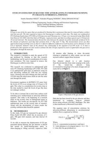
  • 1. 1 STUDY ON ESTIMATION OF RE-ENTRY TIME AFTER BLASTING IN UNDERGROUND MINING PT CIBALIUNG SUMBERDAYA, INDONESIA Sandro Hanaehan SIRAIT1 , Nuhindro Priagung WIDODO1 , Mikha SIMANJUNTAK2 1 Department of Mining Engineering, Faculty of Mining and Petroleum Engineering, Institut Teknologi Bandung, Indonesia 2 PT Cibaliung Sumberdaya, Indonesia Abstract CO gas is one of the few gases that are produced by blasting that is poisonous that must be removed before workers start the next job. The time required to remove the blasting gas is called re-entry time. The study was conducted at PT Cibaliung Sumberdaya (PT CSD) at Cibitung area and Cikoneng area. CO gas were measured using Riken Keiki Gas Detector GX-2003 which has limit of 500 ppm, 1 ppm precision, and data recording capacity up to 10 hours for 10-second intervals. The measured data showed the ratio between the amount of carbon monoxide produced (l) by the amount of explosives used (kg) had variation from 2.7 l/kg until 71 l/kg. The measurement curves are then approached using matching curve so that E or effective diffusion coefficient at each location can be obtained. E with L/d or hydraulic diameter ratio of the distance has relationship in the equation E=0.1595 (L/d) +5. E that is produced by that equation are later used to estimate the time CO gas required to reach 25 ppm before the gas exit to atmosphere through the main fan. I. INTRODUCTION This research is intended to study the spread of CO gas produced by blasting so that this research methodology can be used as consideration of re-entry time estimation. The time required to remove the blasting gas is called re-entry time. This research was conducted in underground gold mine PT Cibaliung Sumberdaya (PT CSD). PT CSD is an underground gold mine in Indonesia using cut and fill mining method. PT CSD has two mining areas: Cikoneng area and Cibitung area that each has 132 kW main fan which draws fresh air into the mine area through the portal. Government regulation in KEPMEN 555 states limit the levels of CO in an average time of 8 hours is 50 ppm. This value is a consideration for re-entry time or the time needed to reach the levels of gas that does not endanger workers. To be able to estimate the re-entry time, authors used matching curve method based on advection diffusion equation. This study is the beginning of a research study on the re-entry time in underground mines in Indonesia. The results are site-specific for PT CSD underground mine on the current state of research. Along with the development of mines results the existing ventilation data should be updated. II. METHODOLOGY In this study, CO gas are measured by gas detector Riken Keiki GX-2003 which has an accuracy of 1 ppm, 500 ppm limit measure, and time interval 10 seconds. To be able to measure the displacement of CO gas generated during blasting, the gas detector is placed and turned on before blasting takes place, ie when charging or filling activities explosives. After 30 minutes after blasting or when the smoke clearing is completed or when smoke was not seen anymore authors inspect these locations Gas detector placed in a safe location from flyrock and also from water seeping in the walls of the tunnel. Gas detector hung on wiremesh or longstrap to be stuck strongly and not easily fall as in Figure 1. Figure 1 Placement of the gas detector Data that has been stored by the gas detector and then transferred to computer using an infrared device using software GX-2003 datalogger. The data is then transferred to Microsoft Excel sheet. The equation state of concentration solutions for advection-diffusion phenomena in one-dimensional uniform flow is expressed as follows: √ ( ̅ ) Where, C (x, t) = concentration at position x and time t V = total substance in its original state (x = 0, t = 0) t = time after the gas produced (s)
  • 2. 2 A = cross-sectional area of the flow (m2 ) x = distance from the point of gas produced (m) ū = average velocity (m/s) E= effective diffusion coefficient The flowchart of this research is shown in Figure 2. Figure 2 Flowchart of this research III. DATA ANALYSIS 3.1 Profile of PT CSD Ventilation Systems Measurement of the quantity and distribution of air in the ventilation system of PT CSD are presented in Table 1 and Figure 3. Table 1 Distribution of the air quantity PT CSD No Description Air flow (m3 /s) Percentage 1 Intake air Portal Cikoneng 169.3 100% 2 Exhaust air a. Main Fan Cikoneng 86.3 50.97% b. Main Fan Cibitung 83 49.76% A) B) Figure 3 Percentage air flow distribution of PT CSD; (A) Air enters from Portal Cikoneng; (B) air exit through Cikoneng and Cibitung Shaft KEPMEN 555 regulates minimum air quantity based on the capacity of the machine and the number of employees that each work site underground mine requires 0.03 m3 /s for each employee and for each horse power of the diesel engine takes 0.05 m3 /s. Calculation of the minimum amount of air based activities are presented in Table 2. HP stated amount of horse power diesel engines and n states the number of workers. CKN means Cikoneng mining area. CBT means Cibitung mining area. Dec means decline area. Table 2 The amount of air flow required and supplied No Location Diesel Machine Type HP n Air Required (m3 /s) Air Supplied (m3 /s) 1 CKN 1135 LHD Caterpillar R1300 182 1 9.13 10.96 2 CKN 1065 LHD Atlas Copco Wagner 82 1 4.13 4.56 3 CKN 1120 Agi Truck Terex 152 1 7.63 8.34 4 CBT 1061 Shotcreter SIKA 74 2 3.77 2.25 5 CBT 1101 Backhoe Loader Caterpilar 87 1 4.38 3.45 6 CBT Dec Jumbo Drill Terex MK35HE 154 2 7.77 6.43 3.2 CO Gas Measurement Result Gas detector placed at a specific location in accordance with the location of the desired heading distance. Variation in the distance to the blasting face is made of at least 20 meters. Heading blasting in the area are Cikoneng and Cibitung area, as shown in Figure 4. Main ventilation scheme are shown in Figure 5. Measurements on the same heading with different distance variation performed at different blasting activities. Example of a measurement scheme blasting locations with distance variation is expressed in Figure 6. 182. 1 100 % Intake Air (m3/s) Portal Cikoneng 86.3 51%83 49% Exhaust Air (m3/s) Main Fan Cibitung Main Fan Cikoneng
  • 3. 3 Figure 4 CO Gas Measurement Scheme CO gas data were measured and plotted as a graph of concentration versus time. The chart shows Gaussian curve as shown in the example (1101 Cibitung area) in Figure 7. The gas detector has limit to measure CO that is 500 ppm, so that the data above limit can’t be detected. Authors predict that value using matching curve as we can see in figure below in [1101 CBT-1] curve line. Figure 7 Measurement results graphs From the available data, the amount of CO gas produced from any blasting can be obtained. The amount of CO gas produced to the amount of explosives are plotted in the graph is expressed in Figure 8. Figure 8 Number of explosives by the amount of CO gas Figure 5 PT CSD underground mine scheme 0 100 200 300 400 500 600 700 0 5 10 15 20 CO(ppm) Time (minute) 50 meter 115 meter 165 meter 0 500 1000 1500 2000 2500 3000 3500 4000 0 20 40 60 80 100 CO(l) Explosives (kg) [1101 CBT-1] CO Volume= 1,300,000 cc ū=0.37 m/s; L/d= 11.2 E=7 m2 /s [1101 CBT-2] CO Volume= 180,000 cc ū=0.39 m/s; L/d= 25.7 E=10 m2 /s [1101 CBT-3] CO Volume= 764,000 cc ū=0.55 m/s; L/d= 36.8 E=15 m2 /s
  • 4. 4 Figure 6 PT CSD main ventilation scheme The measured data showed the ratio between the amount of carbon monoxide produced (l) by the amount of explosives used (kg) had variation from 2.7 l/kg until 71 l/kg with the average ratio is 18.7 l/kg Because of that the amount of CO gas can not be predicted directly using data on the number of explosives. Further study is needed to consider additional factors that matter. The measured amount of CO gas does not have a strong relationship with the amount of explosives, so the amount of CO gas can not be predicted directly using data on the number of explosives. The measurement results show a very large variation and inconsistent values. Further study is needed to consider additional factors: a. Design geometry blasting b. Explosive compositions c. Absorption effect by wall or other material d. Additional gas from other sources. It could be a booster, primary, carbon-containing material, and the air before blasting begins e. Oxidation of CO gas into CO2 gas. 3.3 Effective Diffusion Coefficient In order to obtain the effective diffusion coefficient (E), authors used matching curve method which based on advection diffusion equation. Data is shown in Table 3. Table 3 Summary of effective diffusion coefficient No CO Measurement Station ū (m/s) E (m2 /s) Re L/d 1 1135 CKN-1 0.16 10.0 43983 11.2 2 1135 CKN-2 0.24 13.0 68954 22.3 3 1135 CKN-3 0.23 13.0 65265 73.7 4 1135 CKN-4 0.23 3.5 65265 90.4 5 1065 CKN-1 0.17 3.0 48239 6.7 6 1065 CKN-2 0.14 5.5 39726 12.3 7 1065 CKN-3 0.22 8.0 62427 22.3 8 1120 CKN-1 0.19 1.0 52496 4.5 9 1120 CKN-2 0.28 3.0 79453 63.6 No CO Measurement Station ū (m/s) E (m2 /s) Re L/d 10 1061 CBT-1 0.24 5.2 68102 13.4 11 1061 CBT-2 0.18 10.0 51077 39.1 12 1061 CBT-3 0.24 11.0 68102 49.1 13 1101 CBT-1 0.37 7.0 104991 11.2 14 1101 CBT-2 0.39 10.00 110666 25.7 15 1101 CBT-3 0.55 15.0 156068 36.8 16 DEC CBT-1 0.23 10.00 65265 8.9 17 DEC CBT-2 0.30 25.00 85128 17.9 Relationship effective diffusion coefficient, E, with L/d is expressed in Figure 9. From relationship between E with L/d can be concluded that L/d can be a parameter to estimate the value of E. With L/d values about 100 the empirical equation E=0.1595 (L/d). The reason can be considered that the L/d represents bends, branches, and other obstacles along the tunnel shape. For health and safety considerations, it is necessary corrections so that the largest value is used as a reference. So the equation become E* = 0.1595 (L/d) + 5. Figure 9 Graph E to L / d E = 0.1595 (L/d) E* = 0.1595 (L/d) + 5 0 5 10 15 20 1 10 100 E(m2/s) L/d E vs L/d E E*
  • 5. 5 3.4 Re-entry Time Estimation Using equation E*, E values are obtained 22.09 at Cikoneng area and 23.16 at Cibitung area, value of Cikoneng average speed is 0.21 m/s and Cibitung 0.31 m/s, along with the largest amount of CO gas 3,550,000 cc are all put into advection diffusion equations to estimate the re-entry time in each area. Re-entry time is considered a time to reach the safety limit (in this study 25 ppm) of CO gas. Distance used in Cikoneng 480 m (L/d=107.1) and Cibitung 510 m (L/d=113.8). Value of 25 ppm is used as the application of a safety factor of 2. The curves show that re-entry time Cikoneng area takes 118 minutes and Cibitung area 72 minutes. Curve simulation results are expressed in Figure 10. Figure 10 Re-entry time estimation of Cikoneng and Cibitung area IV. CONCLUSIONS REMARKS Measured CO gas curve is needed to evaluate gas transportation in underground mine, especially to evaluate flammable and toxic gas. In this study authors tried to evaluate E or effective advection diffusion coeffisient that later are used to estimate re- entry time. Further research about this topic, estimation of re-entry time in underground mine, are still needed. In this study authors only consider CO gas and ignore the presence of other gas that may be harmful to worker’s health. Improvement of the gas detector is important. The actual data about CO gas should be collected regularly based on the development of underground mine to estimate re- entry time. Recommmendation for advance study about this topic are to conduct further experiments with numerical method to take into account airways variations and consider several curves representing variation of effective coefficient diffusion in each lane. Second, conduct research to measure CO by considering additional factors mentioned before. ACKNOWLEDGEMENTS Authors would like to thank PT Cibaliung Sumberdaya; Mr Sinambela, Mr Agus Sudarto, Mr Haris, Mr Purwoko, and Mr Nopian. Also to all lecturer and staff in Mining Engineering Program ITB, especially to Dr. Eng. Syafrizal, ST, MT as the head of Mining Department in ITB. REFERENCES Chaiken, R. F., Cook, E. B., Ruhe, T. C. 1974. Toxic Fumes from Explosives: Ammonium Nitrate-Fuel Oil Mixtures, U. S. Bureau of Mines, Washington. De Souza, E. M dan Katsabanis, P. D. 1991. On the Prediction of Blasting Toxic Fumes and Dilution Ventilation. Min. Sci. Technol. 13: 223-235. Gillies, A. D. S., Wu, H. W., & Shires, D. 2004. Development of an Assessment Tools to Minimize Safe After Blast Re-entry Time to Improve the Mining Cycle. Harris, M.L., Sapko, M. J., Mainiero, R. J. 2003. Toxic Fume Comparison of A Few Explosives Used in Trench Blasting. NIOSH Pittsburgh Research Laboratory. Hartman, H.L., Mutmansky, J., Ramani, R., Wang, Y.J. 1997. Mine Ventilation and Air Conditioning, John Wiley & Sons. Keputusan Menteri Pertambangan dan Energi nomor 555.K/26/M.PE/1995 Keselamatan dan Kesehatan Kerja Pertambangan Umum Mainiero, R. J. 1997. A Technique for Measuring Toxic Gases Produced by Blasting Agents. Mainiero, R. J, Harris, M. L, Rowland III, J. H. Dangers of Toxic Fumes from Blasting. McPherson, M.J. 1997. Subsurface Ventilation and Environmental Engineering, Chapman & Hall. Rowland III, J. H, dan Mainiero, R. 2000. Factors Affecting ANFO Fumes Production Widodo, N. P., Sasaki, K. & Sugai, Y., Sayoga, R. S. 1998. Turbulent diffusion coefficient in mine airways. Wieland, M. S. 1997. Work Principle for Predicting Explosive Toxic Fumes. 0 50 100 150 200 250 300 0 10 20 30 40 50 60 70 80 90 100 110 120 130 140 150 160 170 180 CO(ppm) Time (Minute) Cikoneng Cibitung Vol CO= 3.550.000 cc L/d= 107.1; ū=0.21 m/s E= 22.09; Time= 118 minutes Vol CO= 3.550.000 cc L/d= 113.8; ū=0.31 m/s E= 23.16; Time= 72 minutes