Space Technology A Short Introduction Ignacio Chechile
Space Technology A Short Introduction Ignacio Chechile
Space Technology A Short Introduction Ignacio Chechile
Space Technology A Short Introduction Ignacio Chechile
Space Technology A Short Introduction Ignacio Chechile
1.
Read Anytime AnywhereEasy Ebook Downloads at ebookmeta.com
Space Technology A Short Introduction Ignacio
Chechile
https://ebookmeta.com/product/space-technology-a-short-
introduction-ignacio-chechile-2/
OR CLICK HERE
DOWLOAD EBOOK
Visit and Get More Ebook Downloads Instantly at https://ebookmeta.com
2.
Recommended digital products(PDF, EPUB, MOBI) that
you can download immediately if you are interested.
Space Technology: A Short Introduction Ignacio Chechile
https://ebookmeta.com/product/space-technology-a-short-introduction-
ignacio-chechile/
ebookmeta.com
NewSpace Systems Engineering 1st Edition Ignacio Chechile
https://ebookmeta.com/product/newspace-systems-engineering-1st-
edition-ignacio-chechile/
ebookmeta.com
Music and Technology: A Very Short Introduction Mark Katz
https://ebookmeta.com/product/music-and-technology-a-very-short-
introduction-mark-katz/
ebookmeta.com
Solving Cold Cases Vol 5 True Crime Stories that Took
Years to Crack True Crime Cold Cases Solved 1st Edition
Andrew J. Clark
https://ebookmeta.com/product/solving-cold-cases-vol-5-true-crime-
stories-that-took-years-to-crack-true-crime-cold-cases-solved-1st-
edition-andrew-j-clark/
ebookmeta.com
3.
Sassy's Desired Mate(Olympic Wolves Book 2) 1st Edition
Pa Vachon [Vachon
https://ebookmeta.com/product/sassys-desired-mate-olympic-wolves-
book-2-1st-edition-pa-vachon-vachon/
ebookmeta.com
Beginning EJB 3: Java EE 7 Edition Jonathan Wetherbee
https://ebookmeta.com/product/beginning-ejb-3-java-ee-7-edition-
jonathan-wetherbee/
ebookmeta.com
Conceptualising Procedural Fairness in EU Competition Law
1st Edition Haukur Logi Karlsson
https://ebookmeta.com/product/conceptualising-procedural-fairness-in-
eu-competition-law-1st-edition-haukur-logi-karlsson/
ebookmeta.com
Being the Change Live Well and Spark a Climate Revolution
1st Edition Kalmus Peter
https://ebookmeta.com/product/being-the-change-live-well-and-spark-a-
climate-revolution-1st-edition-kalmus-peter/
ebookmeta.com
The Reception of Du Fu 712 770 and His Poetry in Imperial
China 1st Edition Ji Hao
https://ebookmeta.com/product/the-reception-of-du-fu-712-770-and-his-
poetry-in-imperial-china-1st-edition-ji-hao/
ebookmeta.com
4.
Science of LifeAfter Death 1st Edition Alexander Moreira-
Almeida
https://ebookmeta.com/product/science-of-life-after-death-1st-edition-
alexander-moreira-almeida/
ebookmeta.com
Contents
1 Introduction
1.
1 Spaceand Startups, a.
k.
a “NewSpace”
2 Artificial Satellites; The Shortest Introduction Ever
3 Semiconductors in Space:From Sand to Satellites
3.
1 Let’s Meet at the Junction
3.
2 The Transistor Drama
3.
3 The Space Environment
3.
3.
1 Unpacking Single Event Effects (SEEs)
4 The Hectic Ride to Space
4.
1 Rideshares, Dispensers, and Orbital Transfer Vehicles
5 Configuring Spacecraft
6 A Peek Under the Hood
6.
1 The Skeleton:Structures and Mechanisms
6.
2 The Data Links:From Sparks to Mobile Networks, Lasers,
and In-Orbit Networks
6.
2.
1 Mobile Networks and Satellites
6.
2.
2 Lasers in Orbit
6.
2.
3 Connectivity
6.
3 The Software:Hello World in Space
6.
3.
1 What Does It Take to Run Software on a Spacecraft?
6.
3.
2 How Is Software Updated or Changed in Orbit?
6.
3.
3 What Type of Languages Are Used for Coding Flight
Software?
6.
3.
4 Can I Run Linux on a Satellite?What About Windows?
6.
3.
5 Can I Host a Website on a Satellite?
10.
6.
3.
6 What Kindof Skills Are Required for Doing Flight
Software?
6.
3.
7 How Is Flight Software Designed?
6.
3.
8 What Does “Software-Defined Satellites” Mean?
6.
3.
9 Bugs and Glitches in Orbit
6.
4 The Orientation:Attitude Control
6.
5 The Space Sauna:Thermal Control
6.
6 The Avionics
6.
7 The Payload
6.
8 Putting It Together:Assembly, Integration and Test
6.
8.
1 Mechanical Tests
6.
8.
2 Thermal Vacuum Test (TVAC)
6.
8.
3 Software Verification
6.
8.
4 Concluding and Shipping
7 Satellites and Machine Learning
7.
1 Can There Be Too Much Data?
8 Operating Distant Machines Floating in Space
9 Making Reliable and Dependable Spacecraft
10 TL:
DR; Frequently Asked Questions About Space
10.
1 Q0:Why Launch a Metal Box into Space?
10.
2 Q1:What Are the Rules for Launching Something into
Space?
10.
3 Q2:How Are Satellites Designed and Developed?Also, Is It
Done Differently in NewSpace Versus Classic Space?
10.
4 Q3:What’s Typically Under the Hood of a Satellite?
10.
5 Q4:How Are Satellites Launched?
10.
6 Q5:Ok the Thing Is up in Space, Now What?
11.
10.
7 Q6:How DoSatellites Orient Themselves in Space?
10.
8 Q7:How Are Satellites Operated?
10.
9 Q8:What Does the Software on Board of a Satellite Do
Exactly?
10.
10 Q9:How Do Satellites Generate Power?
10.
11 Q10:How Big and Heavy Are Current Commercial
Satellites?
10.
12 Q11:What Is the Lifetime of a Satellite?
10.
13 Q12:What Can Affect the Lifetime of a Satellite?
10.
14 Q13:What Is an Orbit Exactly?
10.
15 Q14:Why Are Orbits Crowded and How Is This an Issue?
10.
16 Q15:Why Are Satellites Assembled in Clean Rooms?
10.
17 Q16:How Are Satellites Currently Distributed Across
Different Orbits?
12.
List of Figures
Fig.2.
1Newton’s cannon
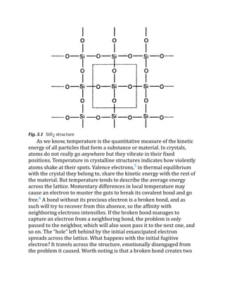
Fig. 3.1 SiO2 structure
Fig.3.
2 A bipolar transistor with one junction in forward-bias and
another one in reverse-bias
Fig.3.
3 NOT gate with BJT transistor
Fig.3.
4 NAND gate with BJT transistor
Fig.3.
5 Van Allen radiation belts; cross them is not the nicest ride for a
satellite going somewhere (public domain)
Fig.3.
6 Magnetic field strength at Earth’s surface (Creative Commons)
Fig.3.
7 Applicability of SEE to different device types
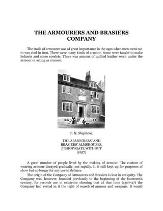
Fig.6.
1 Junkers J 1 (public domain)
Fig. 6.2 Subsystem faults and types of faults. Source Fault-Tolerant
Attitude Control of Spacecraft (Qinglei Hu, Bing Xiao, Bo Li, Youmin
Zhang)
13.
Fig. 6.3 Typesof faults in the attitude control subsystem. Source Fault-
Tolerant Attitude Control of Spacecraft (Qinglei Hu, Bing Xiao, Bo Li,
Youmin Zhang)
Fig.6.
4 Funny little configuration to have by default
Fig.6.
5 Good luck running for the tram in Helsinki without friction
forces (Creative Commons)
Fig. 6.6 FA and FB are forces applied at different distances from the
center O, creating different torques. Credit public domain
Fig.6.
7 Building blocks of a computer-based control system
Fig.6.
8 A generic avionics block diagram
Fig.6.
9 AOCS functional chain as a member of the avionics architecture
Fig.6.
10 Subsystem federated architecture with a star topology
Fig.6.
11 A backplane connecting 1 CPU unit and 2 peripheral boards
Fig.7.
1 An unannotated graph
Fig.7.
2 Google searches over time about something unspecified
14.
Fig.7.
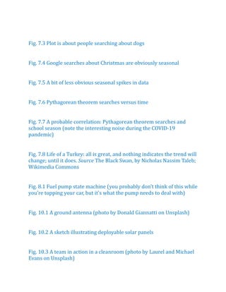
3 Plot isabout people searching about dogs
Fig.7.
4 Google searches about Christmas are obviously seasonal
Fig.7.
5 A bit of less obvious seasonal spikes in data
Fig.7.
6 Pythagorean theorem searches versus time
Fig.7.
7 A probable correlation:Pythagorean theorem searches and
school season (note the interesting noise during the COVID-19
pandemic)
Fig. 7.8 Life of a Turkey: all is great, and nothing indicates the trend will
change; until it does. Source The Black Swan, by Nicholas Nassim Taleb;
Wikimedia Commons
Fig.8.
1 Fuel pump state machine (you probably don’t think of this while
you’re topping your car, but it’s what the pump needs to deal with)
Fig.10.
1 A ground antenna (photo by Donald Giannatti on Unsplash)
Fig.10.
2 A sketch illustrating deployable solar panels
Fig.10.
3 A team in action in a cleanroom (photo by Laurel and Michael
Evans on Unsplash)
15.
Fig.10.
4 Distribution ofsatellites for altitudes between 0 and 50,000
km altitude
Fig.10.
5 Distribution of satellites for altitudes between 0 and 2000 km
(LEO)
Fig.10.
6 Distribution of satellites for altitudes between 400 and 700
km (LEO)
What is theprocess to design and build satellites?
How do people on the ground keep track of satellites as they fly?
What happens if a satellite fails?
What kind of data do satellites deal with?
This short guide got your back. When you finish reading these lines,
you will be equipped with a good dose of the fundamentals about the
peculiar endeavor of creating artificial satellites. Moreover, you will also
get an idea about the technologies that have enabled—and keep
enabling—space activities, like materials, radio, telecommunications,
optics, and software, with some brief historical background provided
whenever possible. But beware: this is not a handbook, nor a doctoral
thesis. The depth of the topics overall is at the introductory level. I tried
on purpose not to bloat this text with distracting figures and focus on
content and fundamentals. This is nothing but a primer. If any section in
this text interests you more than any other, I trust you will do a deeper
research using the links provided. Google is your friend. Of course, once
you land if you happen to be flying while reading.
1.1 Space and Startups, a.k.a “NewSpace”
Lately, space technology has been happening at the dungeons of very
small and dynamic companies: space startups. Life in startups is quite
well documented, perhaps somewhat over documented and a tad
romanticized. There are books, blogs, and popular TV series. Startup
platitudes are all over the place in social media—everyone seems to
know how to run them, how to scale them, adding their own bit of
advice, their own experiences of what works, what doesn’t. Although
most startups more or less go through similar phases, in reality each
one of them is unique. No surprise there: the same applies for
us people; we all go through the same life stages, from infancy to
adolescence and adulthood, although we all—luckily—experience each
of these life cycle stages very differently.
Space startups are a subset of the startup universe, yet a peculiar
type. What’s so special about them? Think about a space startup for a
moment. A handful of people trying to build spaceships, on hair-thin
budgets, short runways (bankruptcy is constantly lurking around the
corner), and often without having a customer in sight. There isn’t
18.
perhaps another startuptype with so many odds against, just by
looking at the challenges they face. In a way, space startups are like
salmon. Salmon swim against the river's current the whole way—
sometimes up to thousands of kilometers, leaping over obstacles,
waterfalls, rapids, and dams. These amazing fish can jump two meters
high or even higher. And all while hungry predators like bears and
eagles wait around every river bend to catch them when they jump out
of the water. Just like salmon, many space startups will perish along the
way. But a fair lot will make it up the river, in the process becoming
what Nicolas Nassim Taleb calls “antifragile”—what doesn’t kill them
makes them stronger—and eventually reaching orbit. Antifragility is a
property of systems in which they increase their probability of survival
as a result of shocks, volatility, mistakes, faults, attacks, or failures. For
antifragile space startups, an extra day they exist, the higher the
chances of continuing existing.
When analyzing space startups, survivorship bias1
is a trap we
repeatedly fall into. For each startup that makes it big, there are
thousands of others who didn’t make it and have volumes to speak but
die in silence. In terms of survivability, there is more insight from the
salmon who did not make it up the river than from those that did, for
the former knows what didn’t work—where the bears are lurking—
whereas the latter could have been just lucky. Granted, a dead salmon
can't talk. Also live salmon can't talk, but you get the gist of the analogy.
What’s inside a space startup if you crack it open? How can a small
bunch of people get to launch something into space? Wasn’t space
supposed to be done by governmental agencies, with their billion-
dollars budgets, their thousands of employees, their bureaucracy? No.
You can get to fly something in space with, say, less than 10 people and
a modest budget. How? The magic tends to revolve around vision,
motivation, industrial loads of hard work, commitment, and an
obsessively systemic mindset. Yes, this sounds like yet another of those
platitudes out of a vanity-published management book sold in airport
bookstores. But there is no magic and it all boils down to common
sense and few things to pay attention whenever possible.
The first one is complexity. Designing a satellite is a complex task. If
you open the hood of any satellite, what you will see is an intricate
network of computers, each one performing a specialized job—
19.
command and datahandling, attitude control, radio communications,
payload control, data processing, etc. Each computer is a world on its
own, running lots of software. Making sure those “worlds” combine
seamlessly in order to give a spacecraft its functional integrity in a
harmonic way requires a good deal of cross-functional and system level
analysis such as architecture design, thermal analysis, structural
analysis, power generation, physical configuration, and a very long et
cetera. What’s more, all those things are heavily intertwined. Such
interdisciplinary is nothing else than Systems Engineering,2
which
more a craft than a profession. The good thing is that it does not require
you hiring a veteran Systems Engineering wizard you couldn’t possibly
dream to afford. In fact, Systems Engineering is a glorified term for a
combination of good knowledge of the technical fundamentals, critical
thinking, problem solving and common sense. Although these factors
do improve with experience, there’s plenty of young people with a good
dose of them.
The second one is wheel reinvention (the avoidance thereof). One of
the most important factors in small space startups is to minimize
rediscovering said round artifact used to help things move from A to B.
This also means, space startups must stay extremely focused on what
their métier is. Mind you, the métier may change along the way and the
space startups that prevail are those who identify in time when the
focal point is wrong and are able to swerve before the iceberg gets too
close.
The third one. The not-so-glamorous side of building things: supply
chain. The grocery list. Supply chain management is an art. It deals with
uncertainty, change, prices, inflation, secrecy, proprietary data,
volatility, convoluted technical specifications, variants, and a ridiculous
amount of foresight to predict what a company will manufacture years
from now. Supply chain is a challenging endeavor when you are small,
young, and the new kid on the block. Suppliers tend to pay attention to
the big guns—their established customers—and rightly so; who could
blame them? Then, the small guys must elbow their way to source
themselves parts and components, at times closing partnerships with
other fellow young startups in need. In NewSpace, John Does attract
Jane Does.
20.
In the process,some space startups may choose to maverick their
make vs buy strategy and go vertical or in-house, supposedly to shield
themselves from supplier uncertainty, only to continue being locked in
with suppliers because they realize they cannot produce up to the last
bolt. On the flip side, horizontal integration may create uncomfortable
situations if a critically important, complex subsystem is provided by a
third party in which the startup has zero control (and sometimes zero
trust).
Fourth one, the almost literally million-dollar question: what on
earth to sell. Next time you walk past a pizza place, think about how
clear the product is for them. They make pizzas, that’s what they sell.
Simple as that. Zero ambiguity. They define flavors, toppings, variants.
They choose names for the variants and print menus. They make
people happy by selling warm flat tasty discs with cheese, tomato sauce
and stuff. It’s so clear that if you go and ask anyone working there what
it is that they sell, they will all say the same: we sell pizza—what a silly
question to ask! Now, for a visitor entering the office of a space startup
and picking up someone from the team and asking: what the hell is this
startup selling, the answer may vary depending on who the mysterious
visitor should ask. That’s the situation usually at the early—and not so
early—stages: an amorphous idea involving space technology does not
always automatically map to a product. It can be data, can be insight
from the data, can be the spacecraft, can be a subsystem, can be a
service on top of all that. Products must be discovered, and such
discovery process may take long and be exhausting. Ideally, the product
shall be discovered before the money runs out.
And fifth, last and perhaps the most important thing: everyday life.
A space startup is not just a romantic adventure about reaching the
stars. Or, it might be, but reaching the stars comes as the culmination of
disciplined work and sound day-to-day company operations as people
share many hours a week, shoulder to shoulder, overcoming hurdles
and finding their way through the job. In short, a space startup is—no
surprise there—an actual company which needs to be run. There are
operational matters such as talent capture, facility management, frozen
pizza, coffee, and of course, team matters. Building healthy teams
where learning and making mistakes is part of the job and, more
fundamentally, where it is fun to do all that is a bigger accomplishment
21.
than flinging shinyboxes beyond the Kármán line.3
All this is what
NewSpace startups are about. Satellites, at the end of the day, are by-
products. The main ‘product’ of a space startup is the network of brains
behind the technology.
So, let’s dive into this. The chapters of this text are reasonably self-
contained, although there might be suggestions in certain parts to jump
here and there for elaboration. I do not expect you to read this from
cover to cover, but to selectively sift through the pages as the topics that
resonate on you and your curiosity will capture your attention. Some
chapters go a bit more technical than others, and if the content in those
makes absolutely no sense, jump back to the safety of the less technical
sections. If you are really, really busy, there is a TL; DR (too long, didn’t
read) chapter at the end (Chap. 10) which summarizes the text in a set
of frequently asked questions.
As a CTO at a space startup like ReOrbit, I am responsible for
ensuring that the technology roadmap comes together and aligns well
with the business model. But my job is, as I see it, more than that.
Fundamentally, as a CTO, my role is to ensure the team of engineers I
lead enjoy developing space technology and feel safe trying things out
and screwing up in the process, learning from the mistakes and
charging back stronger than before. There is no innovation possible
without experimentation, and space technology moves forward thanks
to those who venture themselves into the unknown, for most of the
‘knowns’ today in space were unknowns yesterday.
Last but definitely not least, a mention of ReOrbit. ReOrbit is a space
company based in Helsinki, Finland, and with offices in Stockholm and
Argentina. Founded in 2019, ReOrbit designs and develops satellites for
a variety of different payloads and applications. At ReOrbit, satellites
are designed as network routers and thus equipped with the
capabilities to ensure secure and reliable data transport from satellite
to satellite or satellite to ground. Find more information at www.
reorbit.
space.
With all this being said, here we go.
Ignacio Chechile, Chief Technology Officer, ReOrbit. April 2023.
Helsinki, Finland.
22.
1
2
3
Footnotes
Survivorship bias isthe logical error of concentrating on entities that passed a
selection process while overlooking those that did not. This can lead to incorrect
conclusions because of incomplete data.
Systems engineering is an interdisciplinary field of engineering and engineering
management that focuses on how to design, integrate, and manage complex systems
over their life cycles. At its core, systems engineering utilizes systems thinking
principles to organize its body of knowledge. The individual outcome of such efforts,
an engineered system, can be defined as a combination of components that work in
synergy to collectively perform a useful function.
The Kármán line is a proposed conventional boundary between Earth's
atmosphere and outer space set by the international record-keeping body FAI
(Fédération Aéronautique Internationale) at an altitude of 100 km. However, such
definition of the edge of space is not universally adopted.
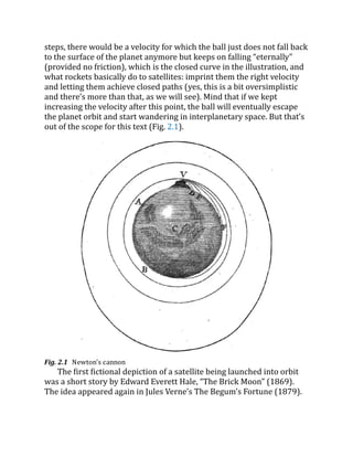
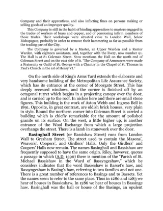
steps, there wouldbe a velocity for which the ball just does not fall back
to the surface of the planet anymore but keeps on falling “eternally”
(provided no friction), which is the closed curve in the illustration, and
what rockets basically do to satellites: imprint them the right velocity
and letting them achieve closed paths (yes, this is a bit oversimplistic
and there’s more than that, as we will see). Mind that if we kept
increasing the velocity after this point, the ball will eventually escape
the planet orbit and start wandering in interplanetary space. But that’s
out of the scope for this text (Fig. 2.1).
Fig. 2.1 Newton’s cannon
The first fictional depiction of a satellite being launched into orbit
was a short story by Edward Everett Hale, “The Brick Moon” (1869).
The idea appeared again in Jules Verne’s The Begum’s Fortune (1879).
25.
In 1903, KonstantinTsiolkovsky published Exploring Space Using Jet
Propulsion Devices, which is the first academic treatise on the use of
rocketry to launch spacecraft.
Herman Potočnik entertained the idea of using orbiting spacecraft
for detailed peaceful and military observation of the ground in his 1928
book, The Problem of Space Travel. He described how the special
conditions of space could be useful for scientific experiments. The book
described geostationary satellites (first put forward by Tsiolkovsky)
and discussed communication between them and the ground using
radio but fell short of the idea of using satellites for mass broadcasting
and as telecommunications relays.
In a 1945 Wireless World article, the English science fiction writer
Arthur C. Clarke described in detail the possible use of communications
satellites for mass communications. He suggested that three
geostationary satellites would provide coverage over the entire planet.
In May 1946, the United States Air Force’s Project RAND released
the Preliminary Design of an Experimental World-Circling Spaceship,
which stated “A satellite vehicle with appropriate instrumentation can
be expected to be one of the most potent scientific tools of the
Twentieth Century”. The United States had been considering launching
orbital satellites since 1945 under the Bureau of Aeronautics of the
United States Navy.
In 1946, American theoretical astrophysicist Lyman Spitzer
proposed an orbiting space telescope.
In February 1954, Project RAND released “Scientific Uses for a
Satellite Vehicle”, by R. R. Carhart. This expanded on potential scientific
uses for satellite vehicles and was followed in June 1955 with “The
Scientific Use of an Artificial Satellite”, by H. K. Kallmann and W. W.
Kellogg.
In the context of activities planned for the International Geophysical
Year (1957–1958), the White House announced on 29 July 1955 that
the U.S. intended to launch satellites by the spring of 1958. This became
known as Project Vanguard. On 31 July, the Soviet Union announced its
intention to launch a satellite by the fall of 1957. The game was on.
The first real artificial satellite would end up being Sputnik 1,
launched by the Soviet Union on 4 October 1957 under the Sputnik
program. The 84 kg spacecraft worked for roughly 2 weeks, and it
26.
reentered the atmospherea few months after. Its architecture was
rather rudimentary: its batteries weighed 51 kg, it was equipped with a
1Watt transmitter which encoded telemetry in low frequency pulses
which would be broadcast and heard on AM radio, and it was
pressurized with nitrogen.
Sputnik 1 helped to identify the density of high atmospheric layers
through measurement of its orbital change and provided data on radio
signal distribution in the ionosphere. The unanticipated announcement
of Sputnik 1’s success precipitated the Sputnik crisis in the United
States and ignited the so-called Space Race within the Cold War.
Sputnik 2 was launched on 3 November 1957 and carried the first
living passenger into orbit, a dog named Laika.
Explorer 1 became the United States’ first artificial satellite,
launched on 31 January 1958. The information sent back from its
radiation detector led to the discovery of the Earth’s Van Allen radiation
belts. The TIROS-1 spacecraft, launched on April 1, 1960, as part of
NASA’s Television Infrared Observation Satellite (TIROS) program, sent
back the first television footage of weather patterns to be taken from
space.
In June 1961, three and a half years after the launch of Sputnik 1,
the United States Space Surveillance Network had already cataloged
115 Earth-orbiting satellites. Things escalated really quick.
Expectedly, early satellites were built to unique designs. With
advancements in technology, multiple satellite missions began to be
built on single model platforms called satellite buses. The first
standardized satellite bus design was the HS-333 geosynchronous
(GEO) communication satellite made by Hughes and launched in 1972.
Oddly enough, many satellites are still designed and built as one offs—
in other words, the 70s way—although multi-mission buses are
growing in popularity. We will talk about this in due time.
As of today, there are more than 5000 operative satellites orbiting
our planet. If we count both operative and inoperative spacecraft,
forgotten stages of rockets and whatnot, we need to talk about 10,000
objects flying over our heads.
Since Sputnik 1, satellite architecture and design methods have
evolved consistently. Satellites’ capabilities have improved fast thanks
to the progress certain enabling technologies have made on their own.
27.
One of thosefoundational technologies stand out from the rest:
semiconductors. Let’s talk about that in the next chapter.
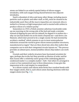
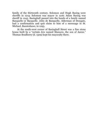
atoms are linkedin an orderly spatial lattice of silicon-oxygen
tetrahedra, with each oxygen being shared between two adjacent
tetrahedra.
Sand is abundant of silica and many other things, including macro
particles such as plastic and other stuff, so SiO2 must be cleaned to be
industrially used. Once all the macro impurities are removed, silica is
melted in a furnace at high temperature and is reacted with carbon to
produce silicon of a relative purity.1
Somewhere in 1915 a Polish scientist called Jan Czochralski woke
up one morning on the wrong side of the bed and made a mistake:
instead of dipping his pen into his inkwell, he dipped it in molten tin—
why our Jan had molten tin on his desk is beyond me—and drew a tin
filament, which later proved to be a single crystal. He had invented by
accident a method2
which remains in use in most semiconductor
industries around the world to grow silicon monocrystalline structures,
manufactured as ingots3
that are then sliced into ultra-thin wafers that
companies use to etch their integrated circuits layouts on.4
The process
provides an almost pure, monocrystalline silicon chip makers can work
with.
Crystals and their orderly structure have fascinated scientists for
ages, perhaps due to the fact they provide an illusion of order and for
that reason offer a relatively easier grasp of the underlying physics:
condensed matter is a complex matter—heh—but when it’s arranged in
a more or less symmetrical way in three dimensions, it may give the
impression to be a tad simpler to comprehend.
In a silicon crystal, each silicon atom forms four covalent bonds with
four oxygen atoms, that is, each silicon atom sharing electrons with four
oxygen atoms (see Fig. 3.1).
30.
Fig. 3.1 SiO2structure
As we know, temperature is the quantitative measure of the kinetic
energy of all particles that form a substance or material. In crystals,
atoms do not really go anywhere but they vibrate in their fixed
positions. Temperature in crystalline structures indicates how violently
atoms shake at their spots. Valence electrons,5
in thermal equilibrium
with the crystal they belong to, share the kinetic energy with the rest of
the material. But temperature tends to describe the average energy
across the lattice. Momentary differences in local temperature may
cause an electron to muster the guts to break its covalent bond and go
free.6
A bond without its precious electron is a broken bond, and as
such will try to recover from this absence, so the affinity with
neighboring electrons intensifies. If the broken bond manages to
capture an electron from a neighboring bond, the problem is only
passed to the neighbor, which will also soon pass it to the next one, and
so on. The “hole” left behind by the initial emancipated electron
spreads across the lattice. What happens with the initial fugitive
electron? It travels across the structure, emotionally disengaged from
the problem it caused. Worth noting is that a broken bond creates two
31.
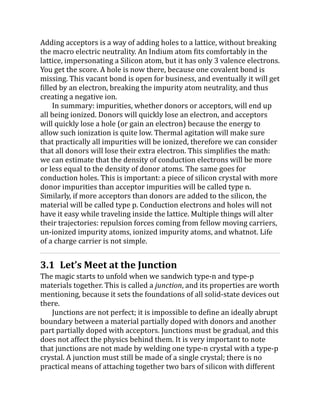
phenomena: wandering holesand wandering free electrons. Another
way of calling such free electrons is conduction electrons.
Undisputed kings of negative charge, electrons leave positively
charged zones behind them. Therefore, in the vicinity of holes, the
charge is now more positive, and such positivity travels as the hole
travels. Therefore, we can say holes have positive charge.
A wafer of pure monocrystalline silicon or germanium does not do
much in and of itself. It is just an ‘intrinsic’ material with electrons and
holes moving around because of bonds constantly being broken due to
thermal agitation. Intrinsic materials create electron–hole pairs in exact
numbers because one exists because of the other (along with some
other particles existing inside intrinsic silicon as well, like photons).
Intrinsic materials would be of little practical use if we couldn’t break
the balance between electrons and holes. How to break that harmony?
By opportunistically sprinkling our crystals with more electrons (or
more holes) by means of adding impurities. Didn’t we say impurities
were bad? Yes, but these are more sophisticated, controlled impurities,
unlike the microplastic that washes ashore on beaches as a product of
our pointless mass consumption urges.
But here’s the catch: we cannot just add loose electrons like we add
pepper to salad—the Coulomb forces would be insane due to the
sudden electric charge imbalance. All we can do is to add atoms that
can contribute with electrons, called donors. Examples of donors are
phosphorus or arsenic. Typical proportions of impurity atoms is one of
these guys for every million silicon atoms.
When a donor atom is implanted in the lattice, it mimics the Si atom
quite well; it completes the four covalent bonds the same way as Si
atoms do. But arsenic happens to have 5 valence electrons, so one
electron does not belong to any bond, and because it’s not trapped in
any potential barrier, it has a higher energy than their other 4 cousins,
and thus it has high chances of leaving the atom behind, leaving it
positively charged as a gift. An ion is born, fixed in the crystalline
structure. The material remains electrically neutral at the macro level,
but it’s now populated with positively charged spots, all balanced by
the free electrons wandering around.
Conversely, acceptor impurities do the opposite. Aluminum, Indium
and Gallium, for instance, are good examples of acceptor elements.
32.
Adding acceptors isa way of adding holes to a lattice, without breaking
the macro electric neutrality. An Indium atom fits comfortably in the
lattice, impersonating a Silicon atom, but it has only 3 valence electrons.
You get the score. A hole is now there, because one covalent bond is
missing. This vacant bond is open for business, and eventually it will get
filled by an electron, breaking the impurity atom neutrality, and thus
creating a negative ion.
In summary: impurities, whether donors or acceptors, will end up
all being ionized. Donors will quickly lose an electron, and acceptors
will quickly lose a hole (or gain an electron) because the energy to
allow such ionization is quite low. Thermal agitation will make sure
that practically all impurities will be ionized, therefore we can consider
that all donors will lose their extra electron. This simplifies the math:
we can estimate that the density of conduction electrons will be more
or less equal to the density of donor atoms. The same goes for
conduction holes. This is important: a piece of silicon crystal with more
donor impurities than acceptor impurities will be called type n.
Similarly, if more acceptors than donors are added to the silicon, the
material will be called type p. Conduction electrons and holes will not
have it easy while traveling inside the lattice. Multiple things will alter
their trajectories: repulsion forces coming from fellow moving carriers,
un-ionized impurity atoms, ionized impurity atoms, and whatnot. Life
of a charge carrier is not simple.
3.1 Let’s Meet at the Junction
The magic starts to unfold when we sandwich type-n and type-p
materials together. This is called a junction, and its properties are worth
mentioning, because it sets the foundations of all solid-state devices out
there.
Junctions are not perfect; it is impossible to define an ideally abrupt
boundary between a material partially doped with donors and another
part partially doped with acceptors. Junctions must be gradual, and this
does not affect the physics behind them. It is very important to note
that junctions are not made by welding one type-n crystal with a type-p
crystal. A junction must still be made of a single crystal; there is no
practical means of attaching together two bars of silicon with different
33.
impurities dosage andexpect that it will work. The crystal lattice
perfection is a key factor when it comes to junction’s performance.
In equilibrium (that is, with the piece of silicon that hosts the
junction at some nonzero temperature, with no electric field applied),
the concentration of acceptors will be maximum on the p-side, then
decrease to zero as we approach the junction, and the same for donors
on the n-side. With carriers moving due to thermal agitation, they cross
the boundary thrusted by the gradient of impurities concentrations at
the far ends. Holes come across the chasm and reach to the n-side,
where they recombine easily because of the high density of electrons
there. Equivalently, electrons cross the boundary to the p side, and
recombine. Then, a zone starts to appear around the border, a zone
without carriers. A no man’s land of sorts, where all ions are complete.
Because acceptor and donor ions are fixed to the lattice, the area
around the boundary will be charged slightly negative on the p side
(because electrons have found their spots in acceptors) and slightly
positive on the n side, because electrons have fled the scene. These non-
zero charge levels stemming from the fixed ions create an electric field,
which causes the diffusion process to settle when such electric field is
intense enough to create displacement currents that cancel further
currents from the doping concentration gradient.
In all our analyses thus far, we have only considered the piece of
material to be only interacting with its surroundings by thermal energy.
But that is only one part of the story. There are several other ways
equilibrium in a silicon bar can be disrupted: electric fields, magnetic
fields, and light. In a n-type material, holes are the minority carriers.
Equivalent, in a p-type, electrons are minority carriers. Minority
carriers are many, many orders of magnitude less numerous than
majority carriers. Now if we put the silicon bar under uniform light, the
photons of the light beam will break bonds all across the lattice,
creating pairs of electron-holes. Light photons have created carriers of
both signs in equal amounts, but the minority carriers are the ones
noticed here. Imagine that an extra number of electrons on the n-side
will not move the needle; at the end of the day there were a myriad of
other electrons there, so they are nothing special. But an increasing
number of holes on the n-side will be comparatively noticed. The
injection of minority carriers is an important effect which will also play
34.
a part inthe discovery of the bipolar transistor. You start to see the
tendency of semiconductors to easily become a mess just by being
beamed with some harmless light.
Now, to break the equilibrium in the junction, we must apply a
voltage to the junction. In forward bias, the p-type is connected with
the positive terminal and the n-type is connected with the negative
terminal of a voltage source.
Only majority carriers (electrons in n-type material or holes in p-
type) can flow through a semiconductor for a macroscopic length. The
forward bias causes a force on the electrons pushing them from the n
side toward the p side. With forward bias, the depletion region is
narrow enough that electrons can cross the junction and inject into the
p-type material. However, they do not continue to flow through the p-
type material indefinitely, because it is favorable for them to recombine
with holes. The average length an electron travels through the p-type
material before recombining is called the diffusion length, and it is
typically on the order of micrometers.
Although the electrons penetrate only a short distance into the p-
type material, the electric current continues uninterrupted, because
holes (the majority carriers on that side) begin to flow in the opposite
direction. The total current (the sum of the electron and hole currents)
is constant, in spatial terms. The flow of holes from the p-type region
into the n-type region is exactly analogous to the flow of electrons from
n to p. Therefore, the macroscopic picture of the current flow through
this device involves electrons flowing through the n-type region toward
the junction, holes flowing through the p-type region in the opposite
direction toward the junction, and the two species of carriers
constantly recombining in the vicinity of the junction. The electrons
and holes travel in opposite directions, but they also have opposite
charges, so the overall current is in the same direction on both sides of
the material, as required.
Now we do the opposite. Connecting the p-type region to the
negative terminal of the voltage source and the n-type region to the
positive terminal corresponds to reverse bias. Because the p-type
material is now connected to the negative terminal of the power supply,
the holes in the p-type material are pulled away from the junction,
leaving behind charged ions. Likewise, because the n-type region is
35.
connected to thepositive terminal, the electrons are pulled away from
the junction, with similar effect. This increases the voltage barrier
causing a high resistance to the flow of charge carriers, thus allowing
minimal electric current to cross the boundary. But some current—a
leakage current—does flow. Leakage current is caused by the
movement of minority carriers (electrons in p-type and holes in n-type)
across the depletion region of the junction. As the depletion region
widens, the potential barrier at the junction increases. However, even
though the potential barrier is high, a small number of minority
carriers can still cross the junction by thermionic emission7
or
tunneling. The amount of leakage current depends on several factors,
including the doping concentration of the semiconductor material, the
temperature, and the voltage applied across the diode. Higher doping
concentrations and higher temperatures can increase the number of
minority carriers and therefore increase the leakage current.
The increase in resistance of the p–n junction results in the junction
behaving as an insulator. The strength of the depletion zone electric
field increases as the reverse-bias voltage increases.
But everything has a limit. Once the electric field intensity increases
beyond a critical level, the p–n junction depletion zone may break down
and current shall begin to flow even when reverse-biased, usually by
what is called the avalanche breakdown8
processes. When the electric
field is strong enough, the mobile electrons or holes may be accelerated
to high enough speeds to knock other bound electrons free, creating
more free charge carriers, increasing the current and leading to further
“knocking out” processes and creating an avalanche. In this way, large
portions of a normally insulating crystal can begin to conduct.
This breakdown process is non-destructive and is reversible, as long
as the amount of current flowing does not reach levels that cause the
semiconductor material to overheat and cause thermal damage.
It is important to say that the hectic scene inside a semiconductor
described in this section can be noticed from the outside. All these
electrons and holes knocking about the junction create a good deal of
noise which can affect external circuits. For instance, shot noise, also
known as Schottky noise, is a type of electrical noise that arises from
the random nature of the flow of electric charge carriers in the material.
In semiconductors, shot noise occurs when the electrons and holes
36.
cross the junction,and is caused by the discrete nature of charge
carriers and their motion. Because of the discrete nature of charge
carriers, current in a junction does not flow smoothly but rather in
bursts or “shots” of current. These bursts occur when electrons or holes
overcome the potential barrier and move from one side to the other.
The size and frequency of these bursts depend on several factors,
including the voltage applied, the temperature of the material, and the
concentration of charge carriers. At the beginning of this section, we
commented that thermal agitation caused electrons to break loose from
their atoms in the lattice and go wild, creating electron–hole pairs. This
process causes a noise called Johnson-Nyquist noise, also known as
thermal noise, and is a type of electrical noise that arises from the
random thermal motion of charge carriers in the presence of thermal
energy, which means that it obviously increases with temperature.
Thermal noise is present in all electric circuits, and in radio receivers it
may affect weak signals. There is also flicker noise, which although not
fully understood, it is believed to be related to the trapping and release
of charge carriers by defects or impurities in the semiconductor
material.
All these noises can affect the performance of the external circuits—
and more importantly, low-noise circuits—using the semiconductors,
and the relevance of these noises may change depending on the
application, the current levels and frequencies involved.
Overall, what we have described in this section is nothing by the
inner workings of a diode. A diode is a solid-state device which
conducts current primarily in one direction. As we will see, being able
to control the direction of flow of electrons and holes would prove to be
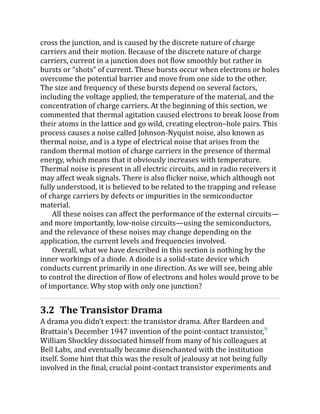
of importance. Why stop with only one junction?
3.2 The Transistor Drama
A drama you didn’t expect: the transistor drama. After Bardeen and
Brattain's December 1947 invention of the point-contact transistor,9
William Shockley dissociated himself from many of his colleagues at
Bell Labs, and eventually became disenchanted with the institution
itself. Some hint that this was the result of jealousy at not being fully
involved in the final, crucial point-contact transistor experiments and
37.
frustration at notprogressing rapidly up the laboratory management
ladder. Mr. Shockley had, in the words of his employees, an unusual
management style.10
Shockley recognized that the point-contact transistor delicate
mechanical configuration would be difficult to manufacture in high
volume with sufficient reliability. He also disagreed with Bardeen's
explanation of how their transistor worked. Shockley claimed that
positively charged holes could also penetrate through the bulk
germanium material, not only trickle along a surface layer. And he was
right. On February 16, 1948, physicist John Shive achieved transistor
action in a sliver of germanium with point contacts on opposite sides,
not next to each other, demonstrating that holes were indeed flowing
through the thickest part of the crystal.
All we have said before about the p–n junction before applies to
transistors. But transistors have three distinctive areas, with two
boundaries or junctions: n–p–n, or p–n–p, typically called emitter, base
and collector. Emitters are heavily doped with impurities, and for that it
is usually called n++ or p++. The base is weakly doped, and for the
collector this is not so important, and its doping depends on the
manufacturing process. The most important constructive factor is the
based width, or W. The junction separating emitter from base is called,
no wonder, emitter junction, whereas the junction separating base from
collector is called—drum roll—collector junction. Naming at least is not
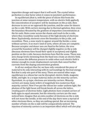
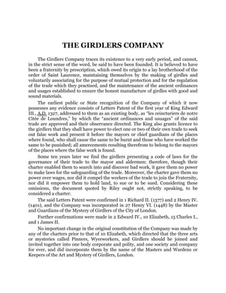
complicated (Fig. 3.2).
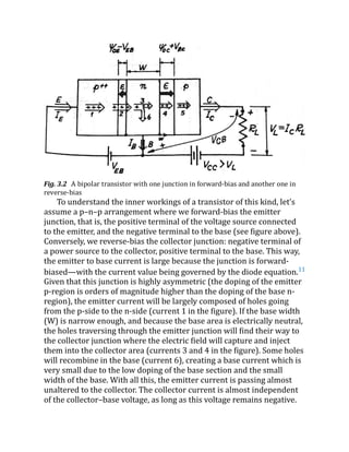
38.
Fig. 3.2 Abipolar transistor with one junction in forward-bias and another one in
reverse-bias
To understand the inner workings of a transistor of this kind, let’s
assume a p–n–p arrangement where we forward-bias the emitter
junction, that is, the positive terminal of the voltage source connected
to the emitter, and the negative terminal to the base (see figure above).
Conversely, we reverse-bias the collector junction: negative terminal of
a power source to the collector, positive terminal to the base. This way,
the emitter to base current is large because the junction is forward-
biased—with the current value being governed by the diode equation.11
Given that this junction is highly asymmetric (the doping of the emitter
p-region is orders of magnitude higher than the doping of the base n-
region), the emitter current will be largely composed of holes going
from the p-side to the n-side (current 1 in the figure). If the base width
(W) is narrow enough, and because the base area is electrically neutral,
the holes traversing through the emitter junction will find their way to
the collector junction where the electric field will capture and inject
them into the collector area (currents 3 and 4 in the figure). Some holes
will recombine in the base (current 6), creating a base current which is
very small due to the low doping of the base section and the small
width of the base. With all this, the emitter current is passing almost
unaltered to the collector. The collector current is almost independent
of the collector–base voltage, as long as this voltage remains negative.
39.
Otherwise, the collectorwould also inject holes into the base, altering
the overall functioning of the device. This is an important mode
(saturation mode) we will talk about.
The electric field at the collector junction injects the holes into the
collector area, and the magnitude of this electric field does not affect
the number of holes arriving to that place. It is the base and the
diffusion that happens there which defines the number of holes that
will make it to the collector. Even zero volts between collector and base
would keep that current flowing.
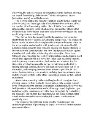
Thus far, we have been analyzing the behavior of the transistor
mostly from its direct-current (DC) biasing perspective. The analysis to
follow should be about observing how the transistor behaves while in
the active region and when fed with small—and not so small—AC
signals superimposed to base voltages, causing the device’s biasing to
fluctuate around certain points, and how the input and output signals
should match each other, minimizing alterations (i.e., distortion).
Although understanding this is of great importance and a topic in itself
which finds applications in a myriad of fields such as analog circuits,
radiofrequency, communications, hi-fi audio, and whatnot, for this
discussion we shall focus on the device in switching mode, that is,
moving between defined, discrete conduction states: from cut-off to
saturation, and swinging between them as fast as possible. In this
mode, the transistor acts as a switch, evolving from one extreme state
(cutoff, or open switch) to the other (saturation, closed switch) as fast
as possible.
A transistor operating in the cutoff region has its two junctions
working in reverse bias mode. In this situation, only leakage current
flows from collector to emitter. Conversely, in saturation, the device has
both junctions in forward-bias mode, allowing a small depletion layer
and allowing the maximum current to flow through it. By controlling
the biasing of the emitter–base junction, we can make the transistor
transition between these two modes; full current conduction or
practically zero.
The transistor in switching mode sets the foundation of the
underlying behavior of practically all digital electronics and computer
systems out there.
40.
So, all thishassle with electrons, holes, donors, acceptors, minority
carriers and gossip at Bell Labs only to create a switch?
Really? Yes.
A very special kind of switch, one that would go down history to
spark a revolution. The junctions we described above, in the form of
diodes and transistors, would become the basic building blocks of our
modern digital toolbox. A toolbox that supports today’s machine
learning, artificial intelligence, cloud computing, but also Instagram,
TikTok and the metaverse. How?
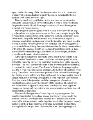
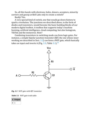
Combining transistors in switching mode can form logic gates. For
instance, a simple bipolar junction transistor (BJT, the one whose inner
working we described in Sect. 3.2) can form a NOT gate, which basically
takes an input and inverts it (Fig. 3.3; Table 3.1).12
Fig. 3.3 NOT gate with BJT transistor
Table 3.1 NOT gate truth table
A Output
0 1
41.
A Output
1 0
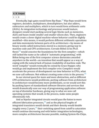
Similarly,a BJT can form a NAND gate (Fig. 3.4; Table 3.2).
Fig. 3.4 NAND gate with BJT transistor
Table 3.2 NAND gate truth table
A B Output
0 0 1
0 1 1
1 0 1
42.
A B Output
11 0
Eventually, logic gates would form flip-flops.13
Flip-flops would form
registers, decoders, multiplexers, demultiplexers, but also adders,
subtractors and multipliers, which in turn would form arithmetic units
(ALUs). As integration technology and processes would mature,
designers would start packing several logic blocks such as memories,
ALUs and buses inside smaller and smaller silicon dies. Then, engineers
would create a clever digital machine whose behavior could be slightly
modified—this means, it would perform different arithmetic operations
and data movements between parts of its architecture—by means of
binary words called instructions stored in a memory, giving way to
machine code and CPU architectures. Corrado Böhm in his Ph.D.
thesis14
would conceive the foundations for the first compiler—which
still lacked the name as he called it “automatic programming”, with
Böhm being one of the first computer science doctorates awarded
anywhere in the world—an invention that would appear as a way of
coping with the natural lack of human readability of machine code. The
word ‘compiler’ would eventually be coined by Grace Hopper, who
would go and implement the first compiler ever. Compilers would
accelerate the process of development run time behavior in CPUs, what
we now call software. Not without creating some crisis in the process.15
In our eternal quest for more and more abstraction, and as different
CPU architectures would proliferate, porting software from architecture
to architecture would become more problematic, so we would sort this
by packing layers of standardized software libraries and services that
would dramatically ease our way of programming application software
on top of dissimilar hardware, giving way to what we now call
operating systems that would, in the process, make some people
obnoxiously rich.
And as bipolar integrated circuits would pass the baton to more
efficient fabrication processes,16
and as the physical lengths of
integrated transistors would shrink and their density would double
roughly every 2 years,17
their switching speed from cutoff to saturation
would continue decreasing and with better integration technologies,
more complex architectures became possible, making System-On-Chips,
43.
CPLDs and laterFPGAs feasible devices and products. Combined with a
new breadth of spectrum-efficient digital modulation and signal
processing techniques, mobile devices would materialize, maturing
with them important related domains and technologies like displays,
allowing us to create arbitrary arrangements of pixels in screens whose
colorful photons would hit our retinas, creating appealing user human–
machine interfaces in applications that would allow us to, for example,
send an emoji to a friend for comedic purposes.
How does space technology relate to all these happenings?
In space, microprocessors and solid-state devices are ubiquitous
because satellites need software, storage, and digital logic in order to
process information on-board and act accordingly. Systems on Chip
(SoCs), FPGAs and logic gates are heavily used. The software and
machine code that spacecraft run on-board to manage their resources,
orientation or to control a payload sensor executes on these types of
devices, and the space environment is not precisely nice with the
microscopic structure that we have just described above. Let’s see
why.18
3.3 The Space Environment
Although we all are technically in space as we travel across interstellar
regions while riding on this geoid we call earth,19
we tend to live in a
sort of crystal bubble in terms of the coziness of this blue dot we live in.
Space is a harsh place to be, at least compared to life here at the surface
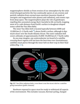
of the ground. We happen to be protected by two huge shields: the
magnetosphere, which captures and deflects particles of different
energies that otherwise would be harmful for us, and by a thick layer of
gas we call atmosphere which captures and neutralizes space debris
wanting to hit us in the head. And both shields complement each other
well.
Unlike Mercury, Venus, and Mars, Earth is surrounded by an
immense magnetic field called the magnetosphere. The Earth has a
magnetic field because it has a molten outer core of iron and nickel that
is constantly in motion. The motion of the liquid outer core creates
electrical currents, which in turn generate a magnetic field, as André-
Marie Ampère stated in his eponymous circuital law. Our
44.
magnetosphere shields usfrom erosion of our atmosphere by the solar
wind (charged particles the Sun continually spews at us), erosion and
particle radiation from coronal mass ejections (massive clouds of
energetic and magnetized solar plasma and radiation), and cosmic rays
from deep space. The magnetosphere plays the role of gatekeeper,
repelling this unwanted energy that’s harmful to life on Earth, trapping
most of it a safe distance from Earth’s surface in doughnut-shaped
zones called the Van Allen Belts.
The inner Van Allen belt is located typically between 6000 and
12,000 km (1–2 Earth radii20
) above Earth’s surface, although it dips
much closer over the South Atlantic Ocean. The outer radiation belt
covers altitudes of approximately 25,000–45,000 km (4–7 Earth radii).
As you may imagine, any semiconductor on-board of a satellite
crossing these regions will not have the best time ever. Geostationary
satellites must pierce through the inner belt on their way to their final
orbits (Fig. 3.5).
Fig. 3.5 Van Allen radiation belts; cross them is not the nicest ride for a satellite
going somewhere (public domain)
Hardware exposed to space must be ready to withstand all aspects
of the environment. This includes vacuum, thermal cycling, charged
John’s, Watling Street,was annexed to it, these being annexed to St. Mary-le-Bow
by Order in Council dated July 21, 1876.
Houseling people in 1548 were 300.
On the south side of the chancel there was a small part of the church, called
“The Salters’ Chapel,” containing a window with the figure of the donor, Thomas
Beaumont, wrought upon it. The church originally had a steeple, but in 1559 it was
destroyed by lightning and not restored. The King granted a licence to Roger Paryt
and Roger Stagenhow to found a guild in honour of our Lord, April 12, 1394 (Pat.
17 Rd. II. p. 2 m. 15). Some of the most notable monuments were those of Thomas
Beaumont of the Company of Salters, John Dunster, a benefactor of the church,
and Arthur Baron.
The following were among the numerous benefactors: David Cocke, £100;
William Parker, £100; John Dunster, £200, to be laid out in lands and tenements;
Edward Rudge, £200, to be laid out in lands and tenements; Lady Middleton,
£100.
The most notable rectors of the church were: William Lyndwood (d. 1446),
Chancellor to the Archbishop of Canterbury; Thomas Langton (d. 1501), Bishop of
St. David’s. John Milton was baptized in this church.
A tablet formerly affixed to the exterior of the church in commemoration of
the event was put up outside St. Mary-le-Bow after the destruction of Allhallows.
Friday Street.—“So called,” says Stow, “of fishmongers
dwelling there, and serving Friday’s market.” In the roll of the Scrope
and Grosvenor controversy, the poet Chaucer is recorded as giving
evidence connected with this street, for when he was once in Friday
Street he observed a sign with the arms of Scrope hanging out; and
on his asking what they did there, was told they were put there by Sir
Robert Grosvenor.
Cunningham also notes as follows: “The Nag’s Head Tavern, at
the Cheapside corner of Friday Street, was the pretended scene of the
consecration of Matthew Parker, Archbishop of Canterbury in the
reign of Queen Elizabeth. The real consecration took place in the
adjoining church of St. Mary-le-Bow; but the Roman Catholics chose
to lay the scene in a tavern. ‘The White Horse,’ another tavern in
Friday Street, makes a conspicuous figure in the Merry Conceited
Jests of George Peele. In this street, in 1695, at the ‘Wednesdays
Clubs,’ as they were called, certain well-known conferences took
place, under the direction of William Paterson, which ultimately led
to the establishment of the Bank of England.”
47.
In the year1247, certain lands in Friday Street are held by the
nuns of “Halliwelle.” In 1258, one William Eswy, mercer, bequeathed
to the Earl of Gloucester all his tenements in Friday Street for 100
marks, wherein he was bound to the Earl, and for robes, capes, and
other goods received from him. In 1278, Walter de Vaus left to
Thomas, his uncle, shops in Friday Street. Therefore in the thirteenth
century the street was already a lane of shops. The date shows that
the former character of Chepe market as a broad open space set with
booths and stalls had already undergone great modifications. Other
early references to the street show that it was one of shops. Chaucer’s
evidence shows that a hundred years later there were “hostelers” or
“herbergeours” living there.
In 1363, certain citizens subscribed money as a present to the
King. Among them is one Thomas, a scrivener of Friday Street, and
in 1370 we find one Adam Lovekyn in possession of a seld which has
been used for time out of mind by foreign tanners. He complains that
they no longer come to him, but keep their wares in hostels and go
about the streets selling them in secret.
In Friday Street at the corner in Watling Street is a railed-in
space, all that remains of an old churchyard, the churchyard of St.
John the Evangelist. This is a piece of ground containing very few
square yards, separated from the street by high iron railings, and
filled with stunted laurel bushes and other evergreens. A hard gravel
walk runs round a circular bed of bushes, and on one side stands a
raised tomb-like erection. On the wall are one or two slabs indicating
the names of those who are buried in the vault below.
The Church of St. John the Evangelist was burnt down in the Great Fire
and not rebuilt, its parish being annexed to Allhallows, Bread Street, and both of
these to St. Mary-le-Bow, by Order in Council, 1876. The earliest date of an
incumbent is 1354.
The patronage of the church was in the hands of: The Prior and Convent of
Christ Church, Canterbury, before 1354; Henry VIII. seized it in 1540; the Dean
and Chapter of Christ Church, Canterbury, 1546 up to 1666, when it was annexed
to Allhallows, Bread Street.
Houseling people in 1548 were 100.
A chantry was founded here by William de Angre, before 1361, whose
endowment fetched £8 : 13 : 4 in 1548, when John Taylor was chaplain. No
monuments of any note are recorded by Stow.
48.
In the northpart of Friday Street is Blue Boar Court on the east
side. This court was rebuilt in 1896, but previous to this was
surrounded by old houses. One of these, No. 56, was interesting as
having been the City home of Richard Cobden until 1845. It is said
that this house was built on the site of a garden attached to Sir Hugh
Myddelton’s house in Cheapside. The cellars beneath the building
once covered the bullion belonging to the Bank of England. This was
at the time when the Bank was in a room of the old Grocers’ Hall.
The Church of St. Matthew, Friday Street, was situated on the west side
of the street near Cheapside. It was burnt down in the Great Fire, and rebuilt from
the designs of Sir Christopher Wren in 1685; it was then made the parish church
for this and St. Peter’s, Westcheap, which was annexed to it. About 1887 the
building was pulled down. The earliest date of an incumbent is 1322.
The patronage of the church was in the hands of: The Abbot and Convent of
St. Peter, Westminster, 1322, then Henry VIII., who seized it and gave it to the
Bishop of Westminster, January 20, 1540-41; the Bishop of London, March 3,
1553-54; it continued in his successors up to 1666, when St. Peter’s, Cheapside, was
annexed, and the patronage was shared alternately with the patron of that parish.
Houseling people in 1548 were 200.
The church was plain, without aisles, measuring 64 feet by 33 feet and having
a tower 74 feet high.
Chantries were founded here: By Adam de Bentley, goldsmith, for himself and
Matilda his wife, to which Adam Ipolite de Pontefracto was admitted chaplain,
June 14, 1334; by Thomas Wyrlyngworth, at the Altar of St. Katherine, to which
John Donyngton was admitted chaplain, November 13, 1391: the King granted his
licence, June 16, 1404; by John Martyn, whose endowment fetched £10 in 1548,
when Henry Coldewell was priest, “70 years of age, meanly learned”; for Nicholas
Twyford, miles, about 1400.
The church originally contained monuments to Sir Nicholas Twyford,
goldsmith and mayor, who died 1583, also Sir Edward Clark, Lord Mayor in 1696.
Sir Hugh Myddelton, the designer of the New River, was a parishioner, and was
buried here in 1631.
A legacy of £5 a year was left to the poor of the parish by Mrs. Cole.
James Smith, Edward Clark, and others contributed to the furnishing of the
necessities of the church. The parish was to receive £240 out of the “cole-money”
for the use of the parish or poor (Stow).
John Thomas (1691-1766), Bishop of Lincoln, 1744, of Sarum 1761-66, was
rector here; also Edward Vaughan (d. 1522), Bishop of St. David’s; John Rogers,
who was burnt at Smithfield, 1555; Lewis Bayley (d. 1631), Bishop of Bangor, and
Michael Lort (1725-90), Vice-President of Society of Antiquaries; Henry Burton,
49.
the ardent Puritan,who was put in the pillory and imprisoned for his religious
opinions and attacks.
The Church of St. Margaret Moses was situated on the east side of Friday
Street, opposite Distaff Lane, now merged in Cannon Street, and derived its name
from one Moses, who founded it. It was burnt down in the Great Fire and its parish
annexed to that of St. Mildred, Bread Street. The earliest date of an incumbent is
1300.
The patronage of the church was in the hands of: Robert Fitzwalter, the
founder, who gave it in 1105 to the Priors and Canons of St. Faith, Horsham,
Norfolk, being confirmed to that house by Pope Alexander III. in his Bill dated at
Turin, May 26, 1163; Edward III., who seized it from St. Faith, as an alien priory,
and so it continued in the Crown till the parish was annexed to St. Mildred, Bread
Street, in 1666.
Houseling people in 1548 were 240.
Chantries were founded here by: Nicholas Bray, whose endowment fetched
£8 : 16 : 8 in 1548, when John Griffyn was “priest of the age of 46 years, of virtuous
living and of small learning”; John Fenne, whose endowment yielded £9 : 10s. in
1548, when John Brightwyse was “priest of the age of 46 years, of honest behaviour
and indifferently learned”; Gerard Dannyell, whose endowment fetched £8 in
1548, when Nicholas Prideoux was priest.
The church originally contained monuments to Sir Richard Dobbes, mayor,
1551; Sir John Allot, mayor, 1591.
Only two legacies are recorded by Stow: 18s. per annum, the gift of John Bush;
16s. per annum, the gift of John Spot.
John Rogers, who was burnt at Smithfield in 1555, was rector here.
Distaff Lane.—“On the west side of Friday Street, is Mayden
lane, so named of such a sign, or Distaffe lane, for Distar lane, as I
read in the record of a brew-house called the Lamb, in Distar Lane,
the 16th of Henry VI. In this Distar Lane, on the north side thereof, is
the Cordwainers, or Shoemakers’ hall, which company were made a
brotherhood or fraternity, in the 11th of Henry IV. Of these
cordwainers I read, that since the fifth of Richard II. (when he took
to wife Anne, daughter to Wenceslaus, King of Bohemia), by her
example, the English people had used piked shoes, tied to their knees
with silken laces, or chains of silver or gilt, wherefore in the 4th of
Edward IV. it was ordained and proclaimed, that beaks of shoone
and boots, should not pass the length of two inches, upon pain of
cursing by the clergy, and by parliament to pay twenty shillings for
50.
every pair. Andevery cordwainer that shod any man or woman on
the Sunday, to pay thirty shillings.
“On the south side of this Distar Lane, is also one other lane,
called Distar Lane, which runneth down to Knightrider Street, or Old
Fish Street, and this is the end of Bread Street Ward” (Stow’s Survey,
p. 393).
The other lane was afterwards called Little Distaff Lane. Another
name for this street was Maiden Lane. There was another Maiden
Lane in Thames Street, and a third in Lad Lane, and a fourth on
Bank side.
Distaff Lane is absorbed by Cannon Street, and the “Little
Distaff Lane” has been promoted by the omission of the adjective.
Old Change.—Of this street Stow tells us everything that is of
interest:
“A street so called of the King’s exchange there kept, which was
for the receipt of bullion to be coined. For Henry III., in the 6th year
of his reign, wrote to the Scabines and men of Ipre, that he and his
council had given prohibition, that none, Englishmen or other,
should make change of plate or other mass of silver, but only in his
Exchange at London, or at Canterbury. Andrew Bukerell then had to
farm the Exchange, and was mayor of London, in the reign of Henry
III. In the 8th of Edward I., Gregory Rockesly was keeper of the said
Exchange for the king. In the 5th of Edward II., William Hausted was
keeper thereof; and in the 18th, Roger de Frowicke.
“These received the old stamps, or coining-irons, from time to
time, as the same were worn, and delivered new to all the mints in
England, as more at large in another place I have noted.
“This street beginneth by West Chepe in the north, and runneth
down south to Knightrider Street; that part thereof which is called
Old Fish Street, but the very housing and office of the Exchange and
coinage was about the midst thereof, south from the east gate that
entereth Pauls churchyard, and on the west side in Baynard’s castle
ward.
“On the east side of this lane, betwixt West Cheape and the
church of St. Augustine, Henry Walles, mayor (by license of Edward
I.), built one row of houses, the profits rising of them to be employed
on London Bridge” (Stow’s Survey, p. 35).
51.
Lord Herbert ofCherbury lived in a “house among gardens near
the Old Exchange.”
St. Paul’s School was founded by Dean Colet in 1509, and the
schoolhouse stood at the east end of the Churchyard, facing the
Cathedral. It was destroyed by the Great Fire and rebuilt by Wren,
and then again taken down and rebuilt in 1824, and subsequently
removed to Hammersmith to the new building designed by Alfred
Waterhouse, R.A., in 1884. For further, see “Hammersmith” in
succeeding volume. The old site in St. Paul’s Churchyard is now
covered by business houses.
53.
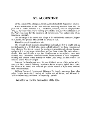
ST. AUGUSTINE
At thecorner of Old Change and Watling Street stands St. Augustine’s Church.
It was burnt down by the Great Fire and rebuilt by Wren in 1682, and the
parish of St. Faith’s annexed to it. The steeple, however, was not completed till
1695. As it possessed no proper burying-ground of its own, a portion of the crypt of
St. Paul’s was used for the interment of parishioners. The earliest date of an
incumbent was 1148.
The patronage of the church was always in the hands of the Dean and Chapter
of St. Paul’s, who granted it to Edward, the priest, in 1148.
Houseling people in 1548 were 360.
The present church measures about 51 feet in length, 30 feet in height, and 45
feet in breadth; it is divided into a nave and side aisles by six Ionic columns and
four pilasters. The steeple rises at the south-west, consisting of a tower, lantern,
and spire. It is 20 feet square at the base, and has three stories. The lantern is very
slender. The total altitude is 140 feet. No chantries are recorded to have been
founded here. The ancient church contained few monuments of note. The present
building has a tablet to the memory of Judith (died 1705), the first wife of the
eminent lawyer William Cowper.
Some of the benefactors were: Thomas Holbech, rector of the parish, 1662,
who gave £100 towards finishing the church; Dame Margaret Ayloff, £100. After
the parish of St. Faith’s was annexed, gifts to the amount of £700 were received
from various sources.
William Fleetwood (1656-1723), Bishop of St. Asaph, was rector here; also
John Douglas (1721-1807), Bishop of Carlisle and of Sarum, and Richard H.
Barham (1788-1845), author of The Ingoldsby Legends.
With this we end the first section of the City.
54.
GROUP II
The secondgroup of streets will be those lying north of Gresham
Street, with Noble Street and Monkwell Street on the west, and
Moorgate Street on the east. This part of the City is perhaps less rich
in antiquities and associations than any other. The north part was, to
begin with, occupied and built over with houses much later than the
south. For a long time the whole area north of Gresham (then
Cateaton) Street and within the Wall presented the appearance of
gardens and orchards with industrial villages as colonies dotted here
and there, each with its parish church and its narrow lane of
communication with the great market of Chepe. Some of the names,
as Oat Lane, Lilypot Lane, Love Lane, preserve the memory of the
gardens and their walks.
In this district grew up by degrees a great many of the industries
of the City, especially the noisy trades and those which caused
annoyance to the neighbours, as that of the foundry, the tanyard, the
tallow chandlers.
An examination of the Calendar of Wills down to the fifteenth
century is in one sense disappointing, because it affords no insight
into the nature of the trades carried on in the area before us. On the
other hand, it curiously corroborates the theory that this part of the
City was in the thirteenth and fourteenth centuries purely industrial,
because among the many entries referring to this quarter there is but
one reference, down to the seventeenth century, of any shops. There
are rents, tenements—“all my Rents and Tenements” several times
repeated; land and rents—“all my Land and Rents”; there are
almshouses, Halls of Companies, gardens; but there are no shops,
and that at a time when the streets and lanes about Cheapside are
filled with shops!
55.
The Companies’ Hallsoffer some index to the trades of the
quarter. There are still Broderers’ Hall, Curriers’ Hall, Armourers’
Hall, Coopers’ Hall, Parish Clerk’s Hall, Brewers’ Hall, Girdlers’ Hall;
and there were Haberdashers’ Hall, Mercers’ Hall, Wax Chandlers’
Hall, Masons’ Hall, Plaisterers’ Hall, Pinners’ Hall, Barber Surgeons’
Hall, Founders’ Hall, Weavers’ Hall, and Scriveners’ Hall, which have
now been removed elsewhere or destroyed. These trades, we may
note, are for the most part of the humbler kind.
Coleman Street is described by Stow as “a fair and large Street
on both sides built with divers fair houses, besides alleys with small
tenements in great numbers.”
Cunningham enumerates the chief events connected with the
street:
“The five members accused of treason by Charles I. concealed
themselves in this street. ‘The Star,’ in Coleman Street, was a tavern
where Oliver Cromwell and several of his party occasionally met.... In
a conventicle in ‘Swan Alley,’ on the east side of this street, Venner, a
wine-cooper and Millenarian, preached the opinions of his sect to
‘the soldiers of King Jesus’” (see London in the Time of the Stuarts,
p. 68 et seq.). “John Goodwin, minister in Coleman Street, waited on
Charles I. the day before the King’s execution, tendered his services,
and offered to pray for him. The King thanked him, but said he had
chosen Dr. Juxon, whom he knew. Vicars wrote an attack on
Goodwin, called ‘The Coleman-street Conclave Visited!’ Justice
Clement, in Ben Jonson’s Every Man in his Humour, lived in
Coleman Street; and Cowley wrote a play called Cutter of Coleman-
street. Bloomfield, author of ‘The Farmer’s Boy,’ followed his original
calling of a shoemaker at No. 14 Great Bell-yard in this street.”
57.
ST. STEPHEN, COLEMANSTREET
The Church of St. Stephen, Coleman Street, was “at first a Jews’ synagogue,
then a parish church, then a chapel to St. Olave’s in the Jewry, now (7 Edward IV.)
incorporated as a parish church” (Stow). It is situated on the west side of Coleman
Street, near to the south end. It was consumed by the Great Fire and rebuilt by
Wren. The earliest date of an incumbent is 1311.
The patronage of the church was in the hands of: The Dean and Chapter of St.
Paul’s, who granted it to the Prior and Convent of Butley; Henry VIII. seized it, and
in the Crown it continued till Queen Elizabeth granted it, about 1597, to the
parishioners, in whose successors it continued.
Houseling people in 1548 were 880.
The church is plain, long and narrow, without any aisles, measuring 75 feet in
length and 35 feet in breadth. The steeple, which rises at the north-west, consists
of a stone tower, a lantern, and small spire, the total height being about 65 feet.
Chantries were founded here by: William Grapefig, for which the King granted
a licence, August 6, 1321, and to which John de Maderfield was admitted chaplain,
June 23, 1324; Rodger le Bourser, for which the King granted his licence, August 1,
1321; Stephen Fraunford and John Essex, both citizens of London, of which John
de Bulklegh was chaplain, who died in 1391: founded July 1361; Edward IV., who
endowed it with lands, etc., which fetched £50 : 5 : 4 in 1548.
Anthony Munday, the dramatist, arranger of the City pageants and the
continuation of Stow’s Survey, who died in 1633, was buried here.
A very large number of legacies and charitable gifts are recorded by Stow,
amongst which are: £640, the gift of Christopher Eyre, for the building and
maintenance of six almshouses; £100, the gift of Sir Richard Smith, for coals for
the poor; £100, the gift of Hugh Capp, for lands for the poor; £400, the gift of
Barnard Hyde, to purchase land for six poor people for ever.
In White Alley there were six almshouses built by Christopher Eyre for six
poor couples, each of whom were allowed £4 per annum.
Richard Lucas (1648-1715), author of several theological works, was a rector
here; also John Davenport (1597-1670), he was one of the leaders of a party who
went over to America in 1637, and founded Newhaven in Connecticut. He had a
design of founding a university (Yale), but this was not carried into effect until
sixty years later.
Over the stuccoed gateway of the churchyard is a skull and cross-bones, with
an elaborate panel in relief below, representing the Last Judgment; this is a replica
in oak of the original panel, which was removed, for its better preservation, to the
Vestry.
58.
As for thepresent street the most notable building is the
Armourers’ Hall.
60.
THE ARMOURERS ANDBRASIERS
COMPANY
The trade of armourer was of great importance in the ages when men went out
to war clad in iron. There were many kinds of armour. Some were taught to make
helmets and some corslets. There was armour of quilted leather worn under the
armour or acting as armour.
T. H. Shepherd.
THE ARMOURERS’ AND
BRASIERS’ ALMSHOUSES,
BISHOPSGATE WITHOUT
(1857)
A great number of people lived by the making of armour. The custom of
wearing armour decayed gradually, not rapidly. It is still kept up for purposes of
show but no longer for any use in defence.
The origin of the Company of Armourers and Brasiers is lost in antiquity. The
Company was, however, founded previously to the beginning of the fourteenth
century, for records are in existence showing that at that time (1307-27) the
Company had vested in it the right of search of armour and weapons. It would
61.
appear from documentsin the possession of the Company that as early as the year
1428 the Company was in the possession of a hall. In the year 1453 the Company
was incorporated by a charter from King Henry VI. by the title of “The Fraternity
or Guild of St. George of the Men of Mistery of Armorers of our City of London,”
and had licence granted to it to appoint a chaplain to its chapel in St. Paul’s
Cathedral.
It is believed that the Company of Brasiers was incorporated about the year
1479 by Edward IV., and that the craft of bladesmiths was incorporated with the
Company of Armourers about the year 1515, but the Company has no authentic
evidence in its possession as to these facts.
In the year 1559, Queen Elizabeth granted a charter of Inspeximus, confirming
the Letters Patent of King Henry VI.
In the year 1618, King James I., in consideration of the sum of £100, granted
Letters Patent confirming the title of the Fraternity or Guild of St. George of the
Men of Mystery of Armourers in the City of London, to the messuages and lands
then held by it. The greater part of these messuages and lands is still in the
possession of the Company.
In the year 1685, King James II. granted Letters Patent to the Company which
(inter alia) directed that all edge tools and armour, and all copper and brass work
wrought with the hammer within the City of London, or a radius of five miles
therefrom, should be searched and approved by expert artificers of the Company.
In the year 1708 the Company of Armourers was, by Letters Patent granted by
Queen Anne, incorporated with the Brasiers under the corporate title of “The
Company of Armourers and Brasiers in the City of London.” In this charter it is
recited that of late years many of the members of the Company of Armourers had
employed themselves in working and making vessels, and wares of copper and
brass wrought with the hammer, and that for want of powers to search and make
byelaws to bind the workers of such wares in the City of London, frauds and deceits
in the working of such goods and vessels had increased, and power was thereby
granted to the Company of Armourers and Brasiers to make byelaws for the
government of the Company; and also of all persons making any work or vessel of
wrought or hammered brass or copper, in the Cities of London and Westminster,
or within a radius of five miles thereof, and with authority to inflict fines and
penalties against persons offending against such byelaws. And the Company was
invested with power to inspect and search for all goods worked or wrought with the
hammer and exposed to sale within such limits as aforesaid. No person was
allowed to sell or make armour or vessels, or wares of copper or brass wrought
with the hammer, unless he was a member or had been apprenticed to a member
of the Company.
It would appear that the master and wardens exercised a very extensive
jurisdiction in ancient days, fining and punishing members of the Company for
social offences as well as for infringements of the byelaws of the Company, and
hearing and adjudicating upon all questions arising between members of the
62.
Company and theirapprentices, and also inflicting fines on persons making or
selling goods of an improper quality.
This Company is still in the habit of binding apprentices to masters engaged in
the trades of workers of brass and copper, and of pensioning infirm members of
those trades. Their workshops were situated close to London Wall, below
Bishopsgate, probably in order to remove their hammering as far as possible from
the trading part of the City.
The Company is governed by a Master, an Upper Warden and a Renter
Warden, with eighteen assistants, and, together with the livery, now number 91.
The Hall is at 81 Coleman Street. Stow mentions the Hall on the north end of
Coleman Street and on the east side of it. “The Company of Armourers were made
a Fraternity or Guild of St. George with a Chantry in the Chapel of St. Thomas in
Paul’s Church in the 1st of Henry VI.”
On the north side of King’s Arms Yard extends the elaborate and
very handsome building of the Metropolitan Life Assurance Society,
which has its entrance at the corner of Moorgate Street. This has
deeply recessed windows, and the corner is finished off by an
octagonal turret which begins in a projecting canopy over the door,
and is carried up to the roof. In niches here and there are small stone
figures. This building is the work of Aston Webb and Ingress Bell in
1891. Opposite, in great contrast, are oldish brick houses, very plain
in style. Round the northern corner into Coleman Street is carried a
building which is chiefly remarkable for the amount of polished
granite on its surface. On the west, a little higher up, is another
entrance of the Wool Exchange from which a large projection
overhangs the street. There is a lamb in stonework over the door.
Basinghall Street (or Bassishaw Street) runs from London
Wall to Gresham Street. The street used to contain the Masons’,
Weavers’, Coopers’, and Girdlers’ Halls. Only the Girdlers’ and
Coopers’ Halls now remain. The names Basinghall and Bassishaw are
frequently supposed to have the same origin. Riley, however, quotes
a passage in which (A.D. 1390) there is mention of the “Parish of St.
Michael Bassishaw in the Ward of Bassyngeshaw,” which he
considers indicates that the word Basseshaw is Basset’s haw, and
Bassyngeshaw is Basing’s haw, referring to two families and not one.
There is a great number of references to Basings and to Bassets. Yet
the names seem to refer to the same place. Thus in 1280 and 1283 we
hear of houses in Bassieshaw. In 1286 we hear of houses in Bassinge
haw. Basinghall was the hall or house of the Basings, an opulent
63.
family of thethirteenth century. Solomon and Hugh Basing were
sheriffs in 1214; Solomon was mayor in 1216; Adam Basing was
sheriff in 1243. Basinghall passed into the hands of a family named
Banquelle or Bacquelle. John de Banquelle, Alderman of Dowgate,
had a confirmation and quit claim to him of a messuage in St.
Michael, Bassieshawe, in 1293.
At the south-west corner of Basinghall Street was a fine stone
house built by a “certain Jew named Manscre, the son of Aaron.”
Thomas Bradberry (d. 1509) kept his mayoralty there.
65.
THE GIRDLERS COMPANY
TheGirdlers Company traces its existence to a very early period, and cannot,
in the strict sense of the word, be said to have been founded. It is believed to have
been a fraternity by prescription, which owed its origin to a lay brotherhood of the
order of Saint Laurence, maintaining themselves by the making of girdles and
voluntarily associating for the purpose of mutual protection and for the regulation
of the trade which they practised, and the maintenance of the ancient ordinances
and usages established to ensure the honest manufacture of girdles with good and
sound materials.
The earliest public or State recognition of the Company of which it now
possesses any evidence consists of Letters Patent of the first year of King Edward
III., A.D. 1327, addressed to them as an existing body, as “les ceincturiers de notre
Citée de Loundres,” by which the “ancient ordinances and usuages” of the said
trade are approved and their observance directed. The King also grants licence to
the girdlers that they shall have power to elect one or two of their own trade to seek
out false work and present it before the mayors or chief guardians of the places
where found, who shall cause the same to be burnt and those who have worked the
same to be punished; all amercements resulting therefrom to belong to the mayors
of the places where the false work is found.
Some ten years later we find the girdlers presenting a code of laws for the
governance of their trade to the mayor and aldermen; therefore, though their
charter enabled them to search into and discover bad work, it gave them no power
to make laws for the safeguarding of the trade. Moreover, the charter gave them no
power over wages, nor did it compel the workers of the trade to join the Fraternity,
nor did it empower them to hold land, to sue or to be sued. Considering these
omissions, the document quoted by Riley ought not, strictly speaking, to be
considered a charter.
The said Letters Patent were confirmed in 1 Richard II. (1377) and 2 Henry IV.
(1401), and the Company was incorporated in 27 Henry VI. (1448) by the Master
and Guardians of the Mystery of Girdlers of the City of London.
Further confirmations were made in 2 Edward IV., 10 Elizabeth, 15 Charles I.,
and 1 James II.
No important change in the original constitution of the Company was made by
any of the charters prior to that of 10 Elizabeth, which directed that the three arts
or mysteries called Pinners, Wyerworkers, and Girdlers should be joined and
invited together into one body corporate and polity, and one society and company
for ever, and did incorporate them by the name of the Masters and Wardens or
Keepers of the Art and Mystery of Girdlers, London.
66.
It does notappear that the Pinners and Wyerworkers brought any accession of
property to the Girdlers.
The Hall has always been in Basinghall Street. Here it is mentioned by Stow
along with Masons’ Hall and Weavers’ Hall.
No. 1 on the east of Basinghall Street was probably built early in
the nineteenth century; the buildings which follow it are chiefly
modern. The whole street is rather fine, though too narrow for much
effect. There are in it many great “houses,” “chambers,” and
“buildings” occupied in floors. Gresham Buildings are faced with
dark-coloured stone and rise comparatively high. The ground-floor
walls on the exterior are covered with the most elaborate stonework
representations of flowers and foliage. The City of London Court in
the passage known as Guildhall Buildings is picturesquely built in a
perpendicular style of Gothic. A great square stone building opposite
was built in 1890, and next to it a plain Portland stone edifice
contains the Lord Mayor’s court office. The City Library and Museum
form a picturesque group of buildings in the west of Basinghall
Street.
Near at hand is the Coopers’ Hall with a narrow frontage.