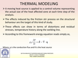
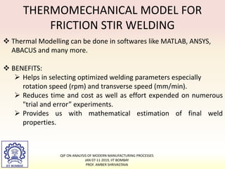
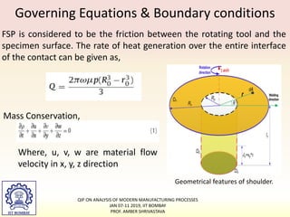
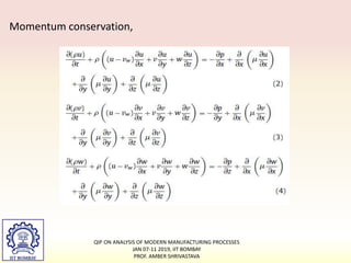
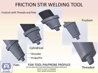
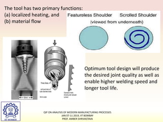
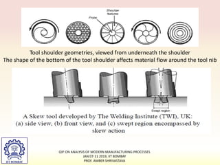
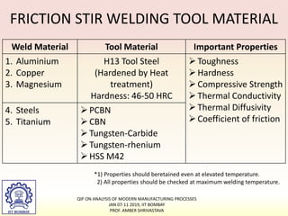
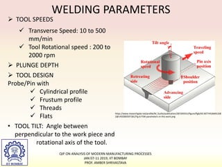
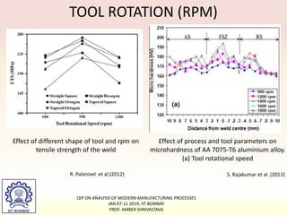
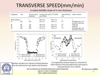
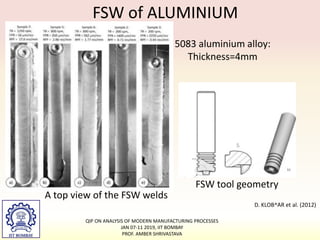
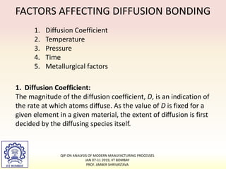
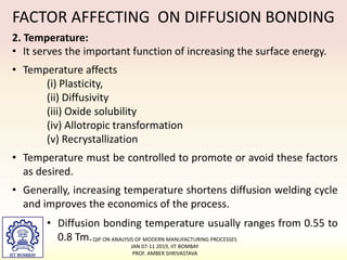
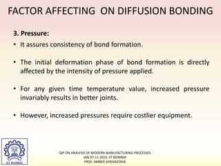
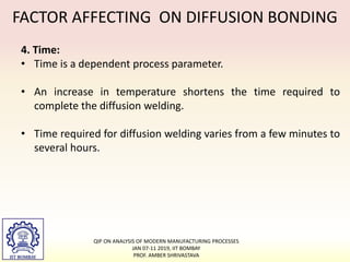
SOLID STATE JOINING
QIP ON ANALYSIS OF MODERN MANUFACTURING PROCESSES
JAN 07-11 2019, IIT BOMBAY
PROF. AMBER SHRIVASTAVA
1
Introduction
• A joining process which creates the joint without melting the
workpiece is known as solid state joining process. Such
processes can also be defined as the joining processes during
which the workpiece temperature never crosses its liquidus
temperature.
• There are different mechanisms of solid state joining
processes:
– Deformation based joining processes
– Diffusion based joining processes
– Adhesion based joining processes, etc.
QIP ON ANALYSIS OF MODERN MANUFACTURING PROCESSES
JAN 07-11 2019, IIT BOMBAY
PROF. AMBER SHRIVASTAVA
Deformation based Joining Processes
Under sufficiently high stresses or combination of high temperature
and high stresses, metals deform: change in shape or size
(accompanied with change in microstructure). When two workpieces
are deformed together such that a perfect contact established
between the workpieces, it could lead to the joint formation. Some of
the deformation based joining processes are:
• Cold/pressure welding
• Roll Bonding
• Friction welding
• Friction stir welding
• Ultrasonic welding
• Explosive welding
QIP ON ANALYSIS OF MODERN MANUFACTURING PROCESSES
JAN 07-11 2019, IIT BOMBAY
PROF. AMBER SHRIVASTAVA
3
Friction Stir Welding
QIP ON ANALYSIS OF MODERN MANUFACTURING PROCESSES
JAN 07-11 2019, IIT BOMBAY
PROF. AMBER SHRIVASTAVA
4
Friction stir welding (FSW) was
developed by TWI, Inc. in 1991.
Solid state welding process.
Non-consumable tool rotates and
plunges into workpiece.
Heat is generated by friction and heat
dissipation due to plastic deformation.
The plasticized material is mixed and
extruded past the tool after which it is
forged together in the wake of the tool.
QIP ON ANALYSIS OF MODERN MANUFACTURING PROCESSES
JAN 07-11 2019, IIT BOMBAY
PROF. AMBER SHRIVASTAVA
5
PRINCIPLE OF FSW
 Rotating tool is plunged into the workpiece.
 Heat generation sources: friction & plastic deformation.
 After the softening of metal below melting point, tool travels.
 On cooling, a solid phase weld is created.
QIP ON ANALYSIS OF MODERN MANUFACTURING PROCESSES
JAN 07-11 2019, IIT BOMBAY
PROF. AMBER SHRIVASTAVA
6
STAGES OF FSW PROCESS
INTRODUCTION: Demonstration
QIP ON ANALYSIS OF MODERN MANUFACTURING PROCESSES
JAN 07-11 2019, IIT BOMBAY
PROF. AMBER SHRIVASTAVA
Heat source
Characteristics:
• Heat source should release the heat in a sharply defined
isolated zone.
• Heat should be produced at a high temperature and high rate.
Source:
• The electric arc (as in various arc welding).
• The chemical flame (as in gas welding).
• Exothermal chemical reactions (as in thermite welding).
• An electric resistance heating (as in electroslag and other
resistance welding).
QIP ON ANALYSIS OF MODERN MANUFACTURING PROCESSES
JAN 07-11 2019, IIT BOMBAY
PROF. AMBER SHRIVASTAVA
8
ADVANTAGES / DISADVANTAGES
 Advantages:
 Dissimilar material joining.
 No fumes, filler material,
Shielding Gas
 Butt, Lap, Spot Weld
geometries.
 Excellent Mechanical
Properties.
 No ultra-violent and or
electromagnetic radiation.
 Disadvantages:
 No fillet welds.
 No complex weld shapes.
 Presence of exit hole.
 Relatively complex
clamping of workpieces.
 More power consumption.
QIP ON ANALYSIS OF MODERN MANUFACTURING PROCESSES
JAN 07-11 2019, IIT BOMBAY
PROF. AMBER SHRIVASTAVA
APPLICATIONS
 Applications: Marine, Aerospace, Transportation industry, etc.
NASA’s Orion Spacecraft
Super Liner Ogasawara
High Speed Railway Carriages
http://www.holroyd.com/blog/friction-stir-welding-applications/
QIP ON ANALYSIS OF MODERN MANUFACTURING PROCESSES
JAN 07-11 2019, IIT BOMBAY
PROF. AMBER SHRIVASTAVA
EQUIPMENT
ROBOTIC FSW CNC MILLING MACHINE
FRICTION STIR WELDING MACHINE
QIP ON ANALYSIS OF MODERN MANUFACTURING PROCESSES
JAN 07-11 2019, IIT BOMBAY
PROF. AMBER SHRIVASTAVA
JOINT DESIGN
QIP ON ANALYSIS OF MODERN MANUFACTURING PROCESSES
JAN 07-11 2019, IIT BOMBAY
PROF. AMBER SHRIVASTAVA
THERMAL MODELING
A moving heat source is applied to a control volume representing
the actual size of the heat affected zone at each time step of the
analysis.
The effects induced by the friction stir process on the structural
behaviour are the target of this kind of study.
These effects can show in terms of distortions and residual
stresses, temperature history along the welding line.
According to this framework energy equation reads simply as,
Where, q is the conduction flux and R is the heat source
QIP ON ANALYSIS OF MODERN MANUFACTURING PROCESSES
JAN 07-11 2019, IIT BOMBAY
PROF. AMBER SHRIVASTAVA
THERMOMECHANICAL MODEL FOR
FRICTION STIR WELDING
 Thermal Modelling can be done in softwares like MATLAB, ANSYS,
ABACUS and many more.
 BENEFITS:
 Helps in selecting optimized welding parameters especially
rotation speed (rpm) and transverse speed (mm/min).
 Reduces time and cost as well as effort expended on numerous
"trial and error” experiments.
 Provides us with mathematical estimation of final weld
properties.
QIP ON ANALYSIS OF MODERN MANUFACTURING PROCESSES
JAN 07-11 2019, IIT BOMBAY
PROF. AMBER SHRIVASTAVA
Governing Equations & Boundary conditions
FSP is considered to be the friction between the rotating tool and the
specimen surface. The rate of heat generation over the entire interface
of the contact can be given as,
Geometrical features of shoulder.
Mass Conservation,
Where, u, v, w are material flow
velocity in x, y, z direction
QIP ON ANALYSIS OF MODERN MANUFACTURING PROCESSES
JAN 07-11 2019, IIT BOMBAY
PROF. AMBER SHRIVASTAVA
Momentum conservation,
QIP ON ANALYSIS OF MODERN MANUFACTURING PROCESSES
JAN 07-11 2019, IIT BOMBAY
PROF. AMBER SHRIVASTAVA
Sv is the viscous dissipation heat generation due to plastic material flow
originated by high strain rate inside the shear zone of the workpiece
near the tool and it is given as,
Energy Equation,
Φ is given as,
QIP ON ANALYSIS OF MODERN MANUFACTURING PROCESSES
JAN 07-11 2019, IIT BOMBAY
PROF. AMBER SHRIVASTAVA
Boundary conditions
Heat generation due to plastic work at shoulder workpiece interface
represented as q(r) which is a first boundary condition and given as,
The boundary condition for heat exchange between the top surface of
the workpiece and the surroundings,
At the bottom surface, convective boundary condition can be used for
simplifying the case and avoiding the effect of backing plate,
QIP ON ANALYSIS OF MODERN MANUFACTURING PROCESSES
JAN 07-11 2019, IIT BOMBAY
PROF. AMBER SHRIVASTAVA
CFD BASED FSW MODELING
The governing equations with the boundary conditions are solved by
employing finite volume method in commercial CFD codes like FLUENT.
The predicted temperature distribution at the transverse cross-section during the dwell and
welding stages (A) 37.9 s, (B) 45.0 s, (C) 50.1 s, (E) 60.0 s.
 More heat is generated at the AS during the welding stage because
the relative velocity and shear strain rate at AS is higher than that at
Retreating Side(RS). Shi, L. et al.(2017)
QIP ON ANALYSIS OF MODERN MANUFACTURING PROCESSES
JAN 07-11 2019, IIT BOMBAY
PROF. AMBER SHRIVASTAVA
MATERIAL MOVEMENT
• Material is more consolidated
with increasing the axial force.
• Material movement is divided
into two regions:
1. Shoulder driven region
2. Pin driven region
EFFECT OF FORCE
K. Kumar et al. (2008)
QIP ON ANALYSIS OF MODERN MANUFACTURING PROCESSES
JAN 07-11 2019, IIT BOMBAY
PROF. AMBER SHRIVASTAVA
FEM simulation of FSW
Relation of BSZ distance with speed and welding
velocity
K. N. Krishnan et al. (2002)
QIP ON ANALYSIS OF MODERN MANUFACTURING PROCESSES
JAN 07-11 2019, IIT BOMBAY
PROF. AMBER SHRIVASTAVA
 Contrast difference of BSZ is because of material deformation.
 In NBSZ zone, Mesh is undistorted. So because of less
deformation no banded structure is observed.
 Banded structure distance depends on welding velocity and tool
revolution speed.
 Banded structure distance is same as feed per revolution.
BANDED STRUCTURE ZONE
Optical Image of Banded SZ and Non Banded SZ
A. Tongne et al.(2017)
QIP ON ANALYSIS OF MODERN MANUFACTURING PROCESSES
JAN 07-11 2019, IIT BOMBAY
PROF. AMBER SHRIVASTAVA
Material movement in threaded tool
1. Circumference movement around the tool
2. Vertical movement along the axis.
FSW with threaded tools result in following material movement:
Optical image of Stir zone
M. Guerra et al.(2002)
C. Hamilton et al.(2008)
QIP ON ANALYSIS OF MODERN MANUFACTURING PROCESSES
JAN 07-11 2019, IIT BOMBAY
PROF. AMBER SHRIVASTAVA
• Al 6061 and
copper,
• No offset from
weld line
• Intercalated
microstructure
formed in stir
zone because of
movement of
material.
• Aluminium 1060 and pure
copper
• Tool on aluminium side
• Copper particle
embedded in aluminium
L. E. Murr et al.(1998)
P. Xue et al.(2010)
QIP ON ANALYSIS OF MODERN MANUFACTURING PROCESSES
JAN 07-11 2019, IIT BOMBAY
PROF. AMBER SHRIVASTAVA
FRICTION STIR WELDING TOOL
FSW TOOL PIN/PROBE PROFILES
Shoulder
Probe/Pin
Cylindrical
Frustum
Threaded
Flats
Frustum with Threads and Flats
QIP ON ANALYSIS OF MODERN MANUFACTURING PROCESSES
JAN 07-11 2019, IIT BOMBAY
PROF. AMBER SHRIVASTAVA
The tool has two primary functions:
(a) localized heating, and
(b) material flow
Optimum tool design will produce
the desired joint quality as well as
enable higher welding speed and
longer tool life.
QIP ON ANALYSIS OF MODERN MANUFACTURING PROCESSES
JAN 07-11 2019, IIT BOMBAY
PROF. AMBER SHRIVASTAVA
Tool shoulder geometries, viewed from underneath the shoulder
The shape of the bottom of the tool shoulder affects material flow around the tool nib
QIP ON ANALYSIS OF MODERN MANUFACTURING PROCESSES
JAN 07-11 2019, IIT BOMBAY
PROF. AMBER SHRIVASTAVA
FRICTION STIR WELDING TOOL MATERIAL
Weld Material Tool Material Important Properties
1. Aluminium
2. Copper
3. Magnesium
H13 Tool Steel
(Hardened by Heat
treatment)
Hardness: 46-50 HRC
Toughness
Hardness
Compressive Strength
Thermal Conductivity
Thermal Diffusivity
Coefficient of friction
4. Steels
5. Titanium
PCBN
CBN
Tungsten-Carbide
Tungsten-rhenium
HSS M42
*1) Properties should beretained even at elevated temperature.
2) All properties should be checked at maximum welding temperature.
QIP ON ANALYSIS OF MODERN MANUFACTURING PROCESSES
JAN 07-11 2019, IIT BOMBAY
PROF. AMBER SHRIVASTAVA
WELDING PARAMETERS
 TOOL SPEEDS
 Transverse Speed: 10 to 500
mm/min
 Tool Rotational speed : 200 to
2000 rpm
 PLUNGE DEPTH
 TOOL DESIGN
Probe/Pin with
 Cylindrical profile
 Frustum profile
 Threads
 Flats
• TOOL TILT: Angle between
perpendicular to the work piece and
rotational axis of the tool.
https://www.researchgate.net/profile/M_Guillo/publication/287205551/figure/fig6/AS:30774526691328
2@1450383597181/Fig-6-FSW-parameters-in-this-work.png
QIP ON ANALYSIS OF MODERN MANUFACTURING PROCESSES
JAN 07-11 2019, IIT BOMBAY
PROF. AMBER SHRIVASTAVA
Effect of different shape of tool and rpm on
tensile strength of the weld
Effect of process and tool parameters on
microhardness of AA 7075-T6 aluminium alloy.
(a) Tool rotational speed
S. Rajakumar et al. (2011)
R. Palanivel et al.(2012)
TOOL ROTATION (RPM)
QIP ON ANALYSIS OF MODERN MANUFACTURING PROCESSES
JAN 07-11 2019, IIT BOMBAY
PROF. AMBER SHRIVASTAVA
QIP ON ANALYSIS OF MODERN MANUFACTURING PROCESSES
JAN 07-11 2019, IIT BOMBAY
PROF. AMBER SHRIVASTAVA
31
TRANSVERSE SPEED(mm/min)
M. Peel et al. (2003)
A rolled AA5083 sheet of 3 mm thickness
5083 aluminium alloy:
Thickness=4mm
FSW of ALUMINIUM
FSW tool geometry
A top view of the FSW welds
D. KLOB^AR et al. (2012)
QIP ON ANALYSIS OF MODERN MANUFACTURING PROCESSES
JAN 07-11 2019, IIT BOMBAY
PROF. AMBER SHRIVASTAVA
FSW of COPPER
Cross-section macrographs of FSW copper
joints: (a) 800 rpm, (b) 600 rpm, (c) 400 rpm
(the advancing side is on the right).
Mechanical properties of the parent metal and
FSW copper samples.
G. M. Xie et al. (2007)
Commercial pure copper plate, 5 mm thick
QIP ON ANALYSIS OF MODERN MANUFACTURING PROCESSES
JAN 07-11 2019, IIT BOMBAY
PROF. AMBER SHRIVASTAVA
FSW of MAGNESIUM
Tensile strength of friction stir weld
Micro-hardness distribution in the
same rotation speed of 1500 rpm.
W. Xunhong et al. (2006)
AZ31 magnesium alloy: 4mm thick
QIP ON ANALYSIS OF MODERN MANUFACTURING PROCESSES
JAN 07-11 2019, IIT BOMBAY
PROF. AMBER SHRIVASTAVA
FSW of STEEL
Transverse tensile properties of the weld
Hardness profile across the stir zone in the
weld.
Y.S. Sato et al. (2005)
SAF 2507 (UNS 2750) super duplex stainless steel, 4mm in thickness.
QIP ON ANALYSIS OF MODERN MANUFACTURING PROCESSES
JAN 07-11 2019, IIT BOMBAY
PROF. AMBER SHRIVASTAVA
FSW of TITANIUM
3 mm thick Ti–6Al–4V titanium alloy sheets
Micro-hardness profiles at 1.5 mm
form the bottom of the joints.
Tensile tests results in terms of
percentage with respect to the
parent material UTS
L. Fratini et al (2010)
QIP ON ANALYSIS OF MODERN MANUFACTURING PROCESSES
JAN 07-11 2019, IIT BOMBAY
PROF. AMBER SHRIVASTAVA
FSW OF DISSIMILAR MATERIALS
Image of the Al 7075-steel interface under transverse speed of 100mm/min and tool rotation
speed: a) 600rpm b) 700 rpm, and c) 800rpm
T. Tanaka et al. (2009)
QIP ON ANALYSIS OF MODERN MANUFACTURING PROCESSES
JAN 07-11 2019, IIT BOMBAY
PROF. AMBER SHRIVASTAVA
SEM images showing particles in the
weld nugget:
• Red circles are some
representative IMC particles
• blue ones correspond to steel
fragments encompassed by IMC
layer
Shuhuai Lan et al.(2015)
SEM images of Al-Fe interface in the
advancing side under rotational speed of
1200 rpm and tool offset of 1.63 mm: a
30 mm/min, b 60 mm/min, and c 90
mm/min
QIP ON ANALYSIS OF MODERN MANUFACTURING PROCESSES
JAN 07-11 2019, IIT BOMBAY
PROF. AMBER SHRIVASTAVA
FRICTION STIR WELDING ZONES
https://www.phase-trans.msm.cam.ac.uk/2003/FSW/aaa.html
SN= Stir Nugget BM= Base Metal
TMAZ= Thermo-mechanically Affected Zone RS= Retracting Side
HAZ= Heat Affected Zone AS= Advancing Side
Cross Sectional view of Friction Stir Welded Cast Aluminium Alloy
QIP ON ANALYSIS OF MODERN MANUFACTURING PROCESSES
JAN 07-11 2019, IIT BOMBAY
PROF. AMBER SHRIVASTAVA
Regions of the Processed Zone
QIP ON ANALYSIS OF MODERN MANUFACTURING PROCESSES
JAN 07-11 2019, IIT BOMBAY
PROF. AMBER SHRIVASTAVA
Diffusion based Joining Process:
Diffusion Bonding
QIP ON ANALYSIS OF MODERN MANUFACTURING PROCESSES
JAN 07-11 2019, IIT BOMBAY
PROF. AMBER SHRIVASTAVA
41
• A solid-state welding process that
produces coalescence of the faying
surfaces by the application of
pressure at elevated temperature.
• The process does not involve
macroscopic deformation, or
relative motion of the work pieces.
• A solid filler metal may or may not
be inserted between the faying
surfaces.
Schematic representation of diffusion bonding
using electrical resistance for heating
Work pieces
A
B
Force
DEFINITION OF DIFFUSION BONDING
QIP ON ANALYSIS OF MODERN MANUFACTURING PROCESSES
JAN 07-11 2019, IIT BOMBAY
PROF. AMBER SHRIVASTAVA
DIFFUSION BONDING: CONCEPT
a
b
c
d
e
a) Initial 'point' contact
b) Yielding and creep leading to reduced voids
c) Final yielding and creep (some voids left)
d) Continued vacancy diffusion, leaving few
small voids
e) Bonding is complete
QIP ON ANALYSIS OF MODERN MANUFACTURING PROCESSES
JAN 07-11 2019, IIT BOMBAY
PROF. AMBER SHRIVASTAVA
• 1st stage
– Deformation leading to
interfacial boundary.
• 2nd stage
– Grain boundary migration
and pore elimination.
• 3rd stage
– Volume diffusion and pore
elimination.
asperities come
into contact.
2nd stage: grain
boundary migration
and pore elimination
1st stage: deformation
and interfacial boundary
formation
3rd stage: volume
diffusion pore
elimination
DIFFUSION BONDING:
WORKING PRINCIPLE
QIP ON ANALYSIS OF MODERN MANUFACTURING PROCESSES
JAN 07-11 2019, IIT BOMBAY
PROF. AMBER SHRIVASTAVA
PHYSICS OF DIFFUSION BONDING
Kirkendall Effect
• If the diffusion rates of two metals A and B in to each other
are different, the boundary between them shifts and moves
towards the faster diffusing metal as shown in the figure.
• This is known as Kirkendall effect. Named after the inventor
Ernest Kirkendall (1914 – 2005).
QIP ON ANALYSIS OF MODERN MANUFACTURING PROCESSES
JAN 07-11 2019, IIT BOMBAY
PROF. AMBER SHRIVASTAVA
PHYSICS OF DIFFUSION BONDING
Kirkendall Effect
• Zn diffuses faster into Cu than Cu in Zn. A diffusion couple of Cu and
Zn will lead to formation of a growing layer of Cu-Zn alloy (Brass).
• Same will happen in a Cu-Ni couple as Cu diffuses faster in Ni than
vice versa.
• Since this takes place by vacancy mechanism, pores will form in Cu
(of the Cu-Ni couple) as the vacancy flux in the opposite direction
(towards Cu) will condense to form pores.
QIP ON ANALYSIS OF MODERN MANUFACTURING PROCESSES
JAN 07-11 2019, IIT BOMBAY
PROF. AMBER SHRIVASTAVA
DIFFUSION BONDING MODELLING
• Steady-state diffusion is the situation when the diffusion flux is
independent of time
• Fick’s first law describes steady-state diffusion and is given by
FICK’s first law : Steady state diffusion
• Where, J is the diffusion flux or the mass transported per unit
time per unit area and dC/dx is the concentration gradient. D is
known as the diffusion coefficient.
QIP ON ANALYSIS OF MODERN MANUFACTURING PROCESSES
JAN 07-11 2019, IIT BOMBAY
PROF. AMBER SHRIVASTAVA
DIFFUSION BONDING MODELLING
FICK’s second law : Non Steady state diffusion
• In most practical situations, diffusion is non-steady state i.e.
diffusion flux and concentration gradient varies with time.
• This is described by Fick’s second law.
QIP ON ANALYSIS OF MODERN MANUFACTURING PROCESSES
JAN 07-11 2019, IIT BOMBAY
PROF. AMBER SHRIVASTAVA
FACTORS AFFECTING DIFFUSION BONDING
1. Diffusion Coefficient
2. Temperature
3. Pressure
4. Time
5. Metallurgical factors
1. Diffusion Coefficient:
The magnitude of the diffusion coefficient, D, is an indication of
the rate at which atoms diffuse. As the value of D is fixed for a
given element in a given material, the extent of diffusion is first
decided by the diffusing species itself.
QIP ON ANALYSIS OF MODERN MANUFACTURING PROCESSES
JAN 07-11 2019, IIT BOMBAY
PROF. AMBER SHRIVASTAVA
FACTOR AFFECTING ON DIFFUSION BONDING
2. Temperature:
• It serves the important function of increasing the surface energy.
• Temperature affects
(i) Plasticity,
(ii) Diffusivity
(iii) Oxide solubility
(iv) Allotropic transformation
(v) Recrystallization
• Temperature must be controlled to promote or avoid these factors
as desired.
• Generally, increasing temperature shortens diffusion welding cycle
and improves the economics of the process.
• Diffusion bonding temperature usually ranges from 0.55 to
0.8 Tm.QIP ON ANALYSIS OF MODERN MANUFACTURING PROCESSES
JAN 07-11 2019, IIT BOMBAY
PROF. AMBER SHRIVASTAVA
FACTOR AFFECTING ON DIFFUSION BONDING
3. Pressure:
• It assures consistency of bond formation.
• The initial deformation phase of bond formation is directly
affected by the intensity of pressure applied.
• For any given time temperature value, increased pressure
invariably results in better joints.
• However, increased pressures require costlier equipment.
QIP ON ANALYSIS OF MODERN MANUFACTURING PROCESSES
JAN 07-11 2019, IIT BOMBAY
PROF. AMBER SHRIVASTAVA
FACTOR AFFECTING ON DIFFUSION BONDING
4. Time:
• Time is a dependent process parameter.
• An increase in temperature shortens the time required to
complete the diffusion welding.
• Time required for diffusion welding varies from a few minutes to
several hours.
QIP ON ANALYSIS OF MODERN MANUFACTURING PROCESSES
JAN 07-11 2019, IIT BOMBAY
PROF. AMBER SHRIVASTAVA
FACTOR AFFECTING ON DIFFUSION WELDING
5. Metallurgical factors:
• Allotropic transformation:
Hardenable steels undergo allotropic transformation and
involve volume change during diffusion welding. This may affect
dimensional stability of the welded component.
• Recrystallization:
Many cold worked metals tend to recrystallize during diffusion
welding. This may be good for certain materials but undesirable
for others, e.g., refractory metals.
• Surface oxides:
Beryllium, aluminum, chromium, etc., form tenacious surface
oxides. They and alloys containing them are, therefore, more
difficult to weld than those which form less stable oxide films
such as copper, nickel etc.
QIP ON ANALYSIS OF MODERN MANUFACTURING PROCESSES
JAN 07-11 2019, IIT BOMBAY
PROF. AMBER SHRIVASTAVA
DIFFUSION BONDING: EQUIPMENT
AWS Welding Handbook
QIP ON ANALYSIS OF MODERN MANUFACTURING PROCESSES
JAN 07-11 2019, IIT BOMBAY
PROF. AMBER SHRIVASTAVA
A
W
SW
eldingH
andbook
DIFFUSION BONDING: EQUIPMENT
QIP ON ANALYSIS OF MODERN MANUFACTURING PROCESSES
JAN 07-11 2019, IIT BOMBAY
PROF. AMBER SHRIVASTAVA
A
W
SW
eldingH
andbook
DIFFUSION BONDING: METHODS
1. Gas pressure boding
2. Vacuum fusion bonding
3. Eutectic bonding
1. Gas pressure bonding:
• Parts to be joined are placed together in intimate contact and
then heated to around 8150C. During heating, an inert gas
pressure is built up over all the surfaces of the parts to be
welded.
• Non ferrous metals are joined with the help of gas pressure
bonding method.
QIP ON ANALYSIS OF MODERN MANUFACTURING PROCESSES
JAN 07-11 2019, IIT BOMBAY
PROF. AMBER SHRIVASTAVA
A
W
SW
eldingH
andbook
DIFFUSION BONDING: METHODS
2. Vacuum fusion bonding:
• Parts to be joined are pressed together mechanically or
hydraulically. A hydraulic pressure used for diffusion welding
resembles that employed in forging and is equipped to
pressurize from three directions.
• Heating is carried out the same way as in gas pressure bonding.
• Process is carried out in vacuum chamber.
• Since, pressure higher than those in gas pressure bonding can
be applied in this process, vacuum fusion boding is used for
steel and its alloys.
• For diffusion bonding of steel, the temperature and pressure
required are approximately 1150 0C and 700 kg/cm2.
QIP ON ANALYSIS OF MODERN MANUFACTURING PROCESSES
JAN 07-11 2019, IIT BOMBAY
PROF. AMBER SHRIVASTAVA
A
W
SW
eldingH
andbook
DIFFUSION BONDING: METHODS
3. Eutectic fusion bonding:
• It is a low temperature diffusion welding process.
• A thin plate of some other material is kept between the
pieces to be joined.
• As the pieces are heated to an elevated temperature, the
filler material diffuses and forms an eutectic compound
with the parent metals.
QIP ON ANALYSIS OF MODERN MANUFACTURING PROCESSES
JAN 07-11 2019, IIT BOMBAY
PROF. AMBER SHRIVASTAVA
DIFFUSION BONDING: APPLICATIONS
• Application in titanium welding for aero-space vehicles.
• Diffusion bonding of nickel alloys include Inconel 600,
wrought Udimet 700, and Rene 41.
• Dissimilar metal diffusion welding applications include Cu
to Ti, Cu to Al, and Cu to Cb-1%Zr.
(Brittle intermetallic compound formation must be
controlled in these applications.)
QIP ON ANALYSIS OF MODERN MANUFACTURING PROCESSES
JAN 07-11 2019, IIT BOMBAY
PROF. AMBER SHRIVASTAVA
DIFFUSION BONDING:APPLICATIONS
Titanium Diffusion Welding
• Temp as high as possible without damage to base metal: 25℃
to 40 ℃ below Alpha-Beta transition.
• Time varies with other facts below but 1 hr to 4 hrs typical.
• Pressure near yield (at temp).
• Smooth faying surface (rough surfaces = more time, pressure)
• Clean surface (usually acid cleaning)
QIP ON ANALYSIS OF MODERN MANUFACTURING PROCESSES
JAN 07-11 2019, IIT BOMBAY
PROF. AMBER SHRIVASTAVA
DIFFUSION BONDING: APPLICATIONS
Froes, FH, et al, “Non-Aerospace Applications
of Titanium” Feb 1998, TMS
Superplastic Formed &
Diffusion Bonded
Titanium Heat
Exchanger
QIP ON ANALYSIS OF MODERN MANUFACTURING PROCESSES
JAN 07-11 2019, IIT BOMBAY
PROF. AMBER SHRIVASTAVA
DIFFUSION BONDING: ADVANTAGES
• This solid state process avoids pitfalls of fusion welding.
• Dissimilar materials welds are possible.
• Properties and microstructures remain similar to those of base
metals.
• Multiple welds can be made in one setup at the same time.
• Produces a product finished to size and causes minimal
deformation.
• Presents less shrinkage and stresses compared to other
welding processes.
• Highly automated process does not need skilful workforce.
QIP ON ANALYSIS OF MODERN MANUFACTURING PROCESSES
JAN 07-11 2019, IIT BOMBAY
PROF. AMBER SHRIVASTAVA
DIFFUSION BONDING: DISADVANTAGES
• Costly equipment especially for large weldments.
• Costly preparation with smooth surface finish and exceptional
cleanliness.
• Protective atmosphere or vacuum required.
• Long time to completion.
• Not suited to high production rates.
• Difference in thermal expansion of members may need special
attention.
• Limited non-destructive inspection methods available.
QIP ON ANALYSIS OF MODERN MANUFACTURING PROCESSES
JAN 07-11 2019, IIT BOMBAY
PROF. AMBER SHRIVASTAVA
DIFFUSION BONDING OF DISSIMILAR MATERIALS
Some Potential Problems:
• An intermetallic phase or a brittle intermetallic compound may
form at the weld interface. Selection of an appropriate filler metal
can usually prevent such problems. Joint designs can help also.
• Low melting phases may form. Sometime this effect is beneficial.
• Porosity may form due to unequal rates of metal transfer by
diffusion in the region adjacent to the weld (Kirkendall Porosity).
Proper welding conditions or the use of appropriate filler metal or
both may prevent this problem.
QIP ON ANALYSIS OF MODERN MANUFACTURING PROCESSES
JAN 07-11 2019, IIT BOMBAY
PROF. AMBER SHRIVASTAVA
Deformation based Joining Process:
Explosive bonding
QIP ON ANALYSIS OF MODERN MANUFACTURING PROCESSES
JAN 07-11 2019, IIT BOMBAY
PROF. AMBER SHRIVASTAVA
65
TERMINOLGY
• The cladding metal or prime component (also called the
cladder) is the plate, which is in contact with the explosive.
It is typically the thinner component.
Prime
component
Base
component
Explosive
Detonator
Stand off
distance
• The base metal or base
component is the plate
onto which the cladding
metal is being bonded.
• The standoff distance is the separation distance between
the cladding metal and the base metal when fixtured
parallel to each other prior to the bonding operation.
66
QIP ON ANALYSIS OF MODERN MANUFACTURING PROCESSES
JAN 07-11 2019, IIT BOMBAY
PROF. AMBER SHRIVASTAVA
EXPLOSION BONDING PROCESS
1. Preparation:
The surfaces are ground or polished to achieve a uniform surface
finish, depending on the metals combination & thicknesses (Ra ≤
3 µm).
2. Assembly:
• The cladding plate is positioned parallel to and above the base
plate, at a standoff distance.
• The standoff distance typically varies from 0.5 to 4 times the
cladder sheet thickness, depending on the choice of impact
parameters.
67
QIP ON ANALYSIS OF MODERN MANUFACTURING PROCESSES
JAN 07-11 2019, IIT BOMBAY
PROF. AMBER SHRIVASTAVA
EXPLOSION BONDING PROCESS
• Due to detonation, the cladding plate accelerates towards the
base plate resulting in an angular collision.
68
*Detonation rate: speed of the detonation front across the explosive layer.
3. Bonding operation:
• The explosive composition & type is selected as per desired
energy release and detonation rate.
• The detonation travels away from
the initiation point and across the
plate surface.
• The detonation rate* must be
subsonic to the acoustic velocities
of the metals.
Detonation
Prime
component
Jet
Base
component
Weld
QIP ON ANALYSIS OF MODERN MANUFACTURING PROCESSES
JAN 07-11 2019, IIT BOMBAY
PROF. AMBER SHRIVASTAVA
PRINCIPLE OF EXPLOSION BONDING
• The pressure wave travels away from the collision point at the
acoustic velocity of the metals.
• Since the collision is moving forward at a subsonic rate, pressures
are created at the immediately approaching adjacent surfaces.
• This is sufficient to spall a thin layer of metal from each surface
and eject it away in a jet.
• Although there is heat generation due to explosive detonation,
there is no time for heat transfer to the metals. The result is an
ideal metal-metal bond without melting or diffusion.
69
QIP ON ANALYSIS OF MODERN MANUFACTURING PROCESSES
JAN 07-11 2019, IIT BOMBAY
PROF. AMBER SHRIVASTAVA
70
PRINCIPLE OF EXPLOSION BONDING
Where:
Vc = collision velocity
VD = detonation velocity
Vp = plate Collision velocity
α = preset angle
β = dynamic bend angle
γ = collision angle
Vc
VD
Vp
PRINCIPLE OF EXPLOSION BONDING
Explosive bonding between interface
zirconium/steel
• The interface generally exhibits
wavy bond morphology.
• The wavelength λ and the height
h of the waves depend on the
impact parameters.
• The wavy surface results in
mechanical interlocking.
• Metallurgically, the bond of an explosive clad plate is a direct
interface between grains of the two different metal types.
• There is no diffusion as a result of the low temperatures.
71
QIP ON ANALYSIS OF MODERN MANUFACTURING PROCESSES
JAN 07-11 2019, IIT BOMBAY
PROF. AMBER SHRIVASTAVA
PROCESS VARIABLE
Process variables:
• Prime component velocity
• Collision velocity
• Collision angle
• Detonation velocity, depends on:
 Explosive type
 Composition of explosive
 Thickness of explosive layer
2
V
4
1
P 

Explosive Pressure
𝜌 = plate density
V = collision velocity
Process variables are controlled by:
• Component mass
• Explosive charge
• Initial geometry: Standoff Distance or Angle
72
QIP ON ANALYSIS OF MODERN MANUFACTURING PROCESSES
JAN 07-11 2019, IIT BOMBAY
PROF. AMBER SHRIVASTAVA
EFFECT OF PRIME COMPONENT VELOCITY
Metals Handbook, ASM, 1983
73
QIP ON ANALYSIS OF MODERN MANUFACTURING PROCESSES
JAN 07-11 2019, IIT BOMBAY
PROF. AMBER SHRIVASTAVA
EFFECT OF STANDOFF DISTANCE
Metals Handbook, ASM, 1983
Larger standoff and greater angle generally leads
to greater wave heights.
74
Wave Height
QIP ON ANALYSIS OF MODERN MANUFACTURING PROCESSES
JAN 07-11 2019, IIT BOMBAY
PROF. AMBER SHRIVASTAVA
DETONATION
Type 1
Type 2
Type 3
• Shock wave develops if sonic velocity is
greater than 120% of material sonic
velocity (type 1).
• Detached shock wave results when
detonation velocity is between 100% and
120% of material sonic velocity (type 2).
• No shock wave is produced if detonation
velocity is less than material sonic velocity
(type 3)
75
Sonic velocity of cladding material:
K = adiabatic bulk modulus
ρ = cladding material density
E = Young’s Modulus of cladding material
ν = Poisson’s ratio of cladding material
Type 1
• Material behind shock wave is compressed to peak pressure &
density.
• Creates significant plastic deformation locally and results in
considerable ‘shock hardening’.
Type 2 & 3
• Pressure is generated ahead of collision point of metals.
• When subject to large pressures, metal ahead of collision point
flows into spaces between plates & takes form of high-velocity jet.
• Effaces material & removes unwanted oxides.
• No bulk diffusion & only localized melting.
DETONATION
76
QIP ON ANALYSIS OF MODERN MANUFACTURING PROCESSES
JAN 07-11 2019, IIT BOMBAY
PROF. AMBER SHRIVASTAVA
APPLICATIONS
Typical metal combinations that can be
explosion welded
Source AWS handbook
77
QIP ON ANALYSIS OF MODERN MANUFACTURING PROCESSES
JAN 07-11 2019, IIT BOMBAY
PROF. AMBER SHRIVASTAVA
APPLICATIONS
• Any metal of sufficient strength and ductility can be joined.
• Cladding flat plates constitutes the major commercial
application. Aluminum clad steel plate was used extensively in
the naval deck applications at one time.
• Explosion bonding can also be used to clad cylinders on inside
or outside surfaces.
• Tube to tube-sheet joints are made by explosion welding in
heat exchanger applications.
• Transition joints can be made.
78
QIP ON ANALYSIS OF MODERN MANUFACTURING PROCESSES
JAN 07-11 2019, IIT BOMBAY
PROF. AMBER SHRIVASTAVA
APPLICATIONS
Source AWS handbook
Plug Welding of a Tube within a Pressure Vessel Tube Sheet
79
QIP ON ANALYSIS OF MODERN MANUFACTURING PROCESSES
JAN 07-11 2019, IIT BOMBAY
PROF. AMBER SHRIVASTAVA
APPLICATIONS
Source AWS handbook
Using Explosion to seal mechanical plug
80
QIP ON ANALYSIS OF MODERN MANUFACTURING PROCESSES
JAN 07-11 2019, IIT BOMBAY
PROF. AMBER SHRIVASTAVA
APPLICATIONS
Projectile Welding of Aluminum
Multi-Molecular
Nucleation
surface between
projectile of
same material
and sheets
Reference: Joseph, A., “Projectile Welding”, US
Patent 5,474,226 Dec 12, 1995
81
QIP ON ANALYSIS OF MODERN MANUFACTURING PROCESSES
JAN 07-11 2019, IIT BOMBAY
PROF. AMBER SHRIVASTAVA
APPLICATIONS
Finished vessel fabricated from explosion
clad plate.
Explosion welded 12 inch diameter
3003 aluminum to A106 grade B
steel tubular transition joint.
Courtesy AWS handbook
82
QIP ON ANALYSIS OF MODERN MANUFACTURING PROCESSES
JAN 07-11 2019, IIT BOMBAY
PROF. AMBER SHRIVASTAVA
EXPLOSIVE BONDING ADVATAGES
• Explosion welding can produce a bond between two metals
that cannot necessarily be welded by conventional means.
• The process does not melt either metal, instead plasticizing the
surfaces of both metals, causing them to come into intimate
contact sufficient to create a weld.
• No heat-affected zone (HAZ) and No diffusion.
•
• Extremely big surface can be bonded.
• Material melting temperatures and coefficients of thermal
expansion differences do not affect the final product
• Welds can be created on heat-treated metals without affecting
their microstructures.
83
QIP ON ANALYSIS OF MODERN MANUFACTURING PROCESSES
JAN 07-11 2019, IIT BOMBAY
PROF. AMBER SHRIVASTAVA
EXPLOSIVE BONDING DISADVATAGES
• It can weld only ductile metal with high toughness.
• It creates a large noise which produces noise Pollution.
• Process highly depends on process parameters.
• Higher safety precautions involved due to explosive.
• Designs of joints are limited.
• In industrial areas the use of explosives will be harshly limited
by the noise and earth vibrations caused by explosion.
• The rules relating to the storage of explosives and the
difficulty of preventing them from falling into unauthorized
hands can well prove to be the major obstruction to the use
of explosive bonding.
84
QIP ON ANALYSIS OF MODERN MANUFACTURING PROCESSES
JAN 07-11 2019, IIT BOMBAY
PROF. AMBER SHRIVASTAVA
Thank You
QIP ON ANALYSIS OF MODERN MANUFACTURING PROCESSES
JAN 07-11 2019, IIT BOMBAY
PROF. AMBER SHRIVASTAVA
85

Solid State Joining processes- applications

  • 1.
    SOLID STATE JOINING QIPON ANALYSIS OF MODERN MANUFACTURING PROCESSES JAN 07-11 2019, IIT BOMBAY PROF. AMBER SHRIVASTAVA 1
  • 2.
    Introduction • A joiningprocess which creates the joint without melting the workpiece is known as solid state joining process. Such processes can also be defined as the joining processes during which the workpiece temperature never crosses its liquidus temperature. • There are different mechanisms of solid state joining processes: – Deformation based joining processes – Diffusion based joining processes – Adhesion based joining processes, etc. QIP ON ANALYSIS OF MODERN MANUFACTURING PROCESSES JAN 07-11 2019, IIT BOMBAY PROF. AMBER SHRIVASTAVA
  • 3.
    Deformation based JoiningProcesses Under sufficiently high stresses or combination of high temperature and high stresses, metals deform: change in shape or size (accompanied with change in microstructure). When two workpieces are deformed together such that a perfect contact established between the workpieces, it could lead to the joint formation. Some of the deformation based joining processes are: • Cold/pressure welding • Roll Bonding • Friction welding • Friction stir welding • Ultrasonic welding • Explosive welding QIP ON ANALYSIS OF MODERN MANUFACTURING PROCESSES JAN 07-11 2019, IIT BOMBAY PROF. AMBER SHRIVASTAVA 3
  • 4.
    Friction Stir Welding QIPON ANALYSIS OF MODERN MANUFACTURING PROCESSES JAN 07-11 2019, IIT BOMBAY PROF. AMBER SHRIVASTAVA 4 Friction stir welding (FSW) was developed by TWI, Inc. in 1991. Solid state welding process. Non-consumable tool rotates and plunges into workpiece. Heat is generated by friction and heat dissipation due to plastic deformation. The plasticized material is mixed and extruded past the tool after which it is forged together in the wake of the tool.
  • 5.
    QIP ON ANALYSISOF MODERN MANUFACTURING PROCESSES JAN 07-11 2019, IIT BOMBAY PROF. AMBER SHRIVASTAVA 5 PRINCIPLE OF FSW  Rotating tool is plunged into the workpiece.  Heat generation sources: friction & plastic deformation.  After the softening of metal below melting point, tool travels.  On cooling, a solid phase weld is created.
  • 6.
    QIP ON ANALYSISOF MODERN MANUFACTURING PROCESSES JAN 07-11 2019, IIT BOMBAY PROF. AMBER SHRIVASTAVA 6 STAGES OF FSW PROCESS
  • 7.
    INTRODUCTION: Demonstration QIP ONANALYSIS OF MODERN MANUFACTURING PROCESSES JAN 07-11 2019, IIT BOMBAY PROF. AMBER SHRIVASTAVA
  • 8.
    Heat source Characteristics: • Heatsource should release the heat in a sharply defined isolated zone. • Heat should be produced at a high temperature and high rate. Source: • The electric arc (as in various arc welding). • The chemical flame (as in gas welding). • Exothermal chemical reactions (as in thermite welding). • An electric resistance heating (as in electroslag and other resistance welding). QIP ON ANALYSIS OF MODERN MANUFACTURING PROCESSES JAN 07-11 2019, IIT BOMBAY PROF. AMBER SHRIVASTAVA 8
  • 9.
    ADVANTAGES / DISADVANTAGES Advantages:  Dissimilar material joining.  No fumes, filler material, Shielding Gas  Butt, Lap, Spot Weld geometries.  Excellent Mechanical Properties.  No ultra-violent and or electromagnetic radiation.  Disadvantages:  No fillet welds.  No complex weld shapes.  Presence of exit hole.  Relatively complex clamping of workpieces.  More power consumption. QIP ON ANALYSIS OF MODERN MANUFACTURING PROCESSES JAN 07-11 2019, IIT BOMBAY PROF. AMBER SHRIVASTAVA
  • 10.
    APPLICATIONS  Applications: Marine,Aerospace, Transportation industry, etc. NASA’s Orion Spacecraft Super Liner Ogasawara High Speed Railway Carriages http://www.holroyd.com/blog/friction-stir-welding-applications/ QIP ON ANALYSIS OF MODERN MANUFACTURING PROCESSES JAN 07-11 2019, IIT BOMBAY PROF. AMBER SHRIVASTAVA
  • 11.
    EQUIPMENT ROBOTIC FSW CNCMILLING MACHINE FRICTION STIR WELDING MACHINE QIP ON ANALYSIS OF MODERN MANUFACTURING PROCESSES JAN 07-11 2019, IIT BOMBAY PROF. AMBER SHRIVASTAVA
  • 12.
    JOINT DESIGN QIP ONANALYSIS OF MODERN MANUFACTURING PROCESSES JAN 07-11 2019, IIT BOMBAY PROF. AMBER SHRIVASTAVA
  • 13.
    THERMAL MODELING A movingheat source is applied to a control volume representing the actual size of the heat affected zone at each time step of the analysis. The effects induced by the friction stir process on the structural behaviour are the target of this kind of study. These effects can show in terms of distortions and residual stresses, temperature history along the welding line. According to this framework energy equation reads simply as, Where, q is the conduction flux and R is the heat source QIP ON ANALYSIS OF MODERN MANUFACTURING PROCESSES JAN 07-11 2019, IIT BOMBAY PROF. AMBER SHRIVASTAVA
  • 14.
    THERMOMECHANICAL MODEL FOR FRICTIONSTIR WELDING  Thermal Modelling can be done in softwares like MATLAB, ANSYS, ABACUS and many more.  BENEFITS:  Helps in selecting optimized welding parameters especially rotation speed (rpm) and transverse speed (mm/min).  Reduces time and cost as well as effort expended on numerous "trial and error” experiments.  Provides us with mathematical estimation of final weld properties. QIP ON ANALYSIS OF MODERN MANUFACTURING PROCESSES JAN 07-11 2019, IIT BOMBAY PROF. AMBER SHRIVASTAVA
  • 15.
    Governing Equations &Boundary conditions FSP is considered to be the friction between the rotating tool and the specimen surface. The rate of heat generation over the entire interface of the contact can be given as, Geometrical features of shoulder. Mass Conservation, Where, u, v, w are material flow velocity in x, y, z direction QIP ON ANALYSIS OF MODERN MANUFACTURING PROCESSES JAN 07-11 2019, IIT BOMBAY PROF. AMBER SHRIVASTAVA
  • 16.
    Momentum conservation, QIP ONANALYSIS OF MODERN MANUFACTURING PROCESSES JAN 07-11 2019, IIT BOMBAY PROF. AMBER SHRIVASTAVA
  • 17.
    Sv is theviscous dissipation heat generation due to plastic material flow originated by high strain rate inside the shear zone of the workpiece near the tool and it is given as, Energy Equation, Φ is given as, QIP ON ANALYSIS OF MODERN MANUFACTURING PROCESSES JAN 07-11 2019, IIT BOMBAY PROF. AMBER SHRIVASTAVA
  • 18.
    Boundary conditions Heat generationdue to plastic work at shoulder workpiece interface represented as q(r) which is a first boundary condition and given as, The boundary condition for heat exchange between the top surface of the workpiece and the surroundings, At the bottom surface, convective boundary condition can be used for simplifying the case and avoiding the effect of backing plate, QIP ON ANALYSIS OF MODERN MANUFACTURING PROCESSES JAN 07-11 2019, IIT BOMBAY PROF. AMBER SHRIVASTAVA
  • 19.
    CFD BASED FSWMODELING The governing equations with the boundary conditions are solved by employing finite volume method in commercial CFD codes like FLUENT. The predicted temperature distribution at the transverse cross-section during the dwell and welding stages (A) 37.9 s, (B) 45.0 s, (C) 50.1 s, (E) 60.0 s.  More heat is generated at the AS during the welding stage because the relative velocity and shear strain rate at AS is higher than that at Retreating Side(RS). Shi, L. et al.(2017) QIP ON ANALYSIS OF MODERN MANUFACTURING PROCESSES JAN 07-11 2019, IIT BOMBAY PROF. AMBER SHRIVASTAVA
  • 20.
    MATERIAL MOVEMENT • Materialis more consolidated with increasing the axial force. • Material movement is divided into two regions: 1. Shoulder driven region 2. Pin driven region EFFECT OF FORCE K. Kumar et al. (2008) QIP ON ANALYSIS OF MODERN MANUFACTURING PROCESSES JAN 07-11 2019, IIT BOMBAY PROF. AMBER SHRIVASTAVA
  • 21.
    FEM simulation ofFSW Relation of BSZ distance with speed and welding velocity K. N. Krishnan et al. (2002) QIP ON ANALYSIS OF MODERN MANUFACTURING PROCESSES JAN 07-11 2019, IIT BOMBAY PROF. AMBER SHRIVASTAVA
  • 22.
     Contrast differenceof BSZ is because of material deformation.  In NBSZ zone, Mesh is undistorted. So because of less deformation no banded structure is observed.  Banded structure distance depends on welding velocity and tool revolution speed.  Banded structure distance is same as feed per revolution. BANDED STRUCTURE ZONE Optical Image of Banded SZ and Non Banded SZ A. Tongne et al.(2017) QIP ON ANALYSIS OF MODERN MANUFACTURING PROCESSES JAN 07-11 2019, IIT BOMBAY PROF. AMBER SHRIVASTAVA
  • 23.
    Material movement inthreaded tool 1. Circumference movement around the tool 2. Vertical movement along the axis. FSW with threaded tools result in following material movement: Optical image of Stir zone M. Guerra et al.(2002) C. Hamilton et al.(2008) QIP ON ANALYSIS OF MODERN MANUFACTURING PROCESSES JAN 07-11 2019, IIT BOMBAY PROF. AMBER SHRIVASTAVA
  • 24.
    • Al 6061and copper, • No offset from weld line • Intercalated microstructure formed in stir zone because of movement of material. • Aluminium 1060 and pure copper • Tool on aluminium side • Copper particle embedded in aluminium L. E. Murr et al.(1998) P. Xue et al.(2010) QIP ON ANALYSIS OF MODERN MANUFACTURING PROCESSES JAN 07-11 2019, IIT BOMBAY PROF. AMBER SHRIVASTAVA
  • 25.
    FRICTION STIR WELDINGTOOL FSW TOOL PIN/PROBE PROFILES Shoulder Probe/Pin Cylindrical Frustum Threaded Flats Frustum with Threads and Flats QIP ON ANALYSIS OF MODERN MANUFACTURING PROCESSES JAN 07-11 2019, IIT BOMBAY PROF. AMBER SHRIVASTAVA
  • 26.
    The tool hastwo primary functions: (a) localized heating, and (b) material flow Optimum tool design will produce the desired joint quality as well as enable higher welding speed and longer tool life. QIP ON ANALYSIS OF MODERN MANUFACTURING PROCESSES JAN 07-11 2019, IIT BOMBAY PROF. AMBER SHRIVASTAVA
  • 27.
    Tool shoulder geometries,viewed from underneath the shoulder The shape of the bottom of the tool shoulder affects material flow around the tool nib QIP ON ANALYSIS OF MODERN MANUFACTURING PROCESSES JAN 07-11 2019, IIT BOMBAY PROF. AMBER SHRIVASTAVA
  • 28.
    FRICTION STIR WELDINGTOOL MATERIAL Weld Material Tool Material Important Properties 1. Aluminium 2. Copper 3. Magnesium H13 Tool Steel (Hardened by Heat treatment) Hardness: 46-50 HRC Toughness Hardness Compressive Strength Thermal Conductivity Thermal Diffusivity Coefficient of friction 4. Steels 5. Titanium PCBN CBN Tungsten-Carbide Tungsten-rhenium HSS M42 *1) Properties should beretained even at elevated temperature. 2) All properties should be checked at maximum welding temperature. QIP ON ANALYSIS OF MODERN MANUFACTURING PROCESSES JAN 07-11 2019, IIT BOMBAY PROF. AMBER SHRIVASTAVA
  • 29.
    WELDING PARAMETERS  TOOLSPEEDS  Transverse Speed: 10 to 500 mm/min  Tool Rotational speed : 200 to 2000 rpm  PLUNGE DEPTH  TOOL DESIGN Probe/Pin with  Cylindrical profile  Frustum profile  Threads  Flats • TOOL TILT: Angle between perpendicular to the work piece and rotational axis of the tool. https://www.researchgate.net/profile/M_Guillo/publication/287205551/figure/fig6/AS:30774526691328 2@1450383597181/Fig-6-FSW-parameters-in-this-work.png QIP ON ANALYSIS OF MODERN MANUFACTURING PROCESSES JAN 07-11 2019, IIT BOMBAY PROF. AMBER SHRIVASTAVA
  • 30.
    Effect of differentshape of tool and rpm on tensile strength of the weld Effect of process and tool parameters on microhardness of AA 7075-T6 aluminium alloy. (a) Tool rotational speed S. Rajakumar et al. (2011) R. Palanivel et al.(2012) TOOL ROTATION (RPM) QIP ON ANALYSIS OF MODERN MANUFACTURING PROCESSES JAN 07-11 2019, IIT BOMBAY PROF. AMBER SHRIVASTAVA
  • 31.
    QIP ON ANALYSISOF MODERN MANUFACTURING PROCESSES JAN 07-11 2019, IIT BOMBAY PROF. AMBER SHRIVASTAVA 31 TRANSVERSE SPEED(mm/min) M. Peel et al. (2003) A rolled AA5083 sheet of 3 mm thickness
  • 32.
    5083 aluminium alloy: Thickness=4mm FSWof ALUMINIUM FSW tool geometry A top view of the FSW welds D. KLOB^AR et al. (2012) QIP ON ANALYSIS OF MODERN MANUFACTURING PROCESSES JAN 07-11 2019, IIT BOMBAY PROF. AMBER SHRIVASTAVA
  • 33.
    FSW of COPPER Cross-sectionmacrographs of FSW copper joints: (a) 800 rpm, (b) 600 rpm, (c) 400 rpm (the advancing side is on the right). Mechanical properties of the parent metal and FSW copper samples. G. M. Xie et al. (2007) Commercial pure copper plate, 5 mm thick QIP ON ANALYSIS OF MODERN MANUFACTURING PROCESSES JAN 07-11 2019, IIT BOMBAY PROF. AMBER SHRIVASTAVA
  • 34.
    FSW of MAGNESIUM Tensilestrength of friction stir weld Micro-hardness distribution in the same rotation speed of 1500 rpm. W. Xunhong et al. (2006) AZ31 magnesium alloy: 4mm thick QIP ON ANALYSIS OF MODERN MANUFACTURING PROCESSES JAN 07-11 2019, IIT BOMBAY PROF. AMBER SHRIVASTAVA
  • 35.
    FSW of STEEL Transversetensile properties of the weld Hardness profile across the stir zone in the weld. Y.S. Sato et al. (2005) SAF 2507 (UNS 2750) super duplex stainless steel, 4mm in thickness. QIP ON ANALYSIS OF MODERN MANUFACTURING PROCESSES JAN 07-11 2019, IIT BOMBAY PROF. AMBER SHRIVASTAVA
  • 36.
    FSW of TITANIUM 3mm thick Ti–6Al–4V titanium alloy sheets Micro-hardness profiles at 1.5 mm form the bottom of the joints. Tensile tests results in terms of percentage with respect to the parent material UTS L. Fratini et al (2010) QIP ON ANALYSIS OF MODERN MANUFACTURING PROCESSES JAN 07-11 2019, IIT BOMBAY PROF. AMBER SHRIVASTAVA
  • 37.
    FSW OF DISSIMILARMATERIALS Image of the Al 7075-steel interface under transverse speed of 100mm/min and tool rotation speed: a) 600rpm b) 700 rpm, and c) 800rpm T. Tanaka et al. (2009) QIP ON ANALYSIS OF MODERN MANUFACTURING PROCESSES JAN 07-11 2019, IIT BOMBAY PROF. AMBER SHRIVASTAVA
  • 38.
    SEM images showingparticles in the weld nugget: • Red circles are some representative IMC particles • blue ones correspond to steel fragments encompassed by IMC layer Shuhuai Lan et al.(2015) SEM images of Al-Fe interface in the advancing side under rotational speed of 1200 rpm and tool offset of 1.63 mm: a 30 mm/min, b 60 mm/min, and c 90 mm/min QIP ON ANALYSIS OF MODERN MANUFACTURING PROCESSES JAN 07-11 2019, IIT BOMBAY PROF. AMBER SHRIVASTAVA
  • 39.
    FRICTION STIR WELDINGZONES https://www.phase-trans.msm.cam.ac.uk/2003/FSW/aaa.html SN= Stir Nugget BM= Base Metal TMAZ= Thermo-mechanically Affected Zone RS= Retracting Side HAZ= Heat Affected Zone AS= Advancing Side Cross Sectional view of Friction Stir Welded Cast Aluminium Alloy QIP ON ANALYSIS OF MODERN MANUFACTURING PROCESSES JAN 07-11 2019, IIT BOMBAY PROF. AMBER SHRIVASTAVA
  • 40.
    Regions of theProcessed Zone QIP ON ANALYSIS OF MODERN MANUFACTURING PROCESSES JAN 07-11 2019, IIT BOMBAY PROF. AMBER SHRIVASTAVA
  • 41.
    Diffusion based JoiningProcess: Diffusion Bonding QIP ON ANALYSIS OF MODERN MANUFACTURING PROCESSES JAN 07-11 2019, IIT BOMBAY PROF. AMBER SHRIVASTAVA 41
  • 42.
    • A solid-statewelding process that produces coalescence of the faying surfaces by the application of pressure at elevated temperature. • The process does not involve macroscopic deformation, or relative motion of the work pieces. • A solid filler metal may or may not be inserted between the faying surfaces. Schematic representation of diffusion bonding using electrical resistance for heating Work pieces A B Force DEFINITION OF DIFFUSION BONDING QIP ON ANALYSIS OF MODERN MANUFACTURING PROCESSES JAN 07-11 2019, IIT BOMBAY PROF. AMBER SHRIVASTAVA
  • 43.
    DIFFUSION BONDING: CONCEPT a b c d e a)Initial 'point' contact b) Yielding and creep leading to reduced voids c) Final yielding and creep (some voids left) d) Continued vacancy diffusion, leaving few small voids e) Bonding is complete QIP ON ANALYSIS OF MODERN MANUFACTURING PROCESSES JAN 07-11 2019, IIT BOMBAY PROF. AMBER SHRIVASTAVA
  • 44.
    • 1st stage –Deformation leading to interfacial boundary. • 2nd stage – Grain boundary migration and pore elimination. • 3rd stage – Volume diffusion and pore elimination. asperities come into contact. 2nd stage: grain boundary migration and pore elimination 1st stage: deformation and interfacial boundary formation 3rd stage: volume diffusion pore elimination DIFFUSION BONDING: WORKING PRINCIPLE QIP ON ANALYSIS OF MODERN MANUFACTURING PROCESSES JAN 07-11 2019, IIT BOMBAY PROF. AMBER SHRIVASTAVA
  • 45.
    PHYSICS OF DIFFUSIONBONDING Kirkendall Effect • If the diffusion rates of two metals A and B in to each other are different, the boundary between them shifts and moves towards the faster diffusing metal as shown in the figure. • This is known as Kirkendall effect. Named after the inventor Ernest Kirkendall (1914 – 2005). QIP ON ANALYSIS OF MODERN MANUFACTURING PROCESSES JAN 07-11 2019, IIT BOMBAY PROF. AMBER SHRIVASTAVA
  • 46.
    PHYSICS OF DIFFUSIONBONDING Kirkendall Effect • Zn diffuses faster into Cu than Cu in Zn. A diffusion couple of Cu and Zn will lead to formation of a growing layer of Cu-Zn alloy (Brass). • Same will happen in a Cu-Ni couple as Cu diffuses faster in Ni than vice versa. • Since this takes place by vacancy mechanism, pores will form in Cu (of the Cu-Ni couple) as the vacancy flux in the opposite direction (towards Cu) will condense to form pores. QIP ON ANALYSIS OF MODERN MANUFACTURING PROCESSES JAN 07-11 2019, IIT BOMBAY PROF. AMBER SHRIVASTAVA
  • 47.
    DIFFUSION BONDING MODELLING •Steady-state diffusion is the situation when the diffusion flux is independent of time • Fick’s first law describes steady-state diffusion and is given by FICK’s first law : Steady state diffusion • Where, J is the diffusion flux or the mass transported per unit time per unit area and dC/dx is the concentration gradient. D is known as the diffusion coefficient. QIP ON ANALYSIS OF MODERN MANUFACTURING PROCESSES JAN 07-11 2019, IIT BOMBAY PROF. AMBER SHRIVASTAVA
  • 48.
    DIFFUSION BONDING MODELLING FICK’ssecond law : Non Steady state diffusion • In most practical situations, diffusion is non-steady state i.e. diffusion flux and concentration gradient varies with time. • This is described by Fick’s second law. QIP ON ANALYSIS OF MODERN MANUFACTURING PROCESSES JAN 07-11 2019, IIT BOMBAY PROF. AMBER SHRIVASTAVA
  • 49.
    FACTORS AFFECTING DIFFUSIONBONDING 1. Diffusion Coefficient 2. Temperature 3. Pressure 4. Time 5. Metallurgical factors 1. Diffusion Coefficient: The magnitude of the diffusion coefficient, D, is an indication of the rate at which atoms diffuse. As the value of D is fixed for a given element in a given material, the extent of diffusion is first decided by the diffusing species itself. QIP ON ANALYSIS OF MODERN MANUFACTURING PROCESSES JAN 07-11 2019, IIT BOMBAY PROF. AMBER SHRIVASTAVA
  • 50.
    FACTOR AFFECTING ONDIFFUSION BONDING 2. Temperature: • It serves the important function of increasing the surface energy. • Temperature affects (i) Plasticity, (ii) Diffusivity (iii) Oxide solubility (iv) Allotropic transformation (v) Recrystallization • Temperature must be controlled to promote or avoid these factors as desired. • Generally, increasing temperature shortens diffusion welding cycle and improves the economics of the process. • Diffusion bonding temperature usually ranges from 0.55 to 0.8 Tm.QIP ON ANALYSIS OF MODERN MANUFACTURING PROCESSES JAN 07-11 2019, IIT BOMBAY PROF. AMBER SHRIVASTAVA
  • 51.
    FACTOR AFFECTING ONDIFFUSION BONDING 3. Pressure: • It assures consistency of bond formation. • The initial deformation phase of bond formation is directly affected by the intensity of pressure applied. • For any given time temperature value, increased pressure invariably results in better joints. • However, increased pressures require costlier equipment. QIP ON ANALYSIS OF MODERN MANUFACTURING PROCESSES JAN 07-11 2019, IIT BOMBAY PROF. AMBER SHRIVASTAVA
  • 52.
    FACTOR AFFECTING ONDIFFUSION BONDING 4. Time: • Time is a dependent process parameter. • An increase in temperature shortens the time required to complete the diffusion welding. • Time required for diffusion welding varies from a few minutes to several hours. QIP ON ANALYSIS OF MODERN MANUFACTURING PROCESSES JAN 07-11 2019, IIT BOMBAY PROF. AMBER SHRIVASTAVA
  • 53.
    FACTOR AFFECTING ONDIFFUSION WELDING 5. Metallurgical factors: • Allotropic transformation: Hardenable steels undergo allotropic transformation and involve volume change during diffusion welding. This may affect dimensional stability of the welded component. • Recrystallization: Many cold worked metals tend to recrystallize during diffusion welding. This may be good for certain materials but undesirable for others, e.g., refractory metals. • Surface oxides: Beryllium, aluminum, chromium, etc., form tenacious surface oxides. They and alloys containing them are, therefore, more difficult to weld than those which form less stable oxide films such as copper, nickel etc. QIP ON ANALYSIS OF MODERN MANUFACTURING PROCESSES JAN 07-11 2019, IIT BOMBAY PROF. AMBER SHRIVASTAVA
  • 54.
    DIFFUSION BONDING: EQUIPMENT AWSWelding Handbook QIP ON ANALYSIS OF MODERN MANUFACTURING PROCESSES JAN 07-11 2019, IIT BOMBAY PROF. AMBER SHRIVASTAVA
  • 55.
    A W SW eldingH andbook DIFFUSION BONDING: EQUIPMENT QIPON ANALYSIS OF MODERN MANUFACTURING PROCESSES JAN 07-11 2019, IIT BOMBAY PROF. AMBER SHRIVASTAVA
  • 56.
    A W SW eldingH andbook DIFFUSION BONDING: METHODS 1.Gas pressure boding 2. Vacuum fusion bonding 3. Eutectic bonding 1. Gas pressure bonding: • Parts to be joined are placed together in intimate contact and then heated to around 8150C. During heating, an inert gas pressure is built up over all the surfaces of the parts to be welded. • Non ferrous metals are joined with the help of gas pressure bonding method. QIP ON ANALYSIS OF MODERN MANUFACTURING PROCESSES JAN 07-11 2019, IIT BOMBAY PROF. AMBER SHRIVASTAVA
  • 57.
    A W SW eldingH andbook DIFFUSION BONDING: METHODS 2.Vacuum fusion bonding: • Parts to be joined are pressed together mechanically or hydraulically. A hydraulic pressure used for diffusion welding resembles that employed in forging and is equipped to pressurize from three directions. • Heating is carried out the same way as in gas pressure bonding. • Process is carried out in vacuum chamber. • Since, pressure higher than those in gas pressure bonding can be applied in this process, vacuum fusion boding is used for steel and its alloys. • For diffusion bonding of steel, the temperature and pressure required are approximately 1150 0C and 700 kg/cm2. QIP ON ANALYSIS OF MODERN MANUFACTURING PROCESSES JAN 07-11 2019, IIT BOMBAY PROF. AMBER SHRIVASTAVA
  • 58.
    A W SW eldingH andbook DIFFUSION BONDING: METHODS 3.Eutectic fusion bonding: • It is a low temperature diffusion welding process. • A thin plate of some other material is kept between the pieces to be joined. • As the pieces are heated to an elevated temperature, the filler material diffuses and forms an eutectic compound with the parent metals. QIP ON ANALYSIS OF MODERN MANUFACTURING PROCESSES JAN 07-11 2019, IIT BOMBAY PROF. AMBER SHRIVASTAVA
  • 59.
    DIFFUSION BONDING: APPLICATIONS •Application in titanium welding for aero-space vehicles. • Diffusion bonding of nickel alloys include Inconel 600, wrought Udimet 700, and Rene 41. • Dissimilar metal diffusion welding applications include Cu to Ti, Cu to Al, and Cu to Cb-1%Zr. (Brittle intermetallic compound formation must be controlled in these applications.) QIP ON ANALYSIS OF MODERN MANUFACTURING PROCESSES JAN 07-11 2019, IIT BOMBAY PROF. AMBER SHRIVASTAVA
  • 60.
    DIFFUSION BONDING:APPLICATIONS Titanium DiffusionWelding • Temp as high as possible without damage to base metal: 25℃ to 40 ℃ below Alpha-Beta transition. • Time varies with other facts below but 1 hr to 4 hrs typical. • Pressure near yield (at temp). • Smooth faying surface (rough surfaces = more time, pressure) • Clean surface (usually acid cleaning) QIP ON ANALYSIS OF MODERN MANUFACTURING PROCESSES JAN 07-11 2019, IIT BOMBAY PROF. AMBER SHRIVASTAVA
  • 61.
    DIFFUSION BONDING: APPLICATIONS Froes,FH, et al, “Non-Aerospace Applications of Titanium” Feb 1998, TMS Superplastic Formed & Diffusion Bonded Titanium Heat Exchanger QIP ON ANALYSIS OF MODERN MANUFACTURING PROCESSES JAN 07-11 2019, IIT BOMBAY PROF. AMBER SHRIVASTAVA
  • 62.
    DIFFUSION BONDING: ADVANTAGES •This solid state process avoids pitfalls of fusion welding. • Dissimilar materials welds are possible. • Properties and microstructures remain similar to those of base metals. • Multiple welds can be made in one setup at the same time. • Produces a product finished to size and causes minimal deformation. • Presents less shrinkage and stresses compared to other welding processes. • Highly automated process does not need skilful workforce. QIP ON ANALYSIS OF MODERN MANUFACTURING PROCESSES JAN 07-11 2019, IIT BOMBAY PROF. AMBER SHRIVASTAVA
  • 63.
    DIFFUSION BONDING: DISADVANTAGES •Costly equipment especially for large weldments. • Costly preparation with smooth surface finish and exceptional cleanliness. • Protective atmosphere or vacuum required. • Long time to completion. • Not suited to high production rates. • Difference in thermal expansion of members may need special attention. • Limited non-destructive inspection methods available. QIP ON ANALYSIS OF MODERN MANUFACTURING PROCESSES JAN 07-11 2019, IIT BOMBAY PROF. AMBER SHRIVASTAVA
  • 64.
    DIFFUSION BONDING OFDISSIMILAR MATERIALS Some Potential Problems: • An intermetallic phase or a brittle intermetallic compound may form at the weld interface. Selection of an appropriate filler metal can usually prevent such problems. Joint designs can help also. • Low melting phases may form. Sometime this effect is beneficial. • Porosity may form due to unequal rates of metal transfer by diffusion in the region adjacent to the weld (Kirkendall Porosity). Proper welding conditions or the use of appropriate filler metal or both may prevent this problem. QIP ON ANALYSIS OF MODERN MANUFACTURING PROCESSES JAN 07-11 2019, IIT BOMBAY PROF. AMBER SHRIVASTAVA
  • 65.
    Deformation based JoiningProcess: Explosive bonding QIP ON ANALYSIS OF MODERN MANUFACTURING PROCESSES JAN 07-11 2019, IIT BOMBAY PROF. AMBER SHRIVASTAVA 65
  • 66.
    TERMINOLGY • The claddingmetal or prime component (also called the cladder) is the plate, which is in contact with the explosive. It is typically the thinner component. Prime component Base component Explosive Detonator Stand off distance • The base metal or base component is the plate onto which the cladding metal is being bonded. • The standoff distance is the separation distance between the cladding metal and the base metal when fixtured parallel to each other prior to the bonding operation. 66 QIP ON ANALYSIS OF MODERN MANUFACTURING PROCESSES JAN 07-11 2019, IIT BOMBAY PROF. AMBER SHRIVASTAVA
  • 67.
    EXPLOSION BONDING PROCESS 1.Preparation: The surfaces are ground or polished to achieve a uniform surface finish, depending on the metals combination & thicknesses (Ra ≤ 3 µm). 2. Assembly: • The cladding plate is positioned parallel to and above the base plate, at a standoff distance. • The standoff distance typically varies from 0.5 to 4 times the cladder sheet thickness, depending on the choice of impact parameters. 67 QIP ON ANALYSIS OF MODERN MANUFACTURING PROCESSES JAN 07-11 2019, IIT BOMBAY PROF. AMBER SHRIVASTAVA
  • 68.
    EXPLOSION BONDING PROCESS •Due to detonation, the cladding plate accelerates towards the base plate resulting in an angular collision. 68 *Detonation rate: speed of the detonation front across the explosive layer. 3. Bonding operation: • The explosive composition & type is selected as per desired energy release and detonation rate. • The detonation travels away from the initiation point and across the plate surface. • The detonation rate* must be subsonic to the acoustic velocities of the metals. Detonation Prime component Jet Base component Weld QIP ON ANALYSIS OF MODERN MANUFACTURING PROCESSES JAN 07-11 2019, IIT BOMBAY PROF. AMBER SHRIVASTAVA
  • 69.
    PRINCIPLE OF EXPLOSIONBONDING • The pressure wave travels away from the collision point at the acoustic velocity of the metals. • Since the collision is moving forward at a subsonic rate, pressures are created at the immediately approaching adjacent surfaces. • This is sufficient to spall a thin layer of metal from each surface and eject it away in a jet. • Although there is heat generation due to explosive detonation, there is no time for heat transfer to the metals. The result is an ideal metal-metal bond without melting or diffusion. 69 QIP ON ANALYSIS OF MODERN MANUFACTURING PROCESSES JAN 07-11 2019, IIT BOMBAY PROF. AMBER SHRIVASTAVA
  • 70.
    70 PRINCIPLE OF EXPLOSIONBONDING Where: Vc = collision velocity VD = detonation velocity Vp = plate Collision velocity α = preset angle β = dynamic bend angle γ = collision angle Vc VD Vp
  • 71.
    PRINCIPLE OF EXPLOSIONBONDING Explosive bonding between interface zirconium/steel • The interface generally exhibits wavy bond morphology. • The wavelength λ and the height h of the waves depend on the impact parameters. • The wavy surface results in mechanical interlocking. • Metallurgically, the bond of an explosive clad plate is a direct interface between grains of the two different metal types. • There is no diffusion as a result of the low temperatures. 71 QIP ON ANALYSIS OF MODERN MANUFACTURING PROCESSES JAN 07-11 2019, IIT BOMBAY PROF. AMBER SHRIVASTAVA
  • 72.
    PROCESS VARIABLE Process variables: •Prime component velocity • Collision velocity • Collision angle • Detonation velocity, depends on:  Explosive type  Composition of explosive  Thickness of explosive layer 2 V 4 1 P   Explosive Pressure 𝜌 = plate density V = collision velocity Process variables are controlled by: • Component mass • Explosive charge • Initial geometry: Standoff Distance or Angle 72 QIP ON ANALYSIS OF MODERN MANUFACTURING PROCESSES JAN 07-11 2019, IIT BOMBAY PROF. AMBER SHRIVASTAVA
  • 73.
    EFFECT OF PRIMECOMPONENT VELOCITY Metals Handbook, ASM, 1983 73 QIP ON ANALYSIS OF MODERN MANUFACTURING PROCESSES JAN 07-11 2019, IIT BOMBAY PROF. AMBER SHRIVASTAVA
  • 74.
    EFFECT OF STANDOFFDISTANCE Metals Handbook, ASM, 1983 Larger standoff and greater angle generally leads to greater wave heights. 74 Wave Height QIP ON ANALYSIS OF MODERN MANUFACTURING PROCESSES JAN 07-11 2019, IIT BOMBAY PROF. AMBER SHRIVASTAVA
  • 75.
    DETONATION Type 1 Type 2 Type3 • Shock wave develops if sonic velocity is greater than 120% of material sonic velocity (type 1). • Detached shock wave results when detonation velocity is between 100% and 120% of material sonic velocity (type 2). • No shock wave is produced if detonation velocity is less than material sonic velocity (type 3) 75 Sonic velocity of cladding material: K = adiabatic bulk modulus ρ = cladding material density E = Young’s Modulus of cladding material ν = Poisson’s ratio of cladding material
  • 76.
    Type 1 • Materialbehind shock wave is compressed to peak pressure & density. • Creates significant plastic deformation locally and results in considerable ‘shock hardening’. Type 2 & 3 • Pressure is generated ahead of collision point of metals. • When subject to large pressures, metal ahead of collision point flows into spaces between plates & takes form of high-velocity jet. • Effaces material & removes unwanted oxides. • No bulk diffusion & only localized melting. DETONATION 76 QIP ON ANALYSIS OF MODERN MANUFACTURING PROCESSES JAN 07-11 2019, IIT BOMBAY PROF. AMBER SHRIVASTAVA
  • 77.
    APPLICATIONS Typical metal combinationsthat can be explosion welded Source AWS handbook 77 QIP ON ANALYSIS OF MODERN MANUFACTURING PROCESSES JAN 07-11 2019, IIT BOMBAY PROF. AMBER SHRIVASTAVA
  • 78.
    APPLICATIONS • Any metalof sufficient strength and ductility can be joined. • Cladding flat plates constitutes the major commercial application. Aluminum clad steel plate was used extensively in the naval deck applications at one time. • Explosion bonding can also be used to clad cylinders on inside or outside surfaces. • Tube to tube-sheet joints are made by explosion welding in heat exchanger applications. • Transition joints can be made. 78 QIP ON ANALYSIS OF MODERN MANUFACTURING PROCESSES JAN 07-11 2019, IIT BOMBAY PROF. AMBER SHRIVASTAVA
  • 79.
    APPLICATIONS Source AWS handbook PlugWelding of a Tube within a Pressure Vessel Tube Sheet 79 QIP ON ANALYSIS OF MODERN MANUFACTURING PROCESSES JAN 07-11 2019, IIT BOMBAY PROF. AMBER SHRIVASTAVA
  • 80.
    APPLICATIONS Source AWS handbook UsingExplosion to seal mechanical plug 80 QIP ON ANALYSIS OF MODERN MANUFACTURING PROCESSES JAN 07-11 2019, IIT BOMBAY PROF. AMBER SHRIVASTAVA
  • 81.
    APPLICATIONS Projectile Welding ofAluminum Multi-Molecular Nucleation surface between projectile of same material and sheets Reference: Joseph, A., “Projectile Welding”, US Patent 5,474,226 Dec 12, 1995 81 QIP ON ANALYSIS OF MODERN MANUFACTURING PROCESSES JAN 07-11 2019, IIT BOMBAY PROF. AMBER SHRIVASTAVA
  • 82.
    APPLICATIONS Finished vessel fabricatedfrom explosion clad plate. Explosion welded 12 inch diameter 3003 aluminum to A106 grade B steel tubular transition joint. Courtesy AWS handbook 82 QIP ON ANALYSIS OF MODERN MANUFACTURING PROCESSES JAN 07-11 2019, IIT BOMBAY PROF. AMBER SHRIVASTAVA
  • 83.
    EXPLOSIVE BONDING ADVATAGES •Explosion welding can produce a bond between two metals that cannot necessarily be welded by conventional means. • The process does not melt either metal, instead plasticizing the surfaces of both metals, causing them to come into intimate contact sufficient to create a weld. • No heat-affected zone (HAZ) and No diffusion. • • Extremely big surface can be bonded. • Material melting temperatures and coefficients of thermal expansion differences do not affect the final product • Welds can be created on heat-treated metals without affecting their microstructures. 83 QIP ON ANALYSIS OF MODERN MANUFACTURING PROCESSES JAN 07-11 2019, IIT BOMBAY PROF. AMBER SHRIVASTAVA
  • 84.
    EXPLOSIVE BONDING DISADVATAGES •It can weld only ductile metal with high toughness. • It creates a large noise which produces noise Pollution. • Process highly depends on process parameters. • Higher safety precautions involved due to explosive. • Designs of joints are limited. • In industrial areas the use of explosives will be harshly limited by the noise and earth vibrations caused by explosion. • The rules relating to the storage of explosives and the difficulty of preventing them from falling into unauthorized hands can well prove to be the major obstruction to the use of explosive bonding. 84 QIP ON ANALYSIS OF MODERN MANUFACTURING PROCESSES JAN 07-11 2019, IIT BOMBAY PROF. AMBER SHRIVASTAVA
  • 85.
    Thank You QIP ONANALYSIS OF MODERN MANUFACTURING PROCESSES JAN 07-11 2019, IIT BOMBAY PROF. AMBER SHRIVASTAVA 85