DANA Steel is one of the biggest stockiest/supplier of Hot Dipped galvanized coils [GI], Prepainted galvanized coils [PPGI], Prepainted Alumniump [PPAL], Aluzinc coils [AZ], Electro-galvanized coils [EG], Alumnium coils [AL], Cold Rolled coils [CR] & Hot Rolled coils [HR], Cold rolled Annealed coil, Prepainted Steel Coil, Prepainted galvanized steel coil. Having abundant storage & handling facilities for coils/sheets/slits along with a highly competent coil service center with most modern cutting & slitting facilities Makes DANA a fast and efficient business service centre.
We supply steel coils/sheets/slits with immediate delivery from our stocks or on forward delivery from leading mills in INDIA & CHINA.
For inquiries contact
Mr Ankur Singh
Mobile :- +971-50-7983153
Email :- info@danagroups.com / drdana@eim.ae
Tel :- +971-4-2217273
Fax :- +971-4-2215940
Minimum Bolt Thread Engagement with Respect to Various Material StrengthDmitry Danilevich
The material provides discussion about bolt thread stripping and shows results of minimum bolt thread engagement with respect to material strength. Materials used are the following: S355, S460, S690, 304 / 316L, 431S29 and 17/4 PH (H1150 D). Bolt classes are the following: 8.8, 10.9, 12.9, A4-80, A4-70.
FM 753 is a heavy duty expansion anchor which is used for Higher tension loading applications.
It is also called with different names like stud anchor, expansion anchor, wedge anchor.
FM 753 comes with three different type of materials.
1) Stainless Steel A4 Grade - Stainless steel threaded rod with A4-70 Grade.
2) 5.8 grade Carbon Steel with Nautilus Coating - Higher grade carbon steel with a special Nautilus coating of 10 microns which can withstand 1000 hours of salt spray test.
3) 5.8 grade carbon steel with Zinc Coating - Higher grade carbon steel with minimum 5 microns of zinc coating applied through electro plating to prevent from corrosion.
Hierarchical Digital Twin of a Naval Power SystemKerry Sado
A hierarchical digital twin of a Naval DC power system has been developed and experimentally verified. Similar to other state-of-the-art digital twins, this technology creates a digital replica of the physical system executed in real-time or faster, which can modify hardware controls. However, its advantage stems from distributing computational efforts by utilizing a hierarchical structure composed of lower-level digital twin blocks and a higher-level system digital twin. Each digital twin block is associated with a physical subsystem of the hardware and communicates with a singular system digital twin, which creates a system-level response. By extracting information from each level of the hierarchy, power system controls of the hardware were reconfigured autonomously. This hierarchical digital twin development offers several advantages over other digital twins, particularly in the field of naval power systems. The hierarchical structure allows for greater computational efficiency and scalability while the ability to autonomously reconfigure hardware controls offers increased flexibility and responsiveness. The hierarchical decomposition and models utilized were well aligned with the physical twin, as indicated by the maximum deviations between the developed digital twin hierarchy and the hardware.
Cosmetic shop management system project report.pdfKamal Acharya
Buying new cosmetic products is difficult. It can even be scary for those who have sensitive skin and are prone to skin trouble. The information needed to alleviate this problem is on the back of each product, but it's thought to interpret those ingredient lists unless you have a background in chemistry.
Instead of buying and hoping for the best, we can use data science to help us predict which products may be good fits for us. It includes various function programs to do the above mentioned tasks.
Data file handling has been effectively used in the program.
The automated cosmetic shop management system should deal with the automation of general workflow and administration process of the shop. The main processes of the system focus on customer's request where the system is able to search the most appropriate products and deliver it to the customers. It should help the employees to quickly identify the list of cosmetic product that have reached the minimum quantity and also keep a track of expired date for each cosmetic product. It should help the employees to find the rack number in which the product is placed.It is also Faster and more efficient way.
Overview of the fundamental roles in Hydropower generation and the components involved in wider Electrical Engineering.
This paper presents the design and construction of hydroelectric dams from the hydrologist’s survey of the valley before construction, all aspects and involved disciplines, fluid dynamics, structural engineering, generation and mains frequency regulation to the very transmission of power through the network in the United Kingdom.
Author: Robbie Edward Sayers
Collaborators and co editors: Charlie Sims and Connor Healey.
(C) 2024 Robbie E. Sayers
Saudi Arabia stands as a titan in the global energy landscape, renowned for its abundant oil and gas resources. It's the largest exporter of petroleum and holds some of the world's most significant reserves. Let's delve into the top 10 oil and gas projects shaping Saudi Arabia's energy future in 2024.
Student information management system project report ii.pdfKamal Acharya
Our project explains about the student management. This project mainly explains the various actions related to student details. This project shows some ease in adding, editing and deleting the student details. It also provides a less time consuming process for viewing, adding, editing and deleting the marks of the students.
About
Indigenized remote control interface card suitable for MAFI system CCR equipment. Compatible for IDM8000 CCR. Backplane mounted serial and TCP/Ethernet communication module for CCR remote access. IDM 8000 CCR remote control on serial and TCP protocol.
• Remote control: Parallel or serial interface.
• Compatible with MAFI CCR system.
• Compatible with IDM8000 CCR.
• Compatible with Backplane mount serial communication.
• Compatible with commercial and Defence aviation CCR system.
• Remote control system for accessing CCR and allied system over serial or TCP.
• Indigenized local Support/presence in India.
• Easy in configuration using DIP switches.
Technical Specifications
Indigenized remote control interface card suitable for MAFI system CCR equipment. Compatible for IDM8000 CCR. Backplane mounted serial and TCP/Ethernet communication module for CCR remote access. IDM 8000 CCR remote control on serial and TCP protocol.
Key Features
Indigenized remote control interface card suitable for MAFI system CCR equipment. Compatible for IDM8000 CCR. Backplane mounted serial and TCP/Ethernet communication module for CCR remote access. IDM 8000 CCR remote control on serial and TCP protocol.
• Remote control: Parallel or serial interface
• Compatible with MAFI CCR system
• Copatiable with IDM8000 CCR
• Compatible with Backplane mount serial communication.
• Compatible with commercial and Defence aviation CCR system.
• Remote control system for accessing CCR and allied system over serial or TCP.
• Indigenized local Support/presence in India.
Application
• Remote control: Parallel or serial interface.
• Compatible with MAFI CCR system.
• Compatible with IDM8000 CCR.
• Compatible with Backplane mount serial communication.
• Compatible with commercial and Defence aviation CCR system.
• Remote control system for accessing CCR and allied system over serial or TCP.
• Indigenized local Support/presence in India.
• Easy in configuration using DIP switches.
Immunizing Image Classifiers Against Localized Adversary Attacksgerogepatton
This paper addresses the vulnerability of deep learning models, particularly convolutional neural networks
(CNN)s, to adversarial attacks and presents a proactive training technique designed to counter them. We
introduce a novel volumization algorithm, which transforms 2D images into 3D volumetric representations.
When combined with 3D convolution and deep curriculum learning optimization (CLO), itsignificantly improves
the immunity of models against localized universal attacks by up to 40%. We evaluate our proposed approach
using contemporary CNN architectures and the modified Canadian Institute for Advanced Research (CIFAR-10
and CIFAR-100) and ImageNet Large Scale Visual Recognition Challenge (ILSVRC12) datasets, showcasing
accuracy improvements over previous techniques. The results indicate that the combination of the volumetric
input and curriculum learning holds significant promise for mitigating adversarial attacks without necessitating
adversary training.
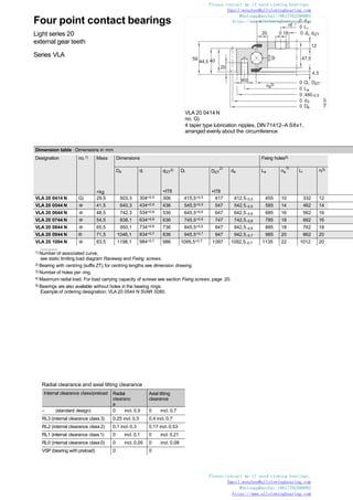
7. Four point contact bearings
Standard series 20
external gear teeth
Series VSA
VSA 20 0414 N
no. G)
4 taper type lubrication nipples, DIN 71412–A S8x1,
arranged evenly about the circumference
0 14
M12
i
44,5
4,5
a
n 3)
20
56
44,5 40
0 Li
0 di, diZT
10atZT
0 Di, DiZT
0 La
0 480-0,5
0 d0
0 Da
132
323a
1) Number of associated curve,
see static limiting load diagram Raceway and Fixing screws.
2) Bearing with centring (suffix ZT), for centring lengths see dimension drawing.
3) Number of holes per ring.
4) Maximum radial load. For load carrying capacity of screws see section Fixing screws, page 20.
Please contact me if need slewing bearings.
Email:wenchen@allslewingbearing.com
Whatsapp&wechat:+8617702586093
https://www.allslewingbearing.com
Dimension table · Dimensions in mm
Designation no.1) Mass
=kg
Dimensions Fixing holes
Da di diZT
2)
+IT8
Di
2)
DiZT
+IT8
da La na
3) Li
3)
ni
VSA 20 0414 N G) 31 503,3 342+0,5 344 415,5+0,5 417 412,5–0,5 455 20 368 24
VSA 20 0544 N @ 43 640,3 472+0,5 474 545,5+0,5 547 542,5–0,5 585 28 498 32
VSA 20 0644 N @ 52 742,3 572+0,6 574 645,5+0,6 647 642,5–0,6 685 32 598 36
VSA 20 0744 N @ 59 838,1 672+0,6 674 745,5+0,6 747 742,5–0,6 785 36 698 40
VSA 20 0844 N @ 71 950,1 772+0,6 774 845,5+0,6 847 842,5–0,6 885 36 798 40
VSA 20 0944 N ® 77 1046,1 872+0,7 874 945,5+0,7 947 942,5–0,7 985 40 898 44
VSA 20 1094 N @ 91 1198,1 1022+0,7 1024 1095,5+0,7 1097 1092,5–0,7 1135 44 1048 48
Radial clearance and axial tilting clearance
Internal clearance class/preload Radial
clearanc
e
Axial tilting
clearance
– (standard design) 0 incl. 0,3 0 incl. 0,53
RL2 (internal clearance class2) 0,1 incl. 0,3 0,17 incl. 0,53
RL1 (internal clearance class1) 0 incl. 0,1 0 incl. 0,21
RL0 (internal clearance class0) 0 incl. 0,05 0 incl. 0,08
VSP (bearing with preload) 0 0
Please contact me if need slewing bearings.
Email:wenchen@allslewingbearing.com
Whatsapp&wechat:+8617702586093
https://www.allslew
n
in3g)bearin0g.dcaom
13. Four point contact bearings
Standard series 25
external gear teeth
Series VSA
VSA 25
4 taper type lubrication nipples, DIN 71412–A M10x1,
no. G) and @ arranged evenly about the circumference;
no. @ and @ = arranged evenly about the circumference
M20
0 d
0 Li
022 0 di, diZT
0 Di, DiZT
0 La
0 d0
0 Da
nB
3)
54
19
B
n 3)
40
80
71
15atZT
132
160a
1) Number of associated curve,
see static limiting load diagram Raceway and Fixing screws.
2) Bearing with centring (suffix ZT), for centring lengths see dimension drawing.
3) Number of holes per ring.
4) Maximum radial load. For load carrying capacity of screws see section Fixing screws, page 20.
Please contact me if need slewing bearings.
Email:wenchen@allslewingbearing.com
Whatsapp&wechat:+8617702586093
https://www.allslewingbearing.com
Dimension table · Dimensions in mm
Designation no.1) Mass
=kg
Dimensions Fixing holes Fixing screws
Fr perm
(friction locking)4)
kN
Da di diZT
2)
+IT8
Di
D 2)
iZT
+IT8
da La Li nB
3)
VSA 25 0755 N G) 128 898 655 657 753 755 757 816 695 24 290,4
VSA 25 0855 N @ 145 997 755 757 853 855 857 916 795 28 338,8
VSA 25 0955 N @ 155 1096 855 857 953 955 957 1016 895 30 363
VSA 25 1055 N @ 171 1198 955 957 1053 1055 1057 1116 995 30 363
Please contact me if need slewing bearings.
Email:wenchen@allslewingbearing.com
Whatsapp&wechat:+8617702586093
https://www.allslewingbearing.a
com
15. Four point contact bearings
Standard series 25
internal gear teeth
Series VSI
VSI 25
4 taper type lubrication nipples, DIN 71412–A M10x1,
no. G) and @ arranged evenly about the circumference
and recessed;
no. @ and @ = arranged evenly about the circumference
0 di
0 d0
0 Li
0 da, daZT
B
n 3)
54
19
80
0 22
0 La
0 Di
nB
M20
40
71
15atZT
132
161a
1) Number of associated curve,
see static limiting load diagram Raceway and Fixing screws.
2) Bearing with centring (suffix ZT), for centring lengths see dimension drawing.
3) Number of holes per ring.
4) Maximum radial load. For load carrying capacity of screws see section Fixing screws, page 20.
Please contact me if need slewing bearings.
Email:wenchen@allslewingbearing.com
Whatsapp&wechat:+8617702586093
https://www.allslewingbearing.com
Dimension table · Dimensions in mm
Designation no.1) Mass
=kg
Dimensions Fixing holes Fixing screws
Fr perm
(friction locking)4)
kN
Da DaZT
2)
–IT8
di Di da daZT
2)
–IT8
La Li nB
3)
VSI 25 0755N G) 119 855 853 610 753 757 755 815 694 24 290,4
VSI 25 0855N @ 137 955 953 710 853 857 855 915 794 28 338,8
VSI 25 0955N @ 149 1055 1053 810 953 957 955 1015 894 30 363,3
VSI 25 1055N @ 165 1155 1153 910 1053 1057 1055 1115 994 30 363,3
Please contact me if need slewing bearings.
Email:wenchen@allslewingbearing.com
Whatsapp&wechat:+8617702586093
https://www.a3l)lslewingbearin0g.Dcoam,DaZT
17. Four point contact bearings
Standard series 25
without gear teeth
Series VSU
VSU 25
4 taper type lubrication nipples, DIN 71412–A M10x1,
no. G) and @ arranged evenly about the circumference
and recessed;
no. @ and @ = arranged evenly about the circumference
0 22
0 Li
0 di, diZT
nB3)
54
nB
3)
63
54
15atZT
0 22
atZT15 0 Di
0 La
0 Da, 0 DaZT
132
140
1) Number of associated curve,
see static limiting load diagram Raceway and Fixing screws.
2) Bearing with centring (suffix ZT), for centring lengths see dimension drawing.
3) Number of holes per ring.
4) Maximum radial load. For load carrying capacity of screws see section Fixing screws, page 20.
Please contact me if need slewing bearings.
Email:wenchen@allslewingbearing.com
Whatsapp&wechat:+8617702586093
https://www.allslewingbearing.com
Dimension table · Dimensions in mm
Designation no.1) Mass
=kg
Dimensions
Da DaZT
2)
–IT8
di
2)
diZT
+IT8
Di da
VSU 25 0755 G) 90 855 853 655 657 753 757
VSU 25 0855 @ 101 955 953 755 757 853 857
VSU 25 0955 @ 115 1055 1053 855 857 953 957
VSU 25 1055 @ 128 1155 1153 955 957 1053 1057
Please contact me if need slewing bearings.
Email:wenchen@allslewingbearing.com
Whatsapp&wechat:+8617702586093
https://www.allslewingbea0ridnga
.com
19. Four point contact bearings
external gear teeth
Series VA
0 L
0 Li
0 di, diZT
na 3)
b
H
a
0 d0
0 Da
VA
No. @, @
4 taper type lubrication nipples, DIN 71412,
= arranged evenly about the circumference
0dB
0dB
h
0 Di, DiZT
T
ni
tat ZT
132
325
1) Number of associated curve,
see static limiting load diagram Raceway and Fixing screws.
2) Bearing with centring (suffix ZT), centring lengths (T,t).
No. G), @ not available in design ZT.
3) Number of holes per ring.
4) Maximum radial load. For load carrying capacity of screws see section Fixing screws, page 20.
5) Gear teeth quenched and tempered.
6) No relubrication facility.
Please contact me if need slewing bearings.
Email:wenchen@allslewingbearing.com
Whatsapp&wechat:+8617702586093
https://www.allslewingbearing.com
Dimension table · Dimensions in mm
Designation no.1) Mass
=kg
Dimensions
Da di diZT
2)
+IT8
Di DiZT
2)
+IT8
da H h T t
VA14 0188 V5) G) 7,5 259,36 135 – 189 – 187 35 30 – –
VA16 0235 N @ 13 318,6 171 173 234 236 236 40 35 2,3 6
VA16 0302 N6) @ 14 384 238 – – – 302,3 32 30 – –
VA25 0309 N @ 29,5 408,4 235 237 308 310 310 60 52,5 3 8
Radial clearance and axial tilting clearance
Designation no. Radial
clearanc
e
Axial tilting
clearance
VA14 0188 V G) 0,03 incl. 0,1 0,05 incl.0,2
VA16 0235 N @ 0,04 incl. 0,16 0,07 incl.0,26
VA16 0302 N @ 0,04 incl. 0,16 0,07 incl.0,6
VA25 0309 N @ 0,06 incl. 0,25 0,1 incl. 0,41
Please contact me if need slewing bearings.
Email:wenchen@allslewingbearing.com
Whatsapp&wechat:+8617702586093
https://www.allslewi3n)gbea0ridnag.com
20. VA
No. G)
2 taper type lubrication nipples, DIN 71412–A M10x1,
arranged evenly about the circumference
VA
No. @
M10
x· m= 2
M10 0 135 +0,2
10
20
4
0 136 +-0,5
0 238 -0,07
132
297
0 310
M12 M12
-0,08
0 238-0,07
18 18
3
-
0 240+0,5
132
298
Fixing holes Fixing screws
Fr perm
(friction locking)4)
kN
Gear teeth Tooth force Basic load ratings
La Li n 3)
a n 3)
i dB d0 m z b Fz norm
kN
Fz max
kN
axial radial
dyn.
Ca
kN
stat.
C0a
kN
dyn.
Cr
kN
stat.
C0r
kN
222 154 16 16 – 44,8 248 4 62 26 10,4 15,3 118 410 77 185
275 195 12 12 13 49,6 312 4 78 35 11 16,1 153 345 101 156
343 262 20 20 – 82,6 376 4 94 30 11 16,1 168 445 110 200
359 259 24 24 13 99,1 400 5 80 52,5 12,9 18,8 325 650 215 295
Static limiting load diagram
Fixing screws (supported load)
Static limiting load diagram
Raceway (supportedload)
0
0
40
20
10
60
kNm
50
1
2
30
3
4
Equivalent
static
tilting
moment
load
M0q
200 400 600 800 kN1000
Equivalent static axial bearing load F0q
132
361
0
0
30
40
50
kNm
20 2
1
10
3
4
Equivalent
static
tilting
moment
load
M0q
100 200 300 400 500 600 kN 700
Equivalent static axial bearing load F0q
132
336
Please contact me if need slewing bearings.
Email:wenchen@allslewingbearing.com
Whatsapp&wechat:+8617702586093
Please contact me if need slewing bearings.
Email:wenchen@allslewingbearing.com
Whatsapp&wechat:+8617702586093
https://www.allslewingbearing.com
https://www.allslewingbearing.com
21. Four point contact bearings
internal gear teeth
Series VI
VI
No. G)
2 taper type lubrication nipples, DIN 71412–A M10x1,
arranged evenly about the circumference and partiallyrecessed
0 di
0 d0
0 Li
0 da, daZT
ni
3)
0 La
0 Di
a aZT
b
h
t
H
T
0dB
0dB
a
n 3)
u
132
560
1) Number of associated curve,
see static limiting load diagram Raceway and Fixing screws.
2) Bearing with centring (suffix ZT), centring lengths (T,t).
No. @ not available in design ZT.
3) Number of holes per ring.
4) Maximum radial load. For load carrying capacity of screws see section Fixing screws, page 20.
5) Without seals/gear teeth quenched and tempered.
Please contact me if need slewing bearings.
Email:wenchen@allslewingbearing.com
Whatsapp&wechat:+8617702586093
https://www.allslewingbearing.com
Dimension table · Dimensions in mm
Designation no.1) Mass
=kg
Dimensions
Da DaZT
2)
–IT8
di Di da daZT
2)
–IT8
H h T t u
VI 16 0288 N G) 12 340 338 216 287 289 287 39 34 6 2,5 9,5
VI 14 0326 V5) @ 18 382 – 250 333 320 – 59 – – – –
VI 16 0420 N @ 23 486 484 332 419 421 419 39 34 6 2,5 –
Radial clearance and axial tilting clearance
Designation no. Radial
clearanc
e
Axial tilting
clearance
VI 16 0288 N G) 0,04 incl. 0,16 0,07 incl. 0,26
VI 14 0326 V @ 0,03 incl. 0,08 0,08 incl. 0,18
VI 16 0420 N @ 0,04 incl. 0,16 0,07 incl. 0,26
Please contact me if need slewing bearings.
Email:wenchen@allslewingbearing.com
Whatsapp&wechat:+8617702586093
https://www.allslewingbearin0g.cDom, D
22. VI
No. @
VI
No. @
2 taper type lubrication nipples, DIN 71412–A M6,
arranged evenly about the circumference
20
34
4
0 18
0 11
M10
6
11
53
0 320
+0,040
0 333+0,057
+0,004
x· m = -0,749
0 268+-0,5
132
302
0 di
0 d0
0 Li
0 da, daZT
i
n 3)
h
t
H
0 La
0 Di
a aZT
b
T
0dB
0dB
a
n 3)
132
301
Fixing holes Fixing screws
Fr perm
(friction locking)4)
kN
Gear teeth Tooth force Basic load ratings
La Li n 3)
a n 3)
i dB d0 m z b Fz norm
kN
Fz max
kN
axial radial
dyn.
Ca
kN
stat.
C0a
kN
dyn.
Cr
kN
stat.
C0r
kN
324 252 20 20 9 35 224 4 56 34 12,3 17,8 165 420 108 190
362 290 8 8 – 22,4 255,5 3,5 73 40 10,8 16,1 83 206 78 93
462 378 16 16 14 66,1 340 4 85 34 12,3 17,8 191 620 125 275
Static limiting load diagram
Fixing screws (supported load)
Static limiting load diagram
Raceway (supportedload)
0
0
20
30
10
50
kNm
40
1
2
3
Equivalent
static
tilting
moment
load
M0q
100 200 300 400 500 600 kN 700
Equivalent static axial bearing load F0q
132
366
0
0
20
30
40
10
Equivalent
static
tilting
moment
load
M0q
100 200 300 400 500 600kN700
Equivalent static axial bearing load F0q
60
kNm 3
50
2
1
132
348
Please contact me if need slewing bearings.
Email:wenchen@allslewingbearing.com
Whatsapp&wechat:+8617702586093
Please contact me if need slewing bearings.
Email:wenchen@allslewingbearing.com
Whatsapp&wechat:+8617702586093
https://www.allslewingbearing.com
https://www.allslewingbe0arDing,.Dcom
23. Four point contact bearings
without gear teeth
Series VU
0 Li
0 L
0 di, diZT
ni 3)
h
t
na3)
T
h
u
H
0 Di
a
0 Da, 0 DaZT
VU
No. G), @, @
2 taper type lubrication nipples, DIN 71412, arranged evenly
about the circumference and partially recessed
0dB
0dB
132
551
1) Number of associated curve,
see static limiting load diagram Raceway and Fixing screws.
2) Bearing with centring (suffix ZT), centring lengths (T,t).
No. @ not available in design ZT.
3) Number of holes per ring.
4) Maximum radial load. For load carrying capacity of screws see section Fixing screws, page 20.
5) Inner ring through hardened.
Please contact me if need slewing bearings.
Email:wenchen@allslewingbearing.com
Whatsapp&wechat:+8617702586093
https://www.allslewingbearing.com
Dimension table · Dimensions in mm
Designation no.1) Mass
=kg
Dimensions
Da DaZT
2)
–IT8
di
2)
diZT
+IT8
Di da H h T t u
max.
VU 14 0179 G) 7 234 232 124,5 126,5 178 180 35 30 5 5 3
VU 20 0220 @ 16 302 300 138 140 219 221 46 41 6 6 –
VU 13 02255) @ 5,4 290 – 200 – 237,6 213 24 24 – – –
VU 20 0260 @ 15 329 327 191 193 259 261 46 41 7 7 2
VU 14 0325 @ 12 380 378 270 272 324 326 35 30 5 5 3
VU 25 0380 ® 44 485 483 275 277 379 381 55 50 8 8 –
Please contact me if need slewing bearings.
Email:wenchen@allslewingbearing.com
Whatsapp&wechat:+8617702586093
https://www.allslewingbea0ridnga.com
24. VU
No. @, ®
2 taper type lubrication nipples, DIN 71412–A M10x1,
arranged evenly about the circumference and recessed
VU
No. @
3 taper type lubrication nipples, DIN 71412–C M8x1,
arranged evenly about the circumference
ni 3)
h
0 da
0 Li
0 di, diZT
t
na3)
T
h
H
0 Di
0 La
0 Da, 0 DaZT
0dB
0dB
132
303
0 200+0,03
M12
132
304
Fixing holes Fixing screws
Fr perm
(friction locking)4)
kN
Basic load ratings Internal clearance
La Li na
3) ni
3) dB axial radial Radial
clearanc
e
Axial tilting
clearance
dyn.
Ca
kN
stat.
C0a
kN
dyn.
Cr
kN
stat.
C0r
kN
214 144,5 12 12 11 33,6 115 255 75 114 0,04 incl. 0,14 0,07 incl. 0,23
270 170 10 10 18 78 201 435 132 197 0,05 incl. 0,2 0,08 incl. 0,33
270 – 6 – – 19,8 49 87 46 39,5 0,02 incl. 0,06 0,05 incl. 0,16
305 215 20 20 14 82,6 217 520 143 233 0,05 incl. 0,2 0,08 incl. 0,33
360 290 24 24 11 67,2 146 460 95 208 0,04 incl. 0,14 0,07 incl. 0,23
453 307 16 16 18 124,8 350 800 230 360 0,06 incl. 0,25 0,11 incl. 0,41
Static limiting load diagram
Fixing screws (supported load)
Static limiting load diagram
Raceway (supportedload)
0
0
20
30
10
50
kNm
40
2
4
1
3
6
5
Equivalent
static
tilting
moment
load
M0q
100 200 300 400 500 kN600
Equivalent static axial bearing load F0q
132
365
0
0
20
30
100 200 300 400 500 600 700 800 900
kN
1
10
3
2
5
Equivalent
static
tilting
moment
load
70
kNm 6
60
M0q 50
40
4
Equivalent static axial bearing load F0q
132
339
Please contact me if need slewing bearings.
Email:wenchen@allslewingbearing.com
Whatsapp&wechat:+8617702586093
Please contact me if need slewing bearings.
Email:wenchen@allslewingbearing.com
Whatsapp&wechat:+8617702586093
https://www.allslewingbearing.com
https://www.allslewingbearing.com
25. Four point contact bearings
without gear teeth
Series VU
0 Li
0 L
0 di, diZT
ni 3)
h
t
na3)
T
h
H
0 Di
a
0 Da, 0 DaZT
VU
No. @ to @
Taper type lubrication nipples, DIN 71412,
= arranged evenly about the circumference
0dB
0dB
132
303
1) Number of associated curve,
see static limiting load diagram Raceway and Fixing screws.
2) Bearing with centring (suffix ZT), centring lengths (T, t).
3) Number of holes per ring.
4) Maximum radial load. For load carrying capacity of screws see section Fixing screws, page 20.
Please contact me if need slewing bearings.
Email:wenchen@allslewingbearing.com
Whatsapp&wechat:+8617702586093
https://www.allslewingbearing.com
Dimension table (continued) · Dimensions in mm
Designation no.1) Mass
=kg
Dimensions
Da DaZT
2)
–IT8
di diZT
2)
+IT8
Di da H h T t
VU 20 0405 @ 25 474 472 336 338 404 406 46 41 7 7
VU 25 0433 ® 41 522 520 344 346 432 434 55 50 8 8
VU 30 0574 @ 82 680 678 468 470 572 576 68 61 10 10
VU 36 0680 @ 120 795 793 565 567 678 682 79 72 11 11
Please contact me if need slewing bearings.
Email:wenchen@allslewingbearing.com
Whatsapp&wechat:+8617702586093
https://www.allslewingbea0ridnga.com
27. Crossed roller bearings
Standard series 14
external gear teeth
Series XSA
XSA 14 0414 N
No. G)
4 taper type lubrication nipples, DIN 71412–A M8x1,
arranged evenly about the circumference
0 14
M12
a
0 Li
0 di
ni
3)
4,5
10
a
n 3)
20
56
44,5 40
C
A
D
44,5
B
0 Di
0 La
0 480-0,5
0 d0
0 Da
132
305a
1) Number of associated curve,
see static limiting load diagram Raceway and Fixing screws.
2) Bearings always with centring, for centring lengths see dimension drawing.
3) Number of holes per ring.
4) Maximum radial load. For load carrying capacity of screws see section Fixing screws, page 20.
Please contact me if need slewing bearings.
Email:wenchen@allslewingbearing.com
Whatsapp&wechat:+8617702586093
https://www.allslewingbearing.com
Dimension table · Dimensions in mm
Designation No.1) Mass
=kg
Dimensions Fixing holes
Da
2)
di
+IT7
Di
2)
+IT7
da La
3)
na Li ni
3)
XSA 14 0414 N G) 32 503,3 344 417 413–0,5 455 20 368 24
XSA 14 0544 N @ 44 640,3 474 547 543–0,5 585 28 498 32
XSA 14 0644 N @ 52 742,3 574 647 643–0,6 685 32 598 36
XSA 14 0744 N @ 59 838,1 674 747 743–0,6 785 36 698 40
XSA 14 0844 N @ 71 950,1 774 847 843–0,6 885 36 798 40
XSA 14 0944 N ® 77 1046,1 874 947 943–0,7 985 40 898 44
XSA 14 1094 N @ 91 1198,1 1024 1097 1093–0,7 1135 44 1048 48
Running accuracy (to raceway)
Designation No. A B C D
XSA 14 0414 N G) 0,04 0,04 0,06 0,06
XSA 14 0544 N @ 0,04 0,04 0,07 0,06
XSA 14 0644 N @ 0,05 0,05 0,08 0,07
XSA 14 0744 N @ 0,05 0,05 0,08 0,08
XSA 14 0844 N @ 0,05 0,05 0,09 0,08
XSA 14 0944 N ® 0,06 0,06 0,09 0,09
XSA 14 1094 N @ 0,07 0,07 0,11 0,11
Please contact me if need slewing bearings.
Email:wenchen@allslewingbearing.com
Whatsapp&wechat:+8617702586093
https://www.allslewingbeari0ngd.com
28. XSA 14
No. @ to @
4 taper type lubrication nipples, DIN 71412–A M8x1,
arranged evenly about the circumference
0 14
M12
0 da
0 Li
0 di
0 Di
0 La
0 d0
0 Da
ni
3)
44,5
4,5
a
n 3)
20
44,5
56
C
A
10
D
B
132
566
Fixing screws
Fr perm
(friction locking)4)
kN
Gear teeth Tooth force Basic load ratings Internal clearance
Preload
d0 m z Fz norm
kN
Fz max
kN
axial radial
dyn.
Ca
kN
stat.
C0a
kN
dyn.
Cr
kN
stat.
C0r
kN
82,6 495 5 99 15,9 23,6 229 520 146 250 0,01 incl. 0,03
115,6 630 6 105 21,3 31,5 270 680 170 330 0,01 incl. 0,03
132,2 732 6 122 21,3 31,5 290 800 185 395 0,01 incl. 0,04
148,7 828 6 138 21,3 31,5 315 930 200 455 0,01 incl. 0,04
148,7 936 8 117 28,3 42 340 1050 215 510 0,01 incl. 0,04
165,2 1032 8 129 28,3 42 360 1170 227 580 0,01 incl. 0,05
181,7 1184 8 148 28,3 42 390 1360 246 670 0,01 incl. 0,05
Static limiting load diagram
Fixing screws (supported load)
Static limiting load diagram
Raceway (supportedload)
0
0
100
120
40
80
60
20 1
2
4
3
5
6
7
Equivalent
static
tilting
moment
load
200
kNm
180
160
M0q140
200 400 600 800 kN1000
Equivalent static axial bearing load F0q
132
358
0
0
50
100
150
200
250
200 400 600 800 1000 1200 1400
350
kNm
300
kN
1
3
2
4
5
6
7
Equivalent
static
tilting
moment
load
M0q
Equivalent static axial bearing load F0q
132
287
Please contact me if need slewing bearings.
Email:wenchen@allslewingbearing.com
Whatsapp&wechat:+8617702586093
https://www.allslewingbearing.com
Please contact me if need slewing bearings.
Email:wenchen@allslewingbearing.com
Whatsapp&wechat:+8617702586093
https://www.allslewingbearing.com
29. Crossed roller bearings
Standard series 14
internal gear teeth
Series XSI
0 Li
0 da
XSI 14 0414 N
No. G)
4 taper type lubrication nipples, DIN 71412–A M8x1,
arranged evenly about the circumference
ni3)
10
44,5
4,5
56
0 14
0 La
0 Di
na
3) a
20
40 44,5
C
A
D
B M12 0 di
0 d0
0 350+0,5
132
306a
1) Number of associated curve,
see static limiting load diagram Raceway and Fixing screws.
2) Bearings always with centring, for centring lengths see dimension drawing.
3) Number of holes per ring.
4) Maximum radial load. For load carrying capacity of screws see section Fixing screws, page 20.
Please contact me if need slewing bearings.
Email:wenchen@allslewingbearing.com
Whatsapp&wechat:+8617702586093
https://www.allslewingbearing.com
Dimension table · Dimensions in mm
Designation No.1) Mass
=kg
Dimensions Fixing holes
Da
2)
–IT7
di Di
2)
da
–IT7
La
3)
na Li
3)
ni
XSI 14 0414N G) 31 484 325 415+0,5 411 460 24 375 24
XSI 14 0544N @ 43 614 444 545+0,5 541 590 32 505 32
XSI 14 0644N @ 50 714 546 645+0,6 641 690 36 605 36
XSI 14 0744N @ 58 814 648 745+0,6 741 790 40 705 40
XSI 14 0844N @ 69 914 736 845+0,6 841 890 40 805 40
XSI 14 0944N ® 76 1014 840 945+0,7 941 990 44 905 44
XSI 14 1094N @ 91 1164 984 1095+0,7 1091 1140 48 1055 48
Running accuracy (to raceway)
Designation No. A B C D
XSI 14 0414 N G) 0,04 0,04 0,06 0,06
XSI 14 0544 N @ 0,04 0,04 0,07 0,07
XSI 14 0644 N @ 0,05 0,05 0,08 0,08
XSI 14 0744 N @ 0,05 0,05 0,09 0,08
XSI 14 0844 N @ 0,06 0,06 0,09 0,09
XSI 14 0944 N ® 0,06 0,06 0,11 0,09
XSI 14 1094 N @ 0,07 0,07 0,11 0,11
Please contact me if need slewing bearings.
Email:wenchen@allslewingbearing.com
Whatsapp&wechat:+8617702586093
https://www.allslewingbea0
rin
D
g.com
33. Crossed roller bearings
external gear teeth
Series XA
Crossed roller bearings
internal gear teeth
Series XI 0 L
na 3)
b
H
a
0 d0
0 Da
XA
No. G)
2 taper type lubrication nipples, DIN 71412–A M10x1,
arranged evenly about the circumference
0dB
0dB
h
0 Di,DiZT
T
ni
0 Li
0 di, diZT
t
132
317
1) Number of associated curve,
see static limiting load diagram Raceway and Fixing screws.
2) Bearing with centring (suffix ZT), centring lengths (T,t). No. @ not available in design ZT.
1) Number of associated curve,
see static limiting load diagram Raceway and Fixing screws.
2) Bearing with centring (suffix ZT), centring lengths (T, t).
3) Number of holes per ring.
4) Maximum radial load. For load carrying capacity of screws see section Fixing screws, page 20.
Please contact me if need slewing bearings.
Email:wenchen@allslewingbearing.com
Whatsapp&wechat:+8617702586093
https://www.allslewingbearing.com
Dimension table · Dimensions in mm
Designation No.1) Mass
=kg
Dimensions Fixing holes
Da di
2)
diZT
+IT8
Di DiZT
2)
+IT8
da H h T t La Li
XA 12 0235 N G) 13,3 318,8 171 173 236士0,2 238 234士0,2 40 35 2,6 6 275 195
XA 20 0352 H5) @3) 34,5 462 274 – 353 – 351 59 54 – – 407 298
Dimension table · Dimensions in mm
Designation No.1) Mass
=kg
Dimensions Fixing holes
Da DaZT
2)
–IT8
di Di da daZT
2)
–IT8
H h T t u La Li
XI 12 0288 N @ 12 340 338 216 289 287 285 38 33 5 2,5 6 324 252
Please contact me if need slewing bearings.
Email:wenchen@allslewingbearing.com
Whatsapp&wechat:+8617702586093
https://www.allslewi3n)gbea0ridnag.com
34. XI
No. @
taper type lubrication nipples, DIN 71412,
= arranged evenly about the circumference and partially
recessed
0 d a
0 Li
0 di
3)
b
11
H
0 Da
0 d0
0dB
0dB
h
ni
0 274+0,081
0 Di
0 380-0,089
0 La
17
n3)
a
a
132
568
XA
No. @
a 1 lubrication hole M12x1, 10 mm deep
0 di
0 d0
0 Li
0 da, daZT
ni 3)
h
t
u
H
0 La
0 Di
b
T
0dB
0dB
a
n 3)
132
315
3) Number of holes per ring.
4) Maximum radial load. For load carrying capacity of screws see section Fixing screws, page 20.
5) Gear teeth hardened.
Fixing screws
Fr perm
(friction locking)4)
kN
Gear teeth Tooth force Basic load ratings Internal
clearanc
e
Preload
na
3) ni
3) dB d0 m z b Fz norm
kN
Fz max
kN
axial radial
dyn.
Ca
kN
stat.
C0a
kN
dyn.
Cr
kN
stat.
C0r
kN
12 12 13 49,6 312 4 78 35 11 16,1 135 235 86 115 0 incl. 0,02
24 24 14 99,1 450 6 75 30 20,9 34,5 335 720 214 355 0 incl. 0,02
Fixing screws
Fr perm
(friction locking)4)
kN
Gear teeth Tooth force Basic load ratings Internal
clearanc
e
Preload
na
3) ni
3) dB d0 m z b Fz norm
kN
Fz max
kN
axial radial
dyn.
Ca
kN
stat.
C0a
kN
dyn.
Cr
kN
stat.
C0r
kN
20 20 9 35 224 4 56 34 12,3 17,8 150 290 95 141 0 incl. 0,02
Static limiting load diagram
Fixing screws (supported load)
Static limiting load diagram
Raceway (supportedload)
0
0
10
5
30
35
kNm
1
2
3
Equivalent
static
tilting
moment
load
M0q 25
20
15
100 200 300 400 500 600 700kN800
Equivalent static axial bearing load F0q
132
362
0
0
40
30
10
20
50
60
kNm
1
2
3
Equivalent
static
tilting
moment
load
M0q
100 200 300 400 500 600 700 kN800
Equivalent static axial bearing load F0q
132
341
Please contact me if need slewing bearings.
Email:wenchen@allslewingbearing.com
Whatsapp&wechat:+8617702586093
Please contact me if need slewing bearings.
Email:wenchen@allslewingbearing.com
Whatsapp&wechat:+8617702586093
https://www.allslewingbearing.com
https://www.allslewingbe0arDian,g.DcaoZmT
35. Crossed roller
bearings
without gear teeth
Series XU
XU
No. ® 2 taper type lubrication nipples,
DIN71412–AM6, arranged evenly about
the circumference and partially recessed
XU
No. G),@
0 da
i
ni 3)
0 L
na3)
u
H h h
T
0 Di
0 La
0 Da,DaZT
0dB
0dB 0 di, diZT
t
132
141
13 H
10
+0,025
tS
0 Da–0,04
0dS M8
0 di
0dB
h
132
308
1) Number of associated curve,
see static limiting load diagram Raceway and Fixing screws.
2) Bearing with centring (suffix ZT), centring lengths (T,t).
No. G)to @ not available in design ZT.
3) Number of holes per ring.
4) Maximum radial load. For load carrying capacity of screws see section Fixing screws, page 20.
5) Special seal.
Please contact me if need slewing bearings.
Email:wenchen@allslewingbearing.com
Whatsapp&wechat:+8617702586093
https://www.allslewingbearing.com
Dimension table · Dimensions in mm
Designation No.1) Mass
=kg
Dimensions
Da DaZT
2)
–IT8
di diZT
2)
+IT8
Di da H h T t u
max.
XU 0500775) G) 1,4 112 – 40 – 77,5 74 22 21 – – –
XU 0600945) @ 2,4 140 – 57 – 94,6 93,4 26 25 – – –
XU 0601115) @ 1,2 145,79 – 76,2 – 111,8 – 15,87 – – – –
XU 0801205) @ 4 170 – 69 – 120,6 119,4 30 – – – –
XU 0801495) @ 3,6 196,85 – 101,6 – 149,6 – 22,22 22,22 – – –
XU 120179 ® 7 234 232 124,5 126,5 180士0,2 178士0,2 35 30 5 5 6
Please contact me if need slewing bearings.
Email:wenchen@allslewingbearing.com
Whatsapp&wechat:+8617702586093
https://www.allslewingbearing.com