All the concept you need on Single Quadrant Chopper Fed DC Drive
- Working
- Duty cycle concept
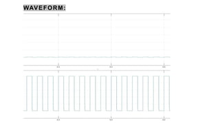
- Waveform
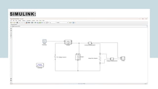
- Simulink/simulation (MATLAB)
- Application
- Advantages
- Disadvantages
Thanks for reading
All the Best
GOVERNMENT ENGINEERING COLLEGE,
VALSAD
ELECTRICALDRIVES
SINGLE QUADRANT CHOPPER FED DC DRIVE
Presented by
Enrollment No. Name
220190109003 Ayush Singh
220190109004 Kanojiya Ritesh C.
220190109008 Mangela Vaishvik V.
220190109009 Mangela Parthiv D.
Department: Electrical, Semester:6th
(2024-25)
2.
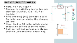
BASIC CIRCUIT DIAGRAM:
Here, Vs = DC supply.
Chopper is switching device (we can
also use MOSFET, IGBT, SCR or
thyristor).
Free wheeling (FD) provides a path
for motor current during the chopper
off time.
Here, load is DC motor which can be
separately excited or series motor.
Both current and voltage are always
positive (unidirectional operation).
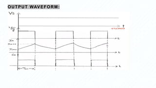
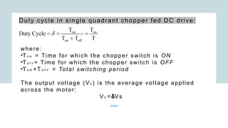
Duty cycle insingle quadrant chopper fed DC drive:
where:
•TO N = Time for which the chopper switch is ON
•TO F F = Time for which the chopper switch is OFF
•TO N +TO F F = Total switching period
The output voltage (V0 ) is the average voltage applied
across the motor:
V0 =δVs
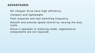
ADVANTAGES:
• DC chopperdrive have high efficiency.
• Compact and lightweight.
• Fast response and fast switching frequency.
• Smooth and precise speed control by varying the duty
cycle.
• Since it operates in motoring mode, regenerative
components are not required.
8.
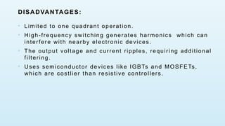
DISADVANTAGES:
• Limited toone quadrant operation.
• High-frequency switching generates harmonics which can
interfere with nearby electronic devices.
• The output voltage and current ripples, requiring additional
filtering.
• Uses semiconductor devices like IGBTs and MOSFETs,
which are costlier than resistive controllers.
9.
APPLICATIONS:
• To controlthe speed of DC motors.
• Industrial conveyor belt drives.
• Fans, blowers, and pumps requiring variable speed
control.
• Robotic arm movement in one direction.
• Traction systems.
• Rolling mills.
10.
CONCLUSION:
The Single QuadrantChopper Fed DC Drive is a fundamental power
electronic converter used to control DC motors. We studied its
operation, simulink modeling and application.