The double disk brake BMG..T has a basic design with a pressure plate that is forced against the brake disk by brake springs when the electromagnet is de-energized, applying the brake. It functions as a dual-circuit brake, so that if one brake fails the other can still stop the load. The brake is automatically applied if power fails or in case of faults in the electric control. Wear monitoring ensures the brake cannot be released if the lining is too worn. Permitted motor/brake combinations are specified.


![3
Basic unit
Basic design
Operating Instructions – BMG..T 11
3 Basic unit
3.1 Basic design
The following figure shows an exemplary sectional drawing and makes it easier to as-
sign components to the spare parts lists. Deviations are possible depending on the
size and design of the brake.
The following figure shows the basic design of BMG..T:
[69]
[52]
[66]
[49]
[157]
[50]
[265]
[53]
[54]
[56]
[57]
[58]
[42]
[73]
[67]
[65]
[68]
[60]
[61]
[95]
[59]
1221413643
[42] Brake endshield [61] Hex nut with gripping part
[49] Pressure plate [65] Pressure ring
[50] Brake spring [66] Sealing strip
[52] Brake plate [67] Counter spring
[53] Manual release lever [68] Complete brake disk
[54] Complete coil body [69] Circular spring
[56] Stud [73] Brake disk
[57] Conical spring [95] Sealing ring
[58] Hex nut with gripping part [157] Clamping strap
[59] Dowel pin [265] Brake spring, red
[60] Stud
21357390/EN
–
03/2016](https://image.slidesharecdn.com/sewelectromagneticbrake-221223173844-8716d536/75/sew-electromagnetic-brake-pdf-11-2048.jpg)

![4
Installation
Electrical installation
Operating Instructions – BMG..T 15
4.2.1 Connecting the microswitch option
Connect the diagnostic unit as shown in the wiring connection diagrams provided with
the motor. Observe the following permitted limit currents:
Permitted limit values Permitted limit values
Maximum connection
voltage
AC 250 V Maximum extra-low
voltage
AC 24 V or
DC 24 V
Maximum current 3 A Maximum current 0.1 A
A subsequent change to extra-low voltage is not permitted.
Function monitoring Wear monitoring Function and wear moni-
toring
BN1
BU1
[2]
[1]
BN1
BU1
[2]
[1] [1]
BN1
BU1
[2]
BN2
BU2
[2]
[3]
[4]
[1] Brake
[2] Microswitch
MP321-1MS
[1] Brake
[2] Microswitch
MP321-1MS
[1] Brake
[2] Microswitch
MP321-1MS
[3] Function monitoring
[4] Wear monitoring
21357390/EN
–
03/2016](https://image.slidesharecdn.com/sewelectromagneticbrake-221223173844-8716d536/75/sew-electromagnetic-brake-pdf-15-2048.jpg)


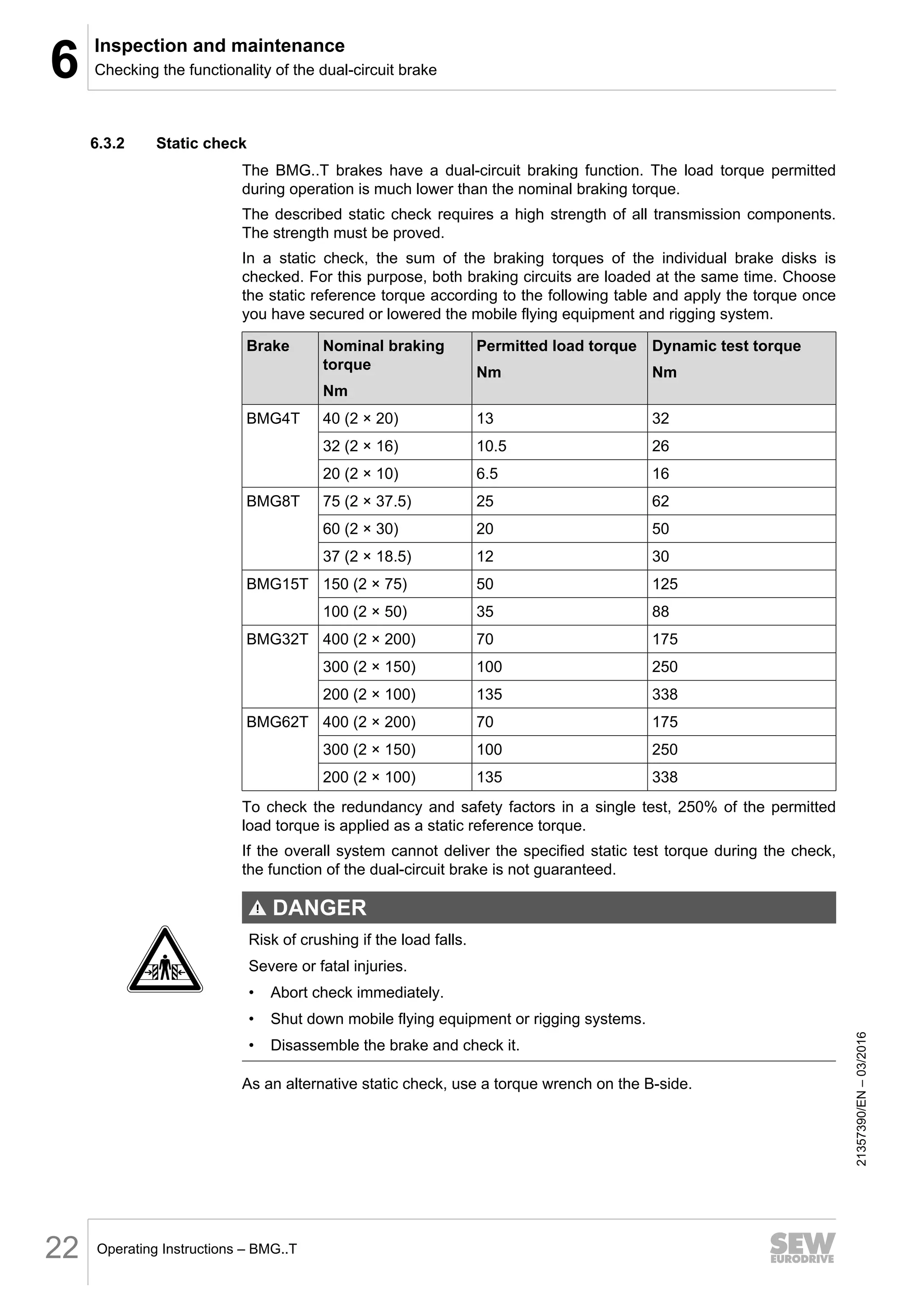
![6
Inspection and maintenance
Checking the functionality of the dual-circuit brake
Operating Instructions – BMG..T 19
DANGER
Risk of crushing if the load falls.
Severe or fatal injuries.
• Any work on the point host or the rigging system may be performed by ad-
equately skilled personnel only.
• Secure the mobile flying equipment or rigging system.
• Lower the mobile flying equipment or rigging system.
2. Remove safety cover and encoder.
3. Remove sealing strip.
4. Release the brake electrically or using the manual brake release.
5. Remove one brake disk from the power flow by inserting 3 distance blocks above
the studs (see the figure on the following page). To do so, turn the adjusting
screws [3] of the distance blocks [1] in counterclockwise direction until the brake
disk [4] is inoperative.
6. Apply brake.
7. Set the working air gap for the brake disk in the power flow to 0.25 mm (see
chapter "Inspection/maintenance" in the "AC Motors" operating instructions).
8. The brake system in the power flow - that is, the one that has not been disabled
using distance blocks – must be able to apply the dynamic reference torque rat-
ings listed in the following table (125% of the permitted load torque).
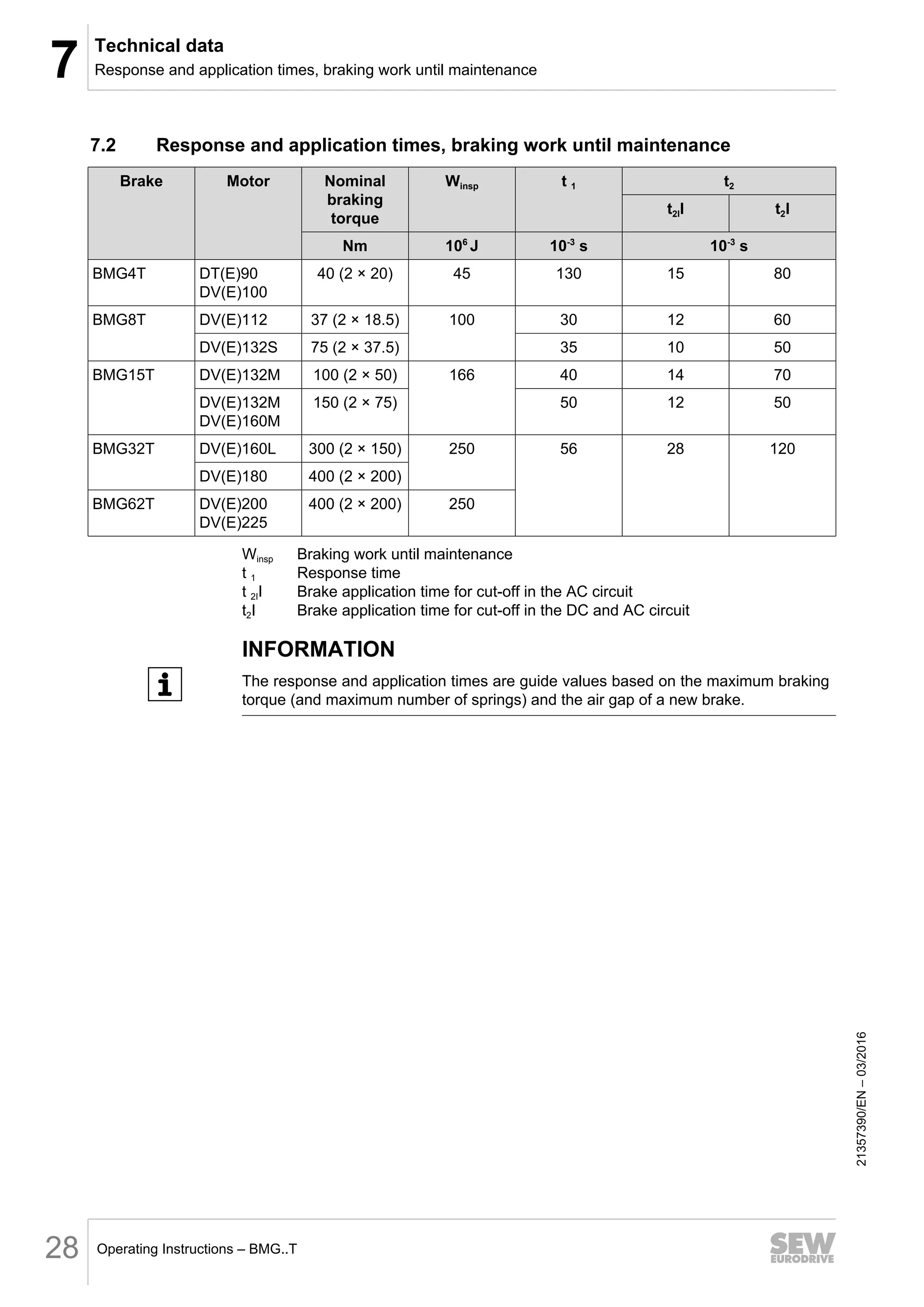
Brake Nominal braking
torque
Nm
Permitted load torque
Nm
Dynamic test torque
Nm
BMG4T 40 (2 × 20) 13 16
32 (2 × 16) 10.5 13
20 (2 × 10) 6.5 8
BMG8T 75 (2 × 37.5) 25 31
60 (2 × 30) 20 25
37 (2 × 18.5) 12 15
BMG15T 150 (2 × 75) 50 62
100 (2 × 50) 35 44
BMG32T 400 (2 × 200) 135 169
300 (2 × 150) 100 125
200 (2 × 100) 70 87.5
BMG62T 400 (2 × 200) 135 169
300 (2 × 150) 100 125
200 (2 × 100) 70 87.5
9. Remove distance blocks.
21357390/EN
–
03/2016](https://image.slidesharecdn.com/sewelectromagneticbrake-221223173844-8716d536/75/sew-electromagnetic-brake-pdf-19-2048.jpg)

![6
Inspection and maintenance
Checking the functionality of the dual-circuit brake
Operating Instructions – BMG..T 21
The following figure shows the test of the dual-circuit brake function with distance
blocks:
[1]
[2]
[3]
[4]
[5]
1221411211
[1] Distance block (3x) [4] Brake disk not in the power flow
[2] Air gap [5] Brake disk in the power flow
[3] Adjusting screw
21357390/EN
–
03/2016](https://image.slidesharecdn.com/sewelectromagneticbrake-221223173844-8716d536/75/sew-electromagnetic-brake-pdf-21-2048.jpg)
![6
Inspection and maintenance
Inspection/maintenance of the microswitch
Operating Instructions – BMG..T 23
6.4 Inspection/maintenance of the microswitch
6.4.1 Basic design
[66] [49]
[560]
[561] [557]
[555]
[558]
[559]
[556]
[562]
1529021963
[49] Pressure plate for microswitch [557] Pin
[66] Sealing strip for microswitch [558] Hex head screw
[555] Microswitch [560] Hex head screw
[556] Angle bracket [561] Stud
[559] Pan head screw [562] Washer
21357390/EN
–
03/2016](https://image.slidesharecdn.com/sewelectromagneticbrake-221223173844-8716d536/75/sew-electromagnetic-brake-pdf-23-2048.jpg)
![6 Inspection and maintenance
Inspection/maintenance of the microswitch
Operating Instructions – BMG..T
24
6.4.2 Inspection/maintenance of microswitch for function monitoring
DANGER
Risk of crushing if the drive starts up unintentionally.
Severe or fatal injuries.
• Disconnect the motor from the power supply before starting work and safeguard
it against accidental startup.
• Carefully observe the steps described below.
1. Control and check the working air gap according to chapter "Inspection/mainten-
ance work BMG05-8, BMG15-62 brake" in the "DR/DV/DT/DTE/DVE AC Motors,
CT/CV Asynchronous Servomotors" operating instructions.
2. Screw hex head screw [560] against the actuator of microswitch [555] until it
switches over (brown-blue contacts closed).
While screwing, apply the hex nut [561] to eliminate the floating clearance from the
thread.
3. Turn hex head screw [560] back until microswitch [555] switches back (contacts
brown-blue open).
4. To ensure operational reliability, turn hex head screw [560] further back by one-
sixth of a revolution (0.1 mm).
5. Tighten hex nut [561], while doing so, hold hex head screw [560] to keep it in the
correct position.
6. Switch the brake on and off several times. Check whether the microswitch opens
and closes reliably in any motor shaft position. Therefore, turn the motor shaft
manually several times.
21357390/EN
–
03/2016](https://image.slidesharecdn.com/sewelectromagneticbrake-221223173844-8716d536/75/sew-electromagnetic-brake-pdf-24-2048.jpg)
![6
Inspection and maintenance
Inspection/maintenance of the microswitch
Operating Instructions – BMG..T 25
6.4.3 Inspection/maintenance of microswitch for wear monitoring
DANGER
Risk of crushing if the drive starts up unintentionally.
Severe or fatal injuries.
• Disconnect the motor from the power supply before starting work and safeguard
it against accidental startup.
• Carefully observe the steps described below.
1. Control and check the working air gap according to chapter "Inspection/mainten-
ance work BMG05-8, BMG15-62 brake" in the "DR/DV/DT/DTE/DVE AC Motors,
CT/CV Asynchronous Servomotors" operating instructions.
2. Screw hex head screw [560] against the actuator of microswitch [555] until it
switches over (brown-blue contacts closed).
While screwing, apply the hex nut [561] to eliminate the floating clearance from the
thread.
3. Loosen hex head screw [560] towards the microswitch [555] by half a turn.
4. To prevent changes to the settings, tighten the hex nut [561] while holding the hex
head screw [560] in place.
5. If the brake lining reaches the wear limit, the microswitch automatically switches
back (brown-blue contacts open) and activates a relay or a signal.
6.4.4 Inspection/maintenance of the microswitch for function and wear monitoring
If two microswitches are mounted to one brake, both monitoring statuses can be real-
ized. In this case, set the microswitch for wear monitoring before you set the mi-
croswitch for function monitoring.
21357390/EN
–
03/2016](https://image.slidesharecdn.com/sewelectromagneticbrake-221223173844-8716d536/75/sew-electromagnetic-brake-pdf-25-2048.jpg)