1. HONDA
BFI 15A-130A
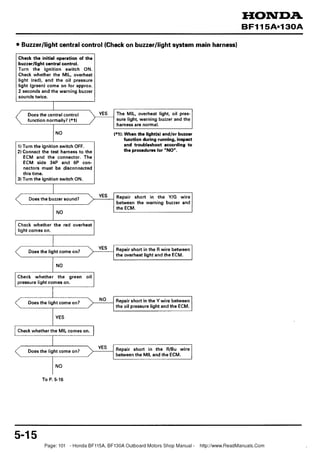
Buzzerllight central control (Check on buzzerllight system main harness)
Check the initial operation of the
buzzerllight central control.
Turn the ignition switch ON.
Check whether the MIL, overheat
light (red), and the oil pressure
light (green) come on for approx.
2 seconds and the warning buzzer
sounds twice.
Does the central control
function normally? (*1) > YES The MIL, overheat light, oil pres-
sure light, warning buzzer and the
harness are normal.
(*I): the light(s) and/or buzzer
When
I function during running, inspect
1) Turn the ignition switch OFF. and troubleshoot according t o
2) Connect the test harness to the the procedures for "NO".
ECM and the connector. The
ECM side 34P and 6P con-
nectors must be disconnected
this time.
3) Turn the ignition switch ON.
I
YES Repair short in the Y/G wire
Does the buzzer sound?
between the warning buzzer and
the ECM.
NO
Check whether the red overheat
I
Does the light come on? Repair short in the R wire between
the overheat light and the ECM.
NO
Check whether the green oil
I
Does the light come on? Repair short in the Y wire between
the oil pressure light and the ECM.
I
Check whether the MIL comes on.
I
Does the light come on? Repair short in the R/Bu wire
between the MIL and the ECM.
5-1 5
Page: 101 - Honda BF115A, BF130A Outboard Motors Shop Manual - http://www.ReadManuals.Com
2. From P. 5-15
JUMPER
1) Turn the ignition switch OFF. WIRE
2) Connect the test box's A3 termi-
nal to the body ground.
3) Turn the ignition switch ON.
4) Check whether the warning
buzzer sounds.
Repair open in the Y/G wire
N0 between the warning buzzer and TEST HARNESS
Does the buzzer sound? the ECM.
Check the warning buzzer (P. 17-
30).
Check the remote control system
harnesses and the ignition
1) Turn the ignition switch OFF. switch (P. 17-29).
2) Connect the test box's A27
terminal to the body ground.
3) Turn the ignition switch ON.
4) Check whether the red overheat
light comes on. JUMPER WIRE 1 A27
I
*Repair open in the R wire
between the overheat light and
Does the light come on? the ECM.
Replace the blown overheat light
bulb.
Check the remote control system
I
harnesses and the ignition
1) Turn the ignition switch OFF. switch (P. 17-29).
2) Connect the test box's A19
terminal to the body ground.
3) Turn the ignition switch ON.
4) Check whether the green oil
pressure light comes on. l 9 JUMPER WIRE
* Repair open in the Y wire
YES between the oil pressure light
Does the light come on?
and the ECM.
Replace the blown oil pressure JUMPER
light bulb. WIRE
I
Check the remote control system
1) Turn the ignition switch OFF. harnesses and the ignition
2) Connect the test box's A1 termi- switch (P. 17-29).
nal to the body ground.
3) Turn the ignition switch ON.
4) Check whether the MIL comes
on.
Perform the troubleshooting flow
Does the light come on? chart of "MIL does not come on.
(MIL does not come on for 2 sec-
onds with the ignition switch
YES
ON.)" (P. 5-11).
1) Turn the ignition switch OFF.
2) Disconnect the alternator 4P
connector.
3) Check for continuity between
the test box's A5 terminal and
the body ground.
Page: 102 - Honda BF115A, BF130A Outboard Motors Shop Manual - http://www.ReadManuals.Com
3. From I? 5-16
I
YES Repair short in the WIBu wire
Is there continuity? between the alternator and the TEST HARNESS ALTERNATOR
ECM. 4P CONNECTOR
I I
NO
Check for continuity between the
alternator 4P connector No.4
(W/Bu) terminal and the test box's
A5 terminal. ACG
(WIBul
I
Repair open in the WIBu wire Viewing connector
Is there continuity? from the front side
between the alternator and the
1) Turn the ignition switch OFF.
2) Disconnect the connector from
the oil pressure switch.
3) Check for continuity between
the test box's A23 terminal and
the body ground.
Is there continuity? Repair short in the Y/R wire
between the oil pressure switch
I 1 and the ECM. 1
Check for continuity between the
test box's A23 terminal and the
YIR terminal of the harness side
oil pressure switch connector.
YES
1 Repair open in the YIR wire
between the oil pressure switch
and the ECM.
SWITCH
CONNECTOR
OPS (YIR)
1) Turn the ignition switch OFF.
2) Connect the oil pressure switch
connector.
3) Check for continuity between
the test box's A23 terminal and
the body ground.
I
No Replace the oil pressure switch (P.
Is there continuity?
5-77).
1 YES
Buzzerllight system main harness
is normal.
When the buzzerllight system
shows an erroneous operation,
substitute with a known-good
ECM and recheck.
Page: 103 - Honda BF115A, BF130A Outboard Motors Shop Manual - http://www.ReadManuals.Com
4. Idling speed is low or trolling speed is high.
Check the idle control system and the neutral position. If it checked out normal, perform the inspection and trouble-
shooting according to the following flow chart.
1) Set the lever in the "N" (Neutral)
position and start the engine.
2) Warm up the engine sufficiently
and disconnect the neutral
switch 2P connector.
I
I
Does the engine speed change? ECM and main harness are
normal.
Check the neutral switch (P. 17-
NO 26).
Check the idle control system (P. TEST HARNESS
1) Turn the ignition switch OFF. 5-30).
2) Connect the test harness to the 000 ooooooooooooooooo
ECM and the connector. Note
that the ECM side 34P con-
nector and the 6P connector
must be disconnected this time.
3) With the neutral switch 2P
connector disconnected, check
for continuity between the test
box's A30 terminal and the
body ground.
YES Repair short in the BIIG wire
Is there continuity? between the ECM and the neutral
I switch.
Check for continuity between the
test box's A30 terminal and the
No.1 (BIIG) terminal of the neutral
switch 2P connector.
NO Repair open in the BI/G wire 2P CONNECTOR
Is there continuity? between the ECM and the neutral NLSW
switch. (BIIG)
YES
I
Viewing connector
Substitute a known-good ECM
from the front side
and recheck.
5-18
Page: 104 - Honda BF115A, BF130A Outboard Motors Shop Manual - http://www.ReadManuals.Com
5.
6. b. MAP SENSOR
MIL blinks 3 times with service check connector shorted (P.5-51.
1) Reset the ECM (P. 5-61.
2) Start the engine and let it idle.
3) Check the MIL for the number of
MAP SENSOR
blinks. 3P CONNECTOR
NO Loose connection between the
Does the MIL blink 3 times? ECM and the MAP sensor. Con-
nect securely.
YES
I
1) Turn the ignition switch OFF.
2) Disconnect the MAP sensor 3P
connector. Viewing connector
3) Turn the ignition switch ON. f r o m t h e front side
4) Connect the positive (+) tester
lead to the No.3 (Br/Y) terminal
of the harness side MAP sensor
3P connector, and the negative
(-) tester lead to the body
ground. Measure the voltage.
I Connect the positive (+I tester lead
to the No.3 (B~/Y) terminal of the
YES harness side MAP sensor 3P con-
nector, and the negative (-) tester
lead to the No.2 (GI terminal. Viewing connector
f r o m the f r o n t side
Is there 4.75 - 5.25 V ?
" Repair open in the G wire between the
ECM and the MAP sensor.
I
I YES
Viewing connector
Connect the positive (+)tester lead
from the front side
to the No.1 (WIR) terminal of the A
harness side MAP sensor 3P con-
nector, and the negative (-) tester
lead to the No.2 (G) terminal.
Measure the voltage.
v1 Is there 4.75 - 5.25 V ?
Repair open or short in the WIR wire
between the ECM and the MAP sensor.
-Substitute a known-good ECM and
recheck.
Page: 106 - Honda BF115A, BF130A Outboard Motors Shop Manual - http://www.ReadManuals.Com
7. HONDA
BF115A~130A
From P. 5-20
I
1) Turn the ignition switch OFF. TEST HARNESS
2) Connect the MAP sensor 3P
connector.
3) Connect the test harness to the
ECM and the connector.
4) Turn the ignition switch ON.
5) Measure the voltage between
the test box's positive (t) A6
'
terminal and the negative (-)
A33 terminal.
NO
Is there 2.76 - 2.96 V ? Replace the MAP sensor (P. 5-57).
and recheck.
From P. 5-20
I
1)Turn the ignition switch OFF.
2) Connect the test harness to the
ECM and the connector. Note
that the test harness sensor
connector must be discon-
nected this time.
3) Turn the ignition switch ON.
4) Measure the voltage between
the test box's positive (+I A8
terminal and the negative (-)
A33 terminal.
Is there 4.75 - 5.25 V ? Repair open in the B r N wire
between the ECM and the MAP
sensor.
Substitute a known-good ECM
and recheck.
5-21
Page: 107 - Honda BF115A, BF130A Outboard Motors Shop Manual - http://www.ReadManuals.Com
8. HONDA
B F I 15AeI 30A
c. TP SENSOR
MIL blinks 7 times with service check connector shorted (P. 5-51.
Check that the throttle cable is adjusted properly (P. 3-10) before starting the TP sensor inspection1troubleshooting.
1) Reset the ECM (P. 5-6).
TP SENSOR
2) Start the engine. 3P CONNECTOR
3) Check the MIL for the number of
blinks.
Does it blink 7 times?
1Loose connection between the 1
1ECM and the TP sensor. Connect 1 wl
1 securely. I
1) Turn the ignition switch OFF.
2) Disconnect the TP sensor 3P
connector. Wewing connector
3) Turn the ignition switch ON. from the front side
4) Connect the positive (+I tester
lead to the No.1 (Brff) terminal
of the harness side TP sensor
3P connector, and the negative TEST HARNESS
(-1 tester lead to the N0.3 (GI
terminal of the 3P connector.
Measure the volta~e.
I
1) Turn the ignition switch OFF.
YES 2) Connect the TP sensor 3P con-
Is there 4.75 - 5.25 V ? nector.
3) Connect the test harness to the
ECM and the connector.
4) Turn the ignition switch ON.
5) Measure the voltage between
the test box's positive (+I A16
terminal and the negative (-1
A33 terminal with the throttle
fully open and fully closed
respectively.
P
/ At full close: 0.44 - 0.56 V
At
full
open: Replace the throttle body assembly (P.
2.5-3.1 V (BF115A) 5-57).
4.25 - 4.85 V (BFl3OA) Repair open or short in the IUBI wire
Does the voltage match the
above specifications (*I)
?
Substitute a known-good ECM
and recheck.
*I: Note that the voltage specifications are for the condition when the power
to the sensor (i.e. voltage between the brown/yellow No. 1 terminal of
the harness side TP sensor 3P connector and the brown No. 3 terminal] is
5.0 V or above.
tf the vottage is below 50V, calculate the required voltage using the
following formula and judge the condition accordingly.
Example: When the power to the sensor is 4.75 V, voltage in the range of
0.44 - 0.56 V should be calculated as,
0.44 x
5.0
= approx. 0.42 0.56 x *5.0
= approx. 0.53
Therefore, the required voltage should be 10.42 - 0.53 Vl.
Page: 108 - Honda BFll5A, BFl3OA Outboard Motors Shop Manual - http:llwww.ReadManuals.Com
9. HONDA
From P. 5-22
I
TP SENSOR
Connect the positive (+I tester lead 3P CONNECTOR
to the No.1 ( B r M terminal of the
harness side TP sensor 3P con-
nector, and the negative (-) tester
lead to the body ground. Measure
the voltage.
Is there 4.75 - 5.25V?
> Repair open in the G wire between
the ECM and the TP sensor. Viewing connector
from the front side
I
1) Turn the ignition switch OFF.
2) Connect the test harness to the TEST HARNESS
ECM and the connector.
3) Turn the ignition switch ON.
4) Measure the voltage between
the test box's positive (+) A8
terminal and the negative (-1
A33 terminal.
Repair open in the B r H wire
between the ECM and the TP
sensor.
I
Substitute a known-good ECM
and recheck.
Page: 109 - Honda BFll5A, BFl3OA Outboard Motors Shop Manual - http:llwww.ReadManuals.Com
10. HONDA
BFI 15A013OA
d. PULSER COIL SENSOR I,2
MIL blinks either 4 or 8 times with service check connector shorted (P. 5-51,
1) Reset the ECM (P. 5-61,
2) Start the engine.
3) Check the MIL for the number or
blinks.
, Loose connection between the
Does the MIL blink either 4 NO
ECM and the pulser coil sensor.
or 8 times?
Connect securely.
1 YES
I Table)
(*I
Sensor
Test
harness
Code
1) Turn the ignition switch OFF. blinks terminal color
terminal
2) Disconnect the pulser coil 4P
connector. Pulser coil 1 A4 0
3) Check the number of blinks and sensor 1 2 ~ 3 3 BrIBu
measure the resistance between
the terminals of the sensor that
is shown by the number of
blinks. (See *I Table.)
PULSER COIL
4P CONNECTOR
Is there 970 - 1,17 Replace the pulser coil (P. 6-91.
Check for continuity between the
terminal of the sensor that is
shown by the number of blinks
and the body ground. Viewing connector
from the front side
Is there continuity? Replace the pulser coil (P. 6-91.
1) Turn the ignition switch OFF.
2) Connect the pulser coil 4P
connector.
3) Connect the test harness to the TEST HARNESS
ECM and the connector. Note
that the ECM side 34P con-
nector and the 6P connector
must be disconnected this time.
4) Measure the resistance of the
sensor that is shown by the
number of blinks at the test box
side. (See *I Table.)
Is there 970 - 1,170 Cl?
> No
Repair open in the wire between
the ECM and the sensor. (S6e *I
Table.)
YES
Page: 110 - Honda BFll5A, BFl3OA Outboard Motors Shop Manual - http:llwww.ReadManuals.Com
11. HONDA
B F I 15Aal30A
From P. 5-24
TEST HARNESS
Check for continuity between the
test box's terminals A4, A13, A12
and the A21 and the body ground.
Repair short in the wire between
the ECM and the sensor. (See *I
Table. P. 5-24)
N0
and recheck.
5-25
Page: Ill - Honda B F l l 5 A , BFl3OA Outboard Motors Shop Manual - http:llwww.ReadManuals.Com
12. HONDA
B F I I5A.I 30A
e. ECT SENSOR
RESISTANCE
MIL blinks 6 times with service check connector shorted (P. 5-5).
2) Turn the ignition switch ON.
3) Check the MIL for the number of
blinks.
0.5
Loose connection between the 1
1 ECM and the ECT sensor. 1
4 32 68 I04 I76 212 248 ( 'F)
20 0 20 40 60 80 100 I20 ('C)
ENGINE TEMPERATURE
ECT SENSOR
I ) Turn the ignition switch OFF. 2P CONNECTOR
2) Disconnect the ECT sensor 2P (ECT sensor side)
connector and measure the
resistance between the two
terminals of the ECT sensor.
3) Check whether the adequate
resistance for the engine
temperature is available. (See
*ITable,)
Viewing connector
from the front side
Is there the adequate NO
resistance for the engine Replace the ECT sensor (P. 5-77).
temperature? / ECT SENSOR
2P CONNECTOR
(Harnessside)
YES
I) Turn the ignition switch ON.
2) Connect the positive (+) tester
lead to the N0.2 ( W ) terminal
of the harness side ECT sensor
2P connector and the negative (-1 -
tester lead to the body ground. Viewing connector
Measure the voltage. from the front side
1
I
Connect the positive (+) tester lead
Is there 4.30 - 5.25 V ? to the N0.2 ( W ) terminal of the
1 1 harness side ECT sensor 2P con- 1
nector, and the negative (-1 tester
lead to the No.1 (GI terminal. Viewing connector
from the front side
Is there 4.30 - 5.25
YES
V?
> Repair open in the G wire between the
ECM and the ECT sensor (including the
switch wire).
I Substitute a known-good ECM
and recheck.
5-26
Page: 112 - Honda BFll5A, BFl3OA Outboard Motors Shop Manual - http:llwww.ReadManuals.Com
13. HONDA
BFI 15A-130A
From P. 5-26
I
1) Turn the ignition switch OFF.
2) Connect the test harness to the TESTHARNESS
ECM and the connector. Note
that the test harness sensor
connector must be discon-
nected this time.
3) Turn the ignition switch ON.
4) Measure the voltage between
the test box's positive (+) A32
terminal and the negative (-1
A33 terminal. Measure the
voltage.
< 3
Is there 4.30 - 5.25 V ? Repair open or short in the R/W
1 wire between the ECM and the
ECT sensor (including the switch
wire).
I
Substitute a known-good ECM
and recheck.
Page: 113 - Honda BF115A, BF130A Outboard Motors Shop Manual - http://www.ReadManuals.Com
14. HONDA
B F I 15A-130A
f. IAT SENSOR *I:
RESISTANCE
MIL blinks 10 times with service check connector shorted (P. 5-5).
10
5
2) Turn the ignition switch ON.
3) Check the MIL for the number of
1
blinks.
0.5
I
Does the MIL blink 10 times? > 1 Loose connection between the
ECM and the IAT sensor.
1 0.1
4 32 68 104 176 212 248 ( T)
2 0 0 20 40 60 80 100 120 (t)
1
I ~~~
I I
YES INTAKE AIR TEMPERATURE
I
1) Turn the ignition switch OFF.
2) Disconnect the IAT sensor 2P IAT SENSOR 2P CONNECTOR
connector and measure the (IAT sensor side)
resistance between the two
terminals of the IAT sensor.
3) Check whether the adequate
resistance for the intake air
temperature is available. (See
*I Table.)
Viewing connector
Is there adequate NO from the front side
resistance? Replace the IAT sensor (P. 5-74).
YES IAT SENSOR 2P CONNECTOR
(Harness side)
1)Turn the ignition switch ON.
2) Connect the positive (+) tester
lead to the No.2 (R/Y) terminal
of the harness side IAT sensor
2P connector, and the negative
(-1 tester lead to the body
ground. Measure the voltage.
Viewing connector
from the front side
^a-y1
SG (GI
7
Is there 4.30 - 5.25 V ? Connect the positive (+) tester lead
1 to the No.2 (RN) terminal of the
harness side IAT sensor 2P con-
nector, and the negative (-) tester Viewing connector
lead to the No.1 ( G ) terminal. from the front side
Measure the voltage.
Repair open in the G wire between
theECM and the IAT sensor.
1 YES
-
Substitute a known-good ECM
and recheck.
Page: 114 - Honda BF115A, BF130A Outboard Motors Shop Manual - http://www.ReadManuals.Com
15. HONDA
BFI 15A-130A
From P. 5-28
1) Turn the ignition switch OFF.
21 Connect the test harness to the TEST HARNESS
ECM and the connector. Note
that the test harness sensor
connector must be discon-
nected this time.
3) Turn the ignition switch ON.
4) Measure the voltage between
the test box's positive (+) A24
terminal and the negative (-1
A33 terminal.
I
Repair open or short in the RIY
Is there 4.30 - 5.25 V ?
wire between the ECM and the IAT
sensor.
Substitute a known-good ECM
Page: 115 - Honda BF115A, BF130A Outboard Motors Shop Manual - http://www.ReadManuals.Com
16. IDLE CONTROL SYSTEM
TROUBLESHOOTING GUIDE
When an engine failure of either of the following symptoms occur at the engine start or during idling, inspect the parts
in the numbered sequence shown i n the table below.
Check Dart Idle adjusting Neurtal Vacuum
IAC valve
Page
- - -
1screw switch
Symptom P. 5-31 1 P. 5-33 1 P. 17-26 IP. 5-73 and 77
Hard to start
Engine starts but stalls soon. (Poor fast idle at cold
start)
1 Engine speed is higher than the specified idle
1 speed after warming up.
Engine speed is higher than the specified trolling
speed after warming up.
Engine speed is lower than the specified idle
speed after warming up.
Engine speed is lower than the specified trolling
speed after warming up.
--
Engine speed is not stable during idling and
trolling.
When the idle speed is outside the specification and the MIL does not show the DTC 14, inspect in the following
procedure.
1) Check the following parts.
Idle adjusting screw (P. 5-31)
Neutral switch (P. 17-26)
Bypass passage, vacuum pipe
IAC valve for proper installation and O-rings for condition
2) If the above parts checked out all right, perform the idle adjustment (P. 5-31).
If the adjustment cannot be made, replace with a new IAC valve and perform the idle adjustment.
If the adjustment cannot be made by replacing the IAC valve, replace with a new ECM and perform the idle adjustment.
- Note that the idle speed becomes lower than the specification when the bypass passage is restricted:
- When the vacuum pipe is damaged or disconnected, or there is a leak from the bypass passage, the idle speed
becomes higher than the specification.
Page: 116 - Honda BF115A, BF130A Outboard Motors Shop Manual - http://www.ReadManuals.Com
17. HONDA
BF115A-130A
IDLING
INSPECTION:
Check the following before starting the idling inspeciton.
- Spark plug gap (P. 3-5)
- PCV valve operation (P. 5-77)
- MIL must be OFF.
Place the outboard motor vertically (with the engine level to
the ground), and set the remote control lever i n the "N"
(Neutral) position.
Remove the propeller. Set the outboard motor gear case in
a test tank filled with water and start the engine.
Remove the engine cover (P. 3-51.
Wait until the engine speed stabilizes under no load, and
check the idle speed.
Specified idle speed
(At neutral) 1 750 Â 50 min-I (rpm)
When the idle speed is outside the specification or when a
problem symptom shown on the Idle Control System
Troubleshooting Guide (P. 5-30) appears, perform the
following adjustment.
ADJUSTMENT:
1) Remove the ECM cover.
I ECM COVER
2) Disconnect the service check connector (red) and connect
the SCS short connector (special tool) to the service check
SERVICE CHECK
connector. CONNECTOR
3) Remove the propeller and set the outboard motor gear case
in a test tank filled with water. Start the engine.
TOOL:
SCS short connector
SCS SHORT
CONNECTOR
07WPZ-0010100
5m31 Page: 117 - Honda BFll5A, BFl3OA Outboard Motors Shop Manual - http:llwww.ReadManuals.Com
18. HONDA
BF115A-130A
4) Disconnect the IAC valve connector. The MIL should come
ON this time.
5) Wait until the engine speed stabilizes, then checkthe idle speed.
6) If the idle speed is outside the specification, adjust by turning
the idle adjusting screw in or out.
1 Idle speed (At neutral) I 600 Â 30 rnin-I (rpm) 1
7) After adjustment, stop the engine and apply Nippon Paint
Uni-pack 200 or equivalent t o the entire surface of the idle
adjusting screw head.
1 IDLE ADJUSTING SCREW
8) Connect the IAC valve connector and disconnect the SCS short
connector (special tool) from the service check connector. IDLE ADJUSTING
SCREW
9) Reset the ECM (I?5-6). Apply here.
10) Start the engine. Wait until the engine speed stabilizes under
no load, and recheck the idle speed.
1 Specified idle speed
(At neutral) 1 750 Â 50 min-I (rpm)
11) If the idle speed is outside the specification, inspect and
troubleshoot the idle control system (F! 5-33).
Page: 118 - Honda BF115A, BF130A Outboard Motors Shop Manual - http://www.ReadManuals.Com
19. a. 1AC VALVE
MIL blinks 14 times with service check connector shorted (I?5-5).
1) Reset the ECM (P 5-6).
2) Start the engine.
3) Check the MIL for the number of
blinks.
Does the symptom show poor No Loose connection between the ECM and
Does the MIL blink 14 times? idling?(700 min"' (rprn)or below the IAC valve.
1 YES
______________
IAC VALVE 2P CONNECTOR
1) Turn the ignition switch OFF. (IAC valve side)
2) Disconnect the IAC valve 2P
connector, and measure the
resistance between the two
n
I
Is there 10 - 13 H ? Replace the IAC valve (P. 5-74).
I Viewing connector
1 YES from the front side
Check for continuity between each
terminal of the IAC valve and the
body ground. IAC VALVE 2P CONNECTOR
(IAC valve side)
Is there continuity between
either terminal and the body
ground?
Replace the IAC valve (P. 5-74).
+@4
--
-
-
1)Turn the ignition switch OFF. Viewing connector from
2) Connect the test harness to the the front side
ECM and the connector. Note
that the ECM side 34P con-
nector and the 6P connector
must be disconnected this time. TEST HARNESS
3) Check for continuity between
each of the test box's A26
terminal and the No. 2 (BrW)
terminal of the harness side IAC
valve 2P connector and the
body ground.
-
I
Is there continuity between Repair short in the Br/W wire
either terminal and the body between the ECM and the IAC IAC VALVE 2P CONNECTOR
ground? valve. (Harness side)
Viewing connector from the
front side
Page: 119 - Honda BF115A, BF130A Outboard Motors Shop Manual - http://www.ReadManuals.Com
20. From P. 5-33
I
TEST HARNESS
Check for continuity between each
of the test box's A10 terminal and
the No.1 (PI terminal of the
harness side IAC valve 2P con-
nector and the body ground.
Is there continuity between
either terminal and the body Repair short in the P wire between
ground? the ECM and the IAC valve.
IAC VALVE 2P CONNECTOR
NO (Harness side)
1) Connect the IAC valve 2P con-
nector.
2) Measure the resistance between
the test box's A26 terminal and
the A10 terminal.
I
I there 10 - 13 O ?
s
1
,
YES
> Repair open in the P or BrtW wire
between the ECM and the IAC
valve.
Viewing connector from
the front side
Substitute a known-good ECM
and recheck.
TEST HARNESS
Page: 120 - Honda BF115A, BF130A Outboard Motors Shop Manual - http://www.ReadManuals.Com
21. HONDA
BF115A*130A
ALERT SYSTEM
OIL PRESSURE SWITCH
OIL PRESSURE TEST /
1) Check the engine oil level (P. 3-2).
2) Disconnect the oil pressure switch and remove it.
3) Install a pressure gauge attachment (special tool) on an oil
pressure gauge that has a scale calibrated to a maximum of
196 - 490 kPa (2 - 5 kgf/cm2, 28 - 71 psi) to the outboard
motor.
CAUTION:
Tigten the gauge attachment to 9 N-m (0.9 kgf-m, 6.5
Ibfeft).
Overtightening will damage the threads.
OIL PRESSURE GAUGE
4) Remove the propeller (P. 12-11. ATTACHMENT
Run the outboard motor in a test tank with the water level at 07406-0030000
least 4 inches above the antiventilation plate.
A l l o w the engine t o warm u p to normal operating
temperature.
5) Check the oil pressure with the engine speed at 750 Â 50
miwl (rpm).
It should be 98 - 137 kPa (1.0 - 1.4 kgf/cm2, 14 - 20 psi).
Oil pressure 98 - 137 kPa
[Engine speed 750 Â 50 (1.0 - 1.4 kgf/cm2,
min-' (rpm) in neutral] 14 - 20 psi)
6) If the oil pressure is less than the specification, check the oil
pump rotors and body for wear (P. 10-4 and 5).
'1 Clean the oil pressure switch threads and apply liquid sealant
(THREE BOND 1215) to the threads. Tighten the oil pressure
switch to the specified torque.
TORQUE: 9 Nom (0.9 kgfom, 6.5 1bf.f-t)
CAUTION:
Take care not to contaminate the switch end and oil
passage with the liquid sealant. Apply liquid
sealant.
Be sure to use a torque wrench to tighten the switch.
Page: 121 - Honda BF115A. BF130A Outboard Motors Shop Manual - http://www.ReadManuals.Com
22. HONDA
a. CONTINUOUS SOUND
There is the continuous sound *The warning buzzer can sound while the starter motor is turning or turning
from the warning buzzer. at excessively low speed. The system is normal if the warning buzzer stops
I sounding after the engine starts.
I
Check the indicator light.
1
I
Is the red overheat light ON?
YES
1)Turn the ignition switch OFF.
2) Check the water screen.
I
Is it clogged? Remove the dust and foreign material
from the water screen.
N0
1) Start the engine.
2) With the engine idling, check
whether the cooling water is
constantly flowing from the
check port.
I
NO Inside of the water pump is faulty.
constantly? Water tube is clogged or damaged.
Discharge pump is clogged.
YES
1)Engage the gear for a few
minutes and cool the engine
down with the engine idling.
2) Check whether the red overheat
tight goes off and the buzzer
stops sounding.
/ Does the buzzer stop? YES Warning buzzer is normal.
I
I
Check the thermostat (P. 8-41.
Replace the thermostat (P. 8-3).
1 YES
Perform the overheat sensor
Is the overheat sensor normal? Replace the overheat sensor (P. 8-11.
control troubleshooting (P. 5-15).
Page: 122 - Honda BF115A, BF130A Outboard Motors Shop Manual - http://www.ReadManuals.Com
23. From P. 5-36
1 Check the green oil pressure light. 1
>-
I 1
Is the oil pressure light OFF? Check the indicator light (P. 17-29). 1
I
Is it normal? Replace the indicator light (P. 15-31.
Stop the engine and check the
YES
Add the engine oil (P. 3-2).
I Perform the buzzerllight central control
troubleshootina (P. 5-15).
1 YES
1) Start the engine.
2) With the engine idling, check
the oil pressure light and the
warning buzzer.
Does the oil pressure light
come on and the warning 1 Warning buzzer is normal.
I
buzzer stops sounding?
Disconnect the oil pressure switch
YIR terminal and check the buzzer.
Does the buzzer stop sounding? Perform the buzzerllight central
control troubleshooting (P. 5-15).
YES
Check the oil pressure switch (P.
77-29).
I
Replace the oil pressure switch (P.
5-77).
Check the oil pressure (P. 5-35).
Is the pressure normal? Oil strainer is clogged,
Oil pump is faulty.
Oil passage is clogged.
YES
Oil filter cartridge is clogged.
Check inside of the engine, etc.
The BFI 15NBF130A outboard motor is equipped with the engine overrev limiter that functions when the engine speed
exceeds 6,300rnin-I (rpm). No sparks are produced at any cylinder when the overrev limiter is functioning.
The overrev limiter functions when there is no load on the propeller or the engine speed rises excessively due to
incorrect propeller selection, etc.
Page: 123 - Honda BF115A, BF130A Outboard Motors Shop Manual - http://www.ReadManuals.Com
24. b. INTERMITTENT SOUND
is the intermittent sound
from the warning buzzer.
Perform the PGM-FI system trou-
bleshooting (P. 5-12).
NO
Check the MIL and the alternator
indicator light (P. 17-28).
1 YES
I
Are they normal?
Replace the indicator light(s) (MIL and/or
alternator indicator light).
control troubleshooting (P. 5-15).
I
NO Adjust or replace the alternator
Is i t normal?
belt (P. 3-14).
I
0
Check for the blown 90A fuse.
Is i t normal? Replace the 90A fuse (P. 17-24).
1 YES
Check the 90A fuse cable terminal
(B terminal) and the alternator 4P
No Connect the cable terminal and/or
Are they connected securely?
connector securely.
1 YES
Check for open i n the 90A fuse
cable (B terminal) or the alternator
I
Are they normal? > Replace the starter cable
remote control cable A.
or
YES
Page: 124 - Honda BF115A, BF130A Outboard Motors Shop Manual - http://www.ReadManuals.Com
25. HONDA
BF115A-130A
c
From I 5-38
?
Check the battery voltage.
Y~~ Check the alternator assembly and
replace if necessary (P. 6-2 through
8).
I
Check whether the excessive load
is connected.
Is the load normal? Remove the load and recheck.
1 Check the alternator assembly and I
1 replace if necessary (P. 6-2 through
81.
*Check the battery and replace if
necessary.
*Check the alternator assembly
and replace if necessary (P. 6-2
through 8).
5-39 Page: 125 - Honda BF115A, BF130A Outboard Motors Shop Manual - http://www.ReadManuals.Com
26. HONDA
BF115A*130A
c. OVERHEAT SENSOR
*1:
RESISTANCE
MIL blinks 24 times with service check connector shorted (P. 5-5). (kQ) 20
10
1) Reset the ECM (P.5-61.
5
2) Turn the ignition switch ON.
3) Check the MIL for the number of
I
blinks.
0.5
Loose connection between the 01
.
Does the MIL blink 24 times? ECM and the overheat sensor con- -4 32 66 104 176 212 2 4 8 ( ' F )
nector. Connect securely. 2 0 0 20 40 60 80 100 120 (T)
EXHAUST PORT TEMPERATURE
YES
1) Turn the ignition switch OFF.
2) Disconnect the overheat sensor OVERHEAT SENSOR
2P connector and measure the 2P CONNECTOR (Sensor side)
resistance between the two ter-
minals of the overheat sensor.
3) Check whether the adequate
resistance for the exhaust port
temperature is available. (See
*I Table.)
Viewing connector
1 from the front side
Is there the adequa Replace the overheat sensor (P. 8-
for the exhaust port
OVERHEAT SENSOR
2P CONNECTOR (Harness side)
1) Turn the ignition switch ON.
2) Connect the positive (+I tester
lead to the No.2 (RIG) terminal
of the harness side overheat
sensor 2P connector, and the
negative (-1 tester lead to the
body ground. Measure the
voltage. Viewing connector
^3
from the front side
YES Connect the positive (+) tester lead
Is there 4.30 - 5.25 V ? to the No.2 (RIG) terminal of the
harness side overheat sensor 2P SG (RIG1
NO connector and the negative (-)
tester lead to the No.1 (G)termi-
nal. Measure the voltage.
Viewing connector
from the front side -
I
NO Repair open in the G wire between the
Is there 4.30 - 5.25 V ?
ECM and the overheat sensor.
I
Substitute a known-good ECM
and recheck.
Page: 126 - Honda BF115A, BF130A Outboard Motors Shop Manual - http://www.ReadManuals.Com
5-40
27. HONDA
BFI 15A-130A
From P 5-40
.
1) Turn the ignition switch OFF. TEST HARNESS
2) Connect the test harness to the
ECM and the connector. Note
that the test harness sensor
connector must be discon-
nected at this time.
3) Turn the ignition switch ON.
4) Measure the voltage between
the test box's positive <+I A15
terminal and the negative (-1
A33 terminal.
YES Repair open or short in the RIG
Is there 4.30 - 5.25 V ? wire between the ECM and the
overheat sensor.
1 Substitutea known-good ECM
and recheck.
Page: 127 - Honda BF115A, BF130A Outboard Motors Shop Manual - http://www.ReadManuals.Com
28. HONDA
BF115A-130A
FUEL SUPPLY SYSTEM
TROUBLESHOOTING GUIDE
When an engine failure of either of the following symptoms occur at the engine start or during idling, inspect the parts
in the numbered sequence shown in the table below.
High High High
Check part Fuel pressure Pressure
pressure pressure Main rela
injector fuel pomp regulator
Page fuel pipe fuel filtei
unit
Symptom P. 5-44 P. 5-45 P. 5-48 P. 5-46
Hard to start
Engine starts but stalls soon. 1 2
-- -
Idle speed does not stabilize or engine stalls
2
during idling.
Engine speed does not increase.
Engine sometimes misfires or tends to stall. 1 2 3 3
Page: 128 - Honda BF115A, BF130A Outboard Motors Shop Manual - http://www.ReadManuals.Com 5-42.
29. HONDA
BFI 15A-130A
HOW TO RELIEVE FUEL PRESSURE
FUEL PRESSURE
, CHECKNUT
Gasoline is highly flammable and explosive.
You can be burned or seriously injured when handling fuel.
Keep heat, sparks, and flame away.
Handle fuel only outdoors.
Wipe u p spills immediately.
Disconnect the battery cable from the battery negative (-1
terminal before relieving the fuel pressure.
Replace the sealing washer when the service check bolt is
loosened or removed. SEALING
WASHER OFFSET
1) Remove the engine cover. WRENCH
2) Set an offset wrentch on the service check bolt underside
the fuel line comp.
3) Set a wrench on the fuel pressure check nut.
4) Holding the service check bolt and the fuel pressure check FUEL PRESSURE
nut with the respective wrenches, place a shop towel or
07406-0040002
equivalent material over the service check bolt.
5) Loosen the service check bolt approximately one turn slowly
to relieve the fuel pressure.
6) After relieving the fuel pressure, remove the service check
bolt and replace the 6 m m sealing washer with a new one.
Tighten the service check bolt t o the specified torque.
TORQUE: 12 Nem (1.2 kgf'm, 9 Ibf-ft)
FUEL PRESSURE MEASUREMENT
1) Relieve the fuel pressure according t o "How t o relieve fuel
pressure" shown above.
2) Remove the service check bolt and set the special tool in the
threaded bolt hole. PRESSURE REGULATOR
TOOL:
Fuel pressure gauge set 07406-0040002
3) Disconnect the pressure regulator vacuum tube from the
pressure regulator, and clamp the vacuum tube.
4) Remove the propeller. Set the outboard motor gear case i n
a test tank filled with water. Start the engine and measure
the fuel pressure at idling.
Starndard fuel pressure 265 - 314 kPa
[At idle speed of (2.7 - 3.2 kgf/cm2,
750 Â 50 min-' (rpmll 38 - 46 psi)
5-43
Page: 129 - Honda BF115A, BF130A Outboard Motors Shop Manual - http://www.ReadManuals.Com
30. HONDA
5) When the fuel pressure is outside the specified standard
pressure, check the following.
-When fuel pressure is higher than standard pressure:
Check the pressure regulator return hose for kinking or
restrictions.
Check the pressure regulator for proper operation
(Inspection: P 5-46).
.
-When fuel pressure is lower than standard pressure:
Check the pressure regulator for proper operation
(Inspection: P 5-46).
.
Check the fuel filter (high pressure side) for clogging
(Replacement: I?5-47).
Check the fuel pump unit (Inspection: P 5-48).
.
6) After check, replace the sealing washers with the new ones
and tighten the service check bolt to the specified torque.
TORQUE: 12 N*m (1.2 kgfam, 9 Ibf-ft)
FUEL LINES
PRESSURE
REGULATOR
Gasoline is highly flammable and explosive.
You can be burned or seriously injured when handling fuel.
Keep heat, sparks, and flame away.
Handle fuel only outdoors.
Wipe up spills immediately.
INSPECTION:
1) Check the fuel pipe, fuel hose, pressure regulator return hose
and the fuel tube for damage, gasoline leakage, rust and other
abnormalities.
2) Replace the hose or tube if there is damage, gasoline leakage,
rust, etc.
I
FUEL TUBE
Page: 130 - Honda BF115A, BF130A Outboard Motors Shop Manual - http://www.ReadManuals.Com 5-44.
31. HONDA
BF115Ad 30A
FUEL INJECTORS
INSPECTION: FUEL INJECTOR
When the engine is hard t o start:
1) Disconnect the fuel injector connector.
2) Measure the resistance between the fuel injector terminals.
When the measurement is outside the specification, replace
the fuel injector (P. 5-59).
If the fuel injector is normal, check the following parts. If
they are checked out all right, replace the ECM (P. 5-11).
- Fl30A fuse
- Main relay
- Brown wire and blue wire between the fuel injector and
ECM for short,open circuit and connection.
- Yellow/black wire between the fuel injector and ECM for
open or short circuit.
When the engine starts:
1) With the engine idling, disconnect the fuel injector connector
of each cylinder and check the idle speed change and idling
stability.
The fuel injector is normal when the idling condition
changes.
If the idling condition does not change when the fuel
injector connector is disconnected, replace the fuel injector
of the cylinder and recheck the idling condition.
2) With the engine idling, check for the operation sound of the
fuel injectors using a sound scope (or with a screwdriver or
equivalent if a sound scope is not available).
If there is no operation sound, replace the fuel injector and
recheck. If an abnormality is detected, check the following
parts. If they check out all right, replace the ECM with a
new one and recheck.
- Brown wire and blue wire between the fuel injector and
ECM for shortlopen circuit and poor connection.
- Yellow/black wire between the fuel injector and ECM for
open or short circuit.
5-45 Page: 131 - Honda BF115A, BF130A Outboard Motors Shop Manual - http://www.ReadManuals.Com
32. HONDA
BFll5A-13OA
--- -
PRESSURE REGULATOR
INSPECTION:
PRESSURE REGULATOR
Measure the fuel pressure. If the measurement is outside the
specification, check the fuel pump unit (P. 5-48) to be sure it is
normal. Then, check the pressure regulator.
Gasoline is highly flammable and explosive.
You can be burned or seriously injured when handling fuel.
Keep heat, sparks, and flame away.
I
Handle fuel only outdoors.
1 Wipe up spills immediately. 1
1) Check that the pressure regulator vacuum tube is not bent, VACUUM TUBE
disconnected and damaged.
2) Remove the propeller. Set the gear case in a test tank filled
with water and start the engine.
3) With the engine idling, disconnect the vacuum tube from
the pressure regulator and clamp the vacuum tube.
4) Check the fuel pressure. It should be higher than the pressure PR
measured with the vacuum tube connected. RE
Starndard fuel pressure 265 - 314 kPa RE
[At idle speed of (2.7 - 3.2 kgf/cm2,
750 Â 50 min-I (rpmll 38 - 46 psi)
--
5) When the fuel pressure does not rise, connect the vacuum
tube to the pressure regulator. Pinch the pressure regulator
return hose that goes from the pressure regulator to the
vapor separator 2 or 3 times lightly, and measure the fuel
LIERS
pressure again. If the measurement is outside the specified
standard pressure, replace the pressure regulator.
Protect the pressure regulator return hose by winding a
shop towel or equivalent around the hose, and lightly pinch
the hose with the pliers.
REPLACEMENT:
Disconnect the battery cable from the battery negative (-1
terminal before relieving the fuel pressure.
Replace the sealing washers when the service check bolt is
loosened or removed.
1) Relieve the fuel pressure following the instruction of "How
to relieve fuel pressure" (I?5-43).
2) Disconnect the vacuum tube and the pressure regulator
return hose from the pressure regulator.
3) Remove the two 6 x 14 mm flange bolts and remove the
pressure regulator.
4) Installation is the reverse order of removal. Note the
following.
Replace the O-ring with a new one and coat it with the
engine oil. I REGULATOR
RETURN HOSE
O-RING
Page: 132 - Honda BF115A, BF130A Outboard Motors Shop Manual - http://www.ReadManuals.Com 5-46
33. HONDA
BF115A-130A
FUEL FILTER (HIGH PRESSURE SIDE)
Disconnect the battery cable from the battery negative (-1
terminal before relieving the fuel pressure.
- Replace the sealing washers when the service check bolt is
loosened or removed.
Catch the d r a i n i n g gasoline f r o m t h e f i l t e r t o avoid
contaminating the engine parts with the gasoline.
Gasoline is highly flammable and explosive.
11
You can be burned or seriously injured when handling fuel.
Keep heat, sparks, and flame away.
,
; m m SEALING BOLT
Handle fuel only outdoors.
FUEL HOSE -
Wipe up spills immediately.
12 rnm SEALING
WASHERS
Replace the fuel filter (high pressure side) at the replacement
interval shown or in the following case. piGzGq
Regular replacement period of every 2 years or 400 operating FUEL FILTER
hours. (HIGH PRESSURE SIDE)
When the fuel pressure does not reach 265 - 314 kPa (2.7 - 3.2
kgf/crn2,38 - 46 psi) with the pressure regulator vacuum tube
connected, be sure that the fuel pump unit (P. 5-48) and the
pressure regulator (P. 5-46) are normal, and replace the fuel
filter (high pressure side).
REPLACEMENT:
1) Relieve the fuel pressure following the instruction of "How
to relieve fuel pressure" (P. 5-43).
2) Remove the vapor separator assembly (P. 5-61).
3) Remove the 12 rnm sealing bolt and the flare nut from the
FLARE NUT
fuel filter. FUEL PIPE
CAUTION:
Take care not t o apply excessive force onto the fuel filter
body.
4) Remove the 6 x 14 m m flange bolt and remove the fuel filter
band.
5) Replace the fuel filter with a new one.
6) Install the new fuel filter on the vapor separator assembly (P.
5-65).
7) Install the vapor separator assembly (P. 5-65).
5-47 Page: 133 - Honda BF115A, BF130A Outboard Motors Shop Manual - http://www.ReadManuals.Com
34. FUEL PUNP UNIT
Turn the ignition switch OFF before disconnecting and
reconnecting the connectors.
INSPECTION:
Turn the ignition switch ON and be sure that the fuel pump unit
operation sound can be heard for approximately 2 seconds. If
there is no operation sound, perform the following check.
Use the known-good battery for the voltage check.
1) Disconnect the fuel pump unit 2P connector.
2) Attach the positive (+) tester lead to the blue/yellow terminal
and the negative (-) tester lead to the black terminal of the
remote control cable A side as shown. Turn the ignition
switch ON and be sure that there is battery voltage for
approximately 2 seconds.
3) If there is no battery voltage, check the main relay (P. 5-49)
and the PGM-FI main harnesstwire harness (P. 5-53).
Check to be sure that there is continuity between the black
terminal of the remote control cable A side and the body
ground.
If there is no continuity, it indicates the open circuit in the
black wire of the remote control cable A.
4) If there is battery voltage, check the discharge volume as
follows.
<Discharge volume check>
Use a known-good battery for the voltage check.
1) Disconnect the pressure regulator return hose from the
pressure regulator, and connect a hose that is equivalent to
the pressure regulator return hose to the pressure regulator.
2) Turn the ignition switch ON. Operate the fuel pump unit for
approximately 2 seconds and measure the gasoline
discharge volume.
Discharge
volume
45 m t (1.5 US oz, 1.6 Imp 02) or more
I BODY GROUND
Gasoline is highly flammable and explosive. 4 PRESSURE
You can be burned or seriously injured when handling REGULATOR
fuel.
Keep heat, sparks, and flame away.
Handle fuel only outdoors.
Wipe up spills immediately.
3) If gasoline is not discharged or the discharge volume is too
small, check the following and replace the fuel pump unit (P.
5-62).
Open circuit or poor contact of the main harness
Clogged fuel filter (high pressure side) or fuel hoselpipe
Faulty pressure regulator
Page: 134 - Honda BF115A, BF130A Outboard Motors Shop Manual - http://www.ReadManuals.Com
5-48
35. MAIN RELAY
Use the known-good battery for the voltage check.
INSPECTION:
1) Remove the main relay (P. 17-51.
Blue/Yellow
2) Connect the battery positive (+) terminal to the main relay
blackJyellowterminal and the battery negative (-) terminal
to the main relay black terminal. There should be continuity
between the white/yellow terminal and the yellow/black
terminal.
Yellow Yellow1
Black
3) Connect the battery positive (+) terminal to the main relay
white terminal and the battery negative (-) terminal to the
main relay light greenlred terminal. There should be
continuity between the whitelblack terminal and the blue/
yellow terminal.
Red
Light fm'
Black
4) Connect the battery positive (+) terminal to the main relay
White
vellow/black terminal and the battery negative (-1 terminal CIRCUIT DIAGRAM:
to the main relay light greedred terminal. There should be
continuity between the whitelblack terminal and the blue1
yellow terminal.
5) If there is no continuity, replace the main relay (P. 17-51.
CAUTION:
Do not connect the battery for longer than 30 seconds.
Wait for at least 1 minute before starting another check.
5-49 Page: 135 - Honda BF115A, BF130A Outboard Motors Shop Manual - http://www.ReadManuals.Com
36. a. HIGH PRESSURE FUEL
2) Check the fuel pump unit opera-
tion.
Perform the main relay inspection
(P. 5-49) and the main har-
nesslwire harness troubleshooting
(P. 5-53).
YES I
I
Are they normal?
YES
> Replace the main relay (P. 17-51.
Replace the main harnesdwire harness.
Check the fuel pump unit (P. 5-48).
I
Replace the fuel pump unit (P. 5-62).
a
Substitute a known-good ECM
(P. 5-44). and recheck.
I
NO Reassemble or replace the prob-
Is it normal?
lem part(s).
1 YES
Check the fuel injector operation
sound while cranking the engine
(P.5-45).
YES Check whether the fuel pump unit
Is there the operation sound? is functioning while cranking the
engine.
1 Perform the main relay inspection (P. 5-
49) and the main harnesslwire harness
troubleshooting (P. 5-53). 1
<
-
'
YES
YES
Are they normal? >
Replace the main relay (P. 77-51.
Replace the main harnesslwireharness.
Page: 136 - Honda BF115A, BF130A Outboard Motors Shop Manual - http://www.ReadManuals.Com
37. HONDA
From P. 5-50
1 Check the fuel injectors (P. 5-45). 1
Is it normal? Replace the fuel injector (P. 5-59).
I
Check the pulser coil 4P connector
for secure connection.
Is it connected securely? Connect the connector and recheck.
1 YES
for damage and bend.
I From I? 5-50
Is the timing belt guide plate Replace the timing belt guide
normal? plate (P.6-91.
I
1 YES I
, Check the pressure regulator (P. 5-
I
Replace the pressure regulator (P.
Is it normal?
5-59).
1 YES
I 1
I Perform the idle control system
inspection/troubleshooting (P. 5-
33,.
Is it normal? Adjust or replace the problem
part(s).
1 YES
I I
Substitute a known-good ECM and
recheck.
*: Check the vapor separator if the fuel is overflowing (I?5-64].
Page: 137 - Honda BF115A, BF130A Outboard Motors Shop Manual - http://www.ReadManuals.Com
38. HONDA
BF115A-130A
b. FUEL INJECTOR POWER LINE
TEST HARNESS
ALTERNATOR
1)Turn the ignition switch OFF. 4P CONNECTOR
2) Disconnect the 2P connectors of FUEL INJECTOR
all fuel injectors and the alterna-
tor 4P connector.
3) Connect the test harness to the
ECM and the connector. Note
-
2P CONNECTOR
1
that the ECM side 34P connec-
tor and the 6P connector must
be disconnected this time.
4) Check for continuity between
the test box's terminals A9 and Viewing connector Viewing connector
A17 and the No.1 (Y/BI) terminal from the front side from the front side
of each harness side fuel injec-
tor 2P connector and the No.2
(Y/BI) terminal of the alternator
4P connector as shown.
1 Reoair ooen in the YIBI wire I
between the ECM and t h e fuel
Is there continuity? injector, and between the ECM
1 and the alternator. 1
1
I
YES
INJ 2,3
Check for continuity between the
test box's B6 terminal and the
No.2 (Br) terminal of the harness FUELINJECTOR
side No.llNo.4 fuel injector 2P 2P CONNECTOR 00000000000000000
connector, and between the B3 INJ 1.4
terminal and the No.2 (Bu) termi-
nal of the No.2/No.3 fuel injector Viewing connector
2P connector. from the front side
Repair open in the Br and Bu
wires between the ECM and the
FUEL INJECTOR
Check for continuity between the
body ground and each of the No.2
2P CONNECTOR
(Br) terminal of the harness side INJ 2,3 (Bu)
No.IfNo.4 fuel injector 2P con-
nector and the No.2 (Bu) terminal
of the No.2/No.3 fuel injector 2P INJ I,4 (Brl @@
connector.
Repair short in the Br and Bu
wires between the ECM and the
- - -
fuel injectors. Viewing connector
NO from the front side
Check for continuity between the
body ground and the test box's
Repair open in the Br/BI wire
between the ECM and the body
1 YES
ground.
Fuel injector line main harness is
normal.
Page: 138 - Honda BF115A, BF130A Outboard Motors Shop Manual - http://www.ReadManuals.Com
39. HONDA
C. PGM-FI MAIN HARNESSIWIRE HARNESS (POWER SUPPLY LINE)
CONNECTOR B
^ ‘
Ã
1) Turn the ignition switch OFF.
2) Disconnect the two 4P con-
GND (Bl)
nectors from the main relay.
3) Check for continuity between
the N0.4 (Bl) terminal of the
harness side main relay 4P con- Viewing connector
nector B and the body ground. from the front side
f
I
-
Repair open in the Bl wire . ..
Is there continuity7 CONNECTOR A
^
between the main relay and the
1
I
YES
1 body ground. 1
CONNECTOR A
Connect the positive (+I tester lead
to the No.2 (WIR) and No.4 (WIR) BAT (WIR1
terminals of the harness side main
relay 4P connector A, and connect
the negative (-) tester lead to the
body ground. Measure the voltage.
Replace the Ft 30A fuse (P. 17-19).
BAT IW/RI Cv @
Is there the battery voltage? )- Repair open or short in the W/R
wire between the main harness'
1
I
YES
main relay 4P connector A and
the Fl30A fuse.
Viewing connector
from the front side
1) Turn the ignition switch ON.
2) Connect the positive (+) tester
lead to the No.1 (BIN) terminal
of the harness side main relay CONNECTOR 6
4P connector B and the negative
(-1 tester lead to the body
ground. Measure the voltage.
Replace the 10A fuse (P. 17-19).
Repair open or short in the BW
Is there the battery voltage? wire between the main harness'
main relay 4P connector B and 1 Viewing connector
1 YES
the ignition switch.
Replace the ignition switch (P.
15-3 and 7).
- from the front side
1) Turn the ignition switch OFF.
2) Disconnect the starter magnetic
switch wire (6 terminal) from
the starter motor (P. 17-91. lull
3) Set the lever in the "N" (neutral) * When the ignition switch is at the START position, the starter magnetic switch
I :
position. wire (S terminal) is under the battery voltage, which is very dangerous. When
4)Turn the ignition switch to the the starter magnetic switch wire (S terminal) is disconnected, wrap a piece of
START position and check the the tape or equivalent around the starter magnetic switch wire (S) terminal and
starter magnetic switch. protect it.
Is there the operation sound
from the starter magnetic Check the starter main line.
switch?
YES
To P. 5-54
5-53 Page: 139 - Honda BF115A, BF130A Outboard Motors Shop Manual - http://www.ReadManuals.Com