Terra formation control or how to move mountainsijcga
The new Uplift Model of terrain generation is generalized here and provides new possibilities for terra
formation control unlike previous fractal terrain generation methods. With the Uplift Model fine-grained
editing is possible allowing the designer to move mountains and small hills to more suitable locations
creating gaps or valleys or deep bays rather than only being able to accept the positions dictated by the
algorithm itself. Coupled with this is a compressed file storage format considerably smaller in size that the
traditional height field or height map storage requirements.
CAD CAM usage for manufacturing of Solid Relief Mapsradhe tado
CAD-CAM has been in industry for ages but its usage for developing solid relief maps are not yet seen in practice much. This slides explains its importance and how to use it for analyzing the maps for various purposes.
Feature Analyst Extraction of Lockheed Martin building using ArcGISAriez Reyes
A method was devised to use Feature Analyst Extension of ArcGIS to extract the Lockheed Martin Corporation building from a high resolution aerial image of the South Valley Regional Airport.
The main focus of this study is to find appropriate and stable solutions for representing the statistical data into map with some special features. This research also includes the comparison between different solutions for specific features. In this research I have found three solutions using three different technologies namely Oracle MapViewer, QGIS and AnyMap which are different solutions with different specialties. Each solution has its own specialty so we can choose any solution for representing the statistical data into maps depending on our criteria’s.
Surpac is the world’s most popular geology and mine planning software used for ore body evaluation, open pit and u/g mine design.It provides tools for geological modelling, surveying, and mine planning.
TOWARDS A UNIFIED IN-PROCESS GEOMETRIC MODEL FOR MULTIPLE MACHINING AND Layer...Liu PeiLing
There are many fabrication processes in modern manufacturing, but current modeling and simulation tools only simulate a few unit processes based on different geometry models. To overcome the data exchange problem between different models, this paper studies various in-process geometry models together with their working systems / prototypes for traditional manufacturing processes. Novel hybrid multiple-machining and layered manufacturing processes are presented to identify critical issues. Working towards a vision of pervasive modeling and simulation, a unified Voxel-based in-process geometry model for multiple-machining and layered manufacturing simulations is proposed and discussed.
In this slide I have presented the use of ARC GIS in city gas distribution sector. Although, I have not covered the detailed use of ARC GIS. You can surely get an idea of ARC GIS in city gas distribution sector.
The whole manual is divided into three part: Beginning, Intermediate and Expert. Under Beginning part the Basic Geometry- co-ordinate system, loading, supporting, defining and Analysis will be shown for various types of structure; when under Intermediate part both analysis and design will be shown for various types of structure in static linear method. Under Expert part dynamic analysis method will be discussed with sequence. Remember one thing that learning a StaadPro analysis software is a practice work whereas this manual will act as a guideline.
Engr. Yousuf Dinar
Assistant Structural Engineer, Tropical Limited
Lecturer, ATI Training and Consultants
Email: Yousufdinar2012@gmail.com,
Cell: 01675585448.. for inquiry and training service
Student information management system project report ii.pdfKamal Acharya
Our project explains about the student management. This project mainly explains the various actions related to student details. This project shows some ease in adding, editing and deleting the student details. It also provides a less time consuming process for viewing, adding, editing and deleting the marks of the students.
CFD Simulation of By-pass Flow in a HRSG module by R&R Consult.pptxR&R Consult
CFD analysis is incredibly effective at solving mysteries and improving the performance of complex systems!
Here's a great example: At a large natural gas-fired power plant, where they use waste heat to generate steam and energy, they were puzzled that their boiler wasn't producing as much steam as expected.
R&R and Tetra Engineering Group Inc. were asked to solve the issue with reduced steam production.
An inspection had shown that a significant amount of hot flue gas was bypassing the boiler tubes, where the heat was supposed to be transferred.
R&R Consult conducted a CFD analysis, which revealed that 6.3% of the flue gas was bypassing the boiler tubes without transferring heat. The analysis also showed that the flue gas was instead being directed along the sides of the boiler and between the modules that were supposed to capture the heat. This was the cause of the reduced performance.
Based on our results, Tetra Engineering installed covering plates to reduce the bypass flow. This improved the boiler's performance and increased electricity production.
It is always satisfying when we can help solve complex challenges like this. Do your systems also need a check-up or optimization? Give us a call!
Work done in cooperation with James Malloy and David Moelling from Tetra Engineering.
More examples of our work https://www.r-r-consult.dk/en/cases-en/
About
Indigenized remote control interface card suitable for MAFI system CCR equipment. Compatible for IDM8000 CCR. Backplane mounted serial and TCP/Ethernet communication module for CCR remote access. IDM 8000 CCR remote control on serial and TCP protocol.
• Remote control: Parallel or serial interface.
• Compatible with MAFI CCR system.
• Compatible with IDM8000 CCR.
• Compatible with Backplane mount serial communication.
• Compatible with commercial and Defence aviation CCR system.
• Remote control system for accessing CCR and allied system over serial or TCP.
• Indigenized local Support/presence in India.
• Easy in configuration using DIP switches.
Technical Specifications
Indigenized remote control interface card suitable for MAFI system CCR equipment. Compatible for IDM8000 CCR. Backplane mounted serial and TCP/Ethernet communication module for CCR remote access. IDM 8000 CCR remote control on serial and TCP protocol.
Key Features
Indigenized remote control interface card suitable for MAFI system CCR equipment. Compatible for IDM8000 CCR. Backplane mounted serial and TCP/Ethernet communication module for CCR remote access. IDM 8000 CCR remote control on serial and TCP protocol.
• Remote control: Parallel or serial interface
• Compatible with MAFI CCR system
• Copatiable with IDM8000 CCR
• Compatible with Backplane mount serial communication.
• Compatible with commercial and Defence aviation CCR system.
• Remote control system for accessing CCR and allied system over serial or TCP.
• Indigenized local Support/presence in India.
Application
• Remote control: Parallel or serial interface.
• Compatible with MAFI CCR system.
• Compatible with IDM8000 CCR.
• Compatible with Backplane mount serial communication.
• Compatible with commercial and Defence aviation CCR system.
• Remote control system for accessing CCR and allied system over serial or TCP.
• Indigenized local Support/presence in India.
• Easy in configuration using DIP switches.
Industrial Training at Shahjalal Fertilizer Company Limited (SFCL)MdTanvirMahtab2
This presentation is about the working procedure of Shahjalal Fertilizer Company Limited (SFCL). A Govt. owned Company of Bangladesh Chemical Industries Corporation under Ministry of Industries.
Welcome to WIPAC Monthly the magazine brought to you by the LinkedIn Group Water Industry Process Automation & Control.
In this month's edition, along with this month's industry news to celebrate the 13 years since the group was created we have articles including
A case study of the used of Advanced Process Control at the Wastewater Treatment works at Lleida in Spain
A look back on an article on smart wastewater networks in order to see how the industry has measured up in the interim around the adoption of Digital Transformation in the Water Industry.
Hierarchical Digital Twin of a Naval Power SystemKerry Sado
A hierarchical digital twin of a Naval DC power system has been developed and experimentally verified. Similar to other state-of-the-art digital twins, this technology creates a digital replica of the physical system executed in real-time or faster, which can modify hardware controls. However, its advantage stems from distributing computational efforts by utilizing a hierarchical structure composed of lower-level digital twin blocks and a higher-level system digital twin. Each digital twin block is associated with a physical subsystem of the hardware and communicates with a singular system digital twin, which creates a system-level response. By extracting information from each level of the hierarchy, power system controls of the hardware were reconfigured autonomously. This hierarchical digital twin development offers several advantages over other digital twins, particularly in the field of naval power systems. The hierarchical structure allows for greater computational efficiency and scalability while the ability to autonomously reconfigure hardware controls offers increased flexibility and responsiveness. The hierarchical decomposition and models utilized were well aligned with the physical twin, as indicated by the maximum deviations between the developed digital twin hierarchy and the hardware.
Immunizing Image Classifiers Against Localized Adversary Attacksgerogepatton
This paper addresses the vulnerability of deep learning models, particularly convolutional neural networks
(CNN)s, to adversarial attacks and presents a proactive training technique designed to counter them. We
introduce a novel volumization algorithm, which transforms 2D images into 3D volumetric representations.
When combined with 3D convolution and deep curriculum learning optimization (CLO), itsignificantly improves
the immunity of models against localized universal attacks by up to 40%. We evaluate our proposed approach
using contemporary CNN architectures and the modified Canadian Institute for Advanced Research (CIFAR-10
and CIFAR-100) and ImageNet Large Scale Visual Recognition Challenge (ILSVRC12) datasets, showcasing
accuracy improvements over previous techniques. The results indicate that the combination of the volumetric
input and curriculum learning holds significant promise for mitigating adversarial attacks without necessitating
adversary training.
Hybrid optimization of pumped hydro system and solar- Engr. Abdul-Azeez.pdffxintegritypublishin
Advancements in technology unveil a myriad of electrical and electronic breakthroughs geared towards efficiently harnessing limited resources to meet human energy demands. The optimization of hybrid solar PV panels and pumped hydro energy supply systems plays a pivotal role in utilizing natural resources effectively. This initiative not only benefits humanity but also fosters environmental sustainability. The study investigated the design optimization of these hybrid systems, focusing on understanding solar radiation patterns, identifying geographical influences on solar radiation, formulating a mathematical model for system optimization, and determining the optimal configuration of PV panels and pumped hydro storage. Through a comparative analysis approach and eight weeks of data collection, the study addressed key research questions related to solar radiation patterns and optimal system design. The findings highlighted regions with heightened solar radiation levels, showcasing substantial potential for power generation and emphasizing the system's efficiency. Optimizing system design significantly boosted power generation, promoted renewable energy utilization, and enhanced energy storage capacity. The study underscored the benefits of optimizing hybrid solar PV panels and pumped hydro energy supply systems for sustainable energy usage. Optimizing the design of solar PV panels and pumped hydro energy supply systems as examined across diverse climatic conditions in a developing country, not only enhances power generation but also improves the integration of renewable energy sources and boosts energy storage capacities, particularly beneficial for less economically prosperous regions. Additionally, the study provides valuable insights for advancing energy research in economically viable areas. Recommendations included conducting site-specific assessments, utilizing advanced modeling tools, implementing regular maintenance protocols, and enhancing communication among system components.
1. 14 SEEP/W
Excess Pore-Water Pressure
SEEP/W can also be used to model the dissipation of excess pore-water pressure. A typical
case is the dissipation of pore-water pressure in an embankment after drawdown of a reservoir.
Consider the case in Figure 1.4. A steady-state condition may have been reached after some
time and then the reservoir is suddenly emptied. SEEP/W’s saturated/unsaturated formulation
makes it possible to analyze the dissipation of the excess pore-water pressure. Note the flow
out of the embankment in Figure 1.4.
The capability of modelling the dissipation of excess pore-water pressure also makes it possible to
perform consolidation analyses. This is discussed later in this chapter in the section entitled Product
Integration.
Figure 1.4 Dissipation of Excess Pore-Water Pressure in an Earth Dam After Reservoir
Drawdown
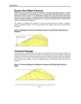
Transient Seepage
Another large class of problems that can be analyzed using SEEP/W is transient seepage. SEEP/W can
account for the drainage of water from soil pores, or water filling soil pores, and the changes in hydraulic
conductivity that occur in a transient seepage flow system. Examples of transient analyses are illustrated
in Figures 1.5 and 1.6. Figure 1.5 shows the migration of the wetting front through and earth dam after
reservoir filling while Figure 1.6 shows the changing position of the phreatic surface after reservoir
drawdown.
Figure 1.5 Transient Wetting Front Migration Through an Earth Dam After Reservoir
Filling
2. GEO-SLOPE Office 5 15
Figure 1.6 Movement of Phreatic Surface in an Earth Dam After Reservoir Drawdown
The SEEP/W capability of accommodating both saturated and unsaturated flow makes it a very powerful
tool for analyzing almost any kind of seepage problem you may encounter.
Features and Capabilities
User Interface
Problem Definition
CAD is an acronym for Computer Aided Drafting. GEO-SLOPE has implemented CAD-like
functionality in SEEP/W using the Microsoft Windows graphical user interface. This means that defining
your problem on the computer is just like drawing it on paper; the screen becomes your "page" and the
mouse becomes your "pen." Once your page size and engineering scale have been specified, the cursor
position is displayed on the screen in engineering coordinates. As you move the mouse, the cursor
position is updated. You can then "draw" your problem on the screen by moving and clicking the mouse.
The following are some of the model definition interface features:
· Display axes, snap to a grid, and zoom.
To facilitate drawing, x and y axes may be placed on the drawing for reference. Using the mouse, axes
may be selected, then moved, resized or deleted. For placing the mouse on precise coordinates, a
background grid may be specified. Using a "snap" option, the mouse coordinates will be set to exact
grid coordinates when the mouse cursor nears a grid point. To view a smaller portion of the drawing, it
is possible to zoom in by using the mouse to drag a rectangle around the area of interest. Zooming out
to a larger scale is also possible.
· Sketch graphics, text and import picture.
Graphics and text features are provided to aid in defining models and to enhance the output of results.
Graphics such as lines, circles and arcs, are useful for sketching the problem domain before defining a
finite element mesh. Text is useful for annotating the drawing to show information such as material
names and properties among other things. A dynamic text feature automatically updates the project
information text on the drawing whenever the project information is changed. This ensures that the
project information shown on the drawing always matches the project settings used in the model.
The import picture feature is useful for displaying graphics from other applications in your drawing.
For example, a cross-section drawing could be imported from a drafting application for use as a
background graphic while defining the problem domain. This feature can also be used to display things
like photographs or a company logo on the drawing. Pictures are imported as a Windows metafile
(WMF), an enhanced metafile (EMF), or a Windows bitmap (BMP).
Using the mouse, individual or groups of graphics and text objects may be selected, then moved,
resized or deleted.
3. 16 SEEP/W
· Graphical finite element mesh generation and editing.
After the problem has been sketched, the problem domain must be discretized into a finite element
mesh. To facilitate this, quadrilateral and/or triangular regions are drawn in the problem domain. Inside
each region, any number of finite elements can automatically be generated. Individual or groups of
nodes and elements may be moved or deleted using the mouse to select and drag these objects. The
figure below shows how a quadrilateral region is interactively meshed with quadrilateral elements.
· Graphical application of soil types and boundary conditions.
Each element in the mesh must be associated with a soil type. This can be accomplished using the
mouse to select individual or groups of elements to which a soil type will be assigned. Boundary
conditions can also be assigned to nodes and edges using the mouse. The figure below shows the
application of a fixed 0.3 m total head boundary condition being applied to node 10.
4. GEO-SLOPE Office 5 17
· Graphical and keyboard editing of functions.
SEEP/W makes extensive use of functions. For example, boundary conditions can be a function of
time, and hydraulic conductivity is a function of pore-water pressure. All these functions can be edited
graphically using the mouse and exact numerical values can be input using the keyboard. The figure
below shows a point on a conductivity function being moved using the mouse.
5. 18 SEEP/W
· Graphical flux section definition.
It is often of interest to compute seepage fluxes across some section of the problem domain. Multiple
flux sections can be drawn through the problem domain using the mouse.
· Graphical initial water table definition.
For transient analyses, initial conditions are required. The fastest way to specify initial conditions is to
draw the water table across the problem domain, which can be done using the mouse.