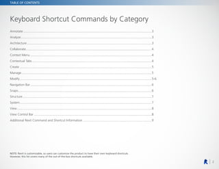
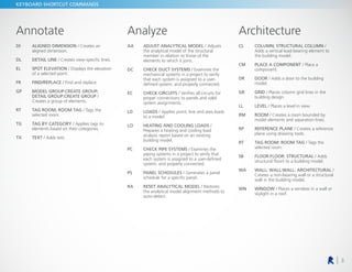
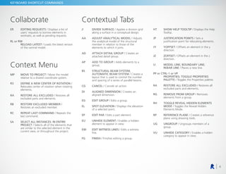
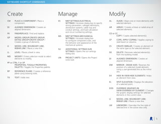
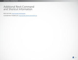
Shortcuts Guide
2
TABLE OF CONTENTS
Keyboard Shortcut Commands by Category
Annotate.................................................................................................................................................3
Analyze....................................................................................................................................................3
Architecture.............................................................................................................................................3
Collaborate..............................................................................................................................................4
Context Menu.........................................................................................................................................4
Contextual Tabs.......................................................................................................................................4
Create.....................................................................................................................................................5
Manage...................................................................................................................................................5
Modify.....................................................................................................................................................5-6
Navigation Bar.........................................................................................................................................6
Snaps.......................................................................................................................................................6
Structure..................................................................................................................................................7
System.....................................................................................................................................................7
View........................................................................................................................................................8
View Control Bar.....................................................................................................................................8
Additional Revit Command and Shortcut Information..............................................................................9
NOTE: Revit is customizable, so users can customize the product to have their own keyboard shortcuts.
However, this list covers many of the out-of-the-box shortcuts available.
3
KEYBOARD SHORTCUT COMMANDS
Annotate
DI	ALIGNED DIMENSION / Creates an
aligned dimension.
DL DETAIL LINE / Creates view-specific lines.
EL	SPOT ELEVATION / Displays the elevation
of a selected point.
FR FIND/REPLACE / Find and replace.
GP	
MODEL GROUP:CREATE GROUP;
DETAIL GROUP:CREATE GROUP /
Creates a group of elements.
RT	
TAG ROOM; ROOM TAG / Tags the
selected room.
TG	
TAG BY CATEGORY / Applies tags to
elements based on their categories.
TX TEXT / Adds text.
Analyze
AA	
ADJUST ANALYTICAL MODEL / Adjusts
the analytical model of the structural
member in relation to those of the
elements to which it joins.
DC	
CHECK DUCT SYSTEMS / Examines the
mechanical systems in a project to verify
that each system is assigned to a user-
defined system, and properly connected.
EC	CHECK CIRCUITS / Verifies all circuits for
proper connections to panels and valid
system assignments.
LD	LOADS / Applies point, line and area loads
to a model.
LO	
HEATING AND COOLING LOADS /
Prepares a heating and cooling load
analysis report based on an existing
building model.
PC	
CHECK PIPE SYSTEMS / Examines the
piping systems in a project to verify that
each system is assigned to a user-defined
system, and properly connected.
PS	PANEL SCHEDULES / Generates a panel
schedule for a specific panel.
RA	
RESET ANALYTICAL MODEL / Restores
the analytical model alignment methods to
auto-detect.
Architecture
CL	
COLUMN; STRUCTURAL COLUMN /
Adds a vertical load-bearing element to
the building model.
CM	
PLACE A COMPONENT / Place a
component.
DR	DOOR / Adds a door to the building
model.
GR	GRID / Places column grid lines in the
building design.
LL LEVEL / Places a level in view.
RM	ROOM / Creates a room bounded by
model elements and separation lines.
RP	REFERENCE PLANE / Creates a reference
plane using drawing tools.
RT	
TAG ROOM; ROOM TAG / Tags the
selected room.
SB	FLOOR:FLOOR: STRUCTURAL / Adds
structural floors to a building model.
WA	
WALL; WALL:WALL: ARCHITECTURAL /
Creates a non-bearing wall or a structural
wall in the building model.
WN	WINDOW / Places a window in a wall or
skylight in a roof.
4
KEYBOARD SHORTCUT COMMANDS
Collaborate
ER	EDITING REQUESTS / Displays a list of
users’ requests to borrow elements in
worksets, as well as pending requests.
RL or RW
	RELOAD LATEST / Loads the latest version
of the central model.
Context Menu
MP	
MOVE TO PROJECT / Move the model
relative to a shared coordinate system.
R3	
DEFINE A NEW CENTER OF ROTATION /
Relocates center of rotation when rotating
elements.
RA	
RESTORE ALL EXCLUDED / Restores all
excluded parts and elements.
RB	
RESTORE EXCLUDED MEMBER /
Restores an excluded member.
RC	
REPEAT LAST COMMAND / Repeats the
last command.
SA	
SELECT ALL INSTANCES: IN ENTIRE
PROJECT / Selects all of the elements that
are similar to the selected element in the
current view, or throughout the project.
Contextual Tabs
//	DIVIDE SURFACE / Applies a division grid
along a surface in a conceptual design.
AA	
ADJUST ANALYTICAL MODEL / Adjusts
the analytical model of the structural
member in relation to those of the
elements to which it joins.
AD	
ATTACH DETAIL GROUP / Creates an
attached detail group.
AP	
ADD TO GROUP / Adds elements to a
group.
BS	
STRUCTURAL BEAM SYSTEM;
AUTOMATIC BEAM SYSTEM / Creates a
layout that is used to control the number
and spacing of a series of parallel beams.
CG CANCEL / Cancels an action.
DI	ALIGNED DIMENSION / Creates an
aligned dimension.
EG EDIT GROUP / Edits a group.
EL	SPOT ELEVATION / Displays the elevation
of a selected point.
EP EDIT PAR / Edits a part element.
EU	UNHIDE ELEMENT / Enables a hidden
element to appear in view.
EW	
EDIT WITNESS LINES / Edits a witness
line.
FG FINISH / Finishes editing a group.
HT	
SHOW HELP TOOLTIP / Displays the Help
Tooltip.
JP	JUSTIFICATION POINTS / Sets a
justification point for relocating elements.
JY	YOFFSET / Offsets an element in the y
direction.
JZ	ZOFFSET / Offsets an element in the z
direction.
LI	
MODEL LINE; BOUNDARY LINE;
REBAR LINE / Places a new line.
PP or CTRL-1 or VP
	
PROPERTIES; TOGGLE PROPERTIES
PALETTE / Toggles the Properties palette.
RA	
RESTORE ALL EXCLUDED / Restores all
excluded parts and elements.
RG	
REMOVE FROM GROUP / Removes
elements from a group.
RH	
TOGGLE REVEAL HIDDEN ELEMENTS
MODE / Toggles the Reveal Hidden
Elements Mode.
RP	REFERENCE PLANE / Creates a reference
plane using drawing tools.
UG	UNGROUP / Ungroups members of a
group.
VU	UNHIDE CATEGORY / Enables a hidden
category to appear in view.
5
KEYBOARD SHORTCUT COMMANDS
Create
CM	
PLACE A COMPONENT / Place a
component.
DI	ALIGNED DIMENSION / Creates an
aligned dimension.
FR FIND/REPLACE / Find and replace.
GP	
MODEL GROUP:CREATE GROUP;
DETAIL GROUP:CREATE GROUP /
Creates a group of elements.
LI	
MODEL LINE; BOUNDARY LINE;
REBAR LINE / Places a new line.
LL LEVEL / Places a level in view.
MD	MODIFY / Enters selection mode to select
elements to modify.
PP or CTRL-1 or VP
	
PROPERTIES; TOGGLE PROPERTIES
PALETTE / Toggles the Properties palette.
RP	REFERENCE PLANE / Creates a reference
plane using drawing tools.
TX TEXT / Adds text.
Manage
ES	MEP SETTINGS:ELECTRICAL
SETTINGS / Accesses dialog box to specify
wiring parameters, voltages definitions,
distribution systems, cable tray and
conduit settings, and load calculation
and circuit numbering settings.
MS	MEP SETTINGS:MECHANICAL
SETTINGS / Accesses dialog box
to configure component sizes, and
the behavior and appearance of the
mechanical systems.
SU	ADDITIONAL SETTINGS:SUN
SETTINGS / Opens the sun settings
dialog box.
UN	PROJECT UNITS / Opens the Project
Units tool.
Modify
AL	ALIGN / Aligns one or more elements with
selected element.
AR	ARRAY / Creates a linear or radial array of
selected elements.
CO or CC
COPY / Copies selected element(s).
CP	
COPE; APPLY COPING / Applies coping to
steel beam or columns.
CS	CREATE SIMILAR / Creates an element of
the same type as the selected element.
DE	DELETE / Removes selected element(s)
from the building model.
DI	ALIGNED DIMENSION / Creates an
aligned dimension.
DM	
MIRROR - DRAW AXIS / Reverses the
position of a selected model element,
using a user-generated line as the mirror
axis.
EH	
HIDE IN VIEW:HIDE ELEMENTS / Hides
an element from view.
EL	SPOT ELEVATION / Displays the elevation
of a selected point.
EOD	
OVERRIDE GRAPHICS IN
VIEW:OVERRIDE BY ELEMENT / Changes
the graphic display settings for selected
elements in the current view.
LI	
MODEL LINE; BOUNDARY LINE;
REBAR LINE / Places a new line.
LW	LINEWORK / Overrides the line style of
selected line in the active view only.
6
KEYBOARD SHORTCUT COMMANDS
Modify
MA	
MATCH TYPE PROPERTIES / Opens the
Match Type tool to convert one or more
elements to match the type assigned to
another element.
MM	
MIRROR - PICK AXIS / Reverses the
position of a selected model element,
using a selected line as the mirror axis.
MV MOVE / Moves a selected element.
OF	OFFSET / Moves a selected model line,
detail line, wall, or beam a specified
distance perpendicular to its length.
PN PIN / Locks a model element in place.
PP or CTRL-1 or VP
	
PROPERTIES; TOGGLE PROPERTIES
PALETTE / Toggles the Properties palette.
PT PAINT / Opens the Paint tool.
RC	COPE:REMOVE COPING / Removes
coping.
RE SCALE / Resizes the selected element.
RO	ROTATE / Rotates selected element
around an axis.
RP	REFERENCE PLANE / Creates a reference
plane using drawing tools.
SF	SPLIT FACE / Divides the face of an
element into regions for application of
different materials.
SL	SPLIT ELEMENT / Cuts an element (such
as a wall or line) at a selected point.
TR	
TRIM/EXTEND TO CORNER / Trims or
extend one or more elements to form a
corner.
UP	UNPIN / Unpins an element that is locked
in position or an element that is driven by
its host system.
VH	
HIDE IN VIEW:HIDE CATEGORY / Hides
an element category from view.
Navigation Bar
32	2D MODE / Navigates the view using only
2D navigation options.
3F	FLY MODE / Simulates flying through a
model.
3O	OBJECT MODE / Navigates and reorients
the view in the direction of the controller
cap.
3W	WALK MODE / Simulates walking
through a model.
ZA	
ZOOM ALL TO FIT / Zooms to fit all in
view.
ZE or ZF or ZX
ZOOM TO FIT / Zooms to fit.
ZO or ZV
	ZOOM OUT(2X) / Zooms out the project
view by 2X.
ZP or ZC
	PREVIOUS PAN/ZOOM / Returns to
previous pan or zoom.
ZR or ZZ
ZOOM IN REGION / Zooms to a region.
ZS ZOOM SHEET SIZE / Zooms to sheet size.
Snaps
PC	
SNAP TO POINT CLOUDS / Snaps to
point cloud.
SC CENTERS / Snaps to center.
SE ENDPOINTS / Snaps to endpoints.
SI INTERSECTIONS / Snaps to intersection.
SM MIDPOINTS / Snaps to midpoint.
SN NEAREST / Snaps to nearest.
SO SNAPS OFF / Turns snaps off.
SP	PERPENDICULAR / Snaps to
perpendicular.
SQ QUADRANTS / Snaps to quadrant.
SR	
SNAP TO REMOTE OBJECTS / Snaps to
objects that are not near the element.
SS	
TURN OVERRIDE OFF / Turns off override
feature.
ST TANGENTS / Snaps to tangent.
SW	
WORK PLANE GRID / Snaps to the work
plane grid.
SX POINTS / Snaps to points.
7
KEYBOARD SHORTCUT COMMANDS
Structure
BM	
STRUCTURAL FRAMING: BEAM / Adds
a load-bearing structural beam element to
the building model.
BR	
STRUCTURAL FRAMING: BRACE / Adds
diagonal members that are connected to
beams and columns.
BS	
STRUCTURAL BEAM SYSTEM;
AUTOMATIC BEAM SYSTEM / Creates a
layout that is used to control the number
and spacing of a series of parallel beams.
CL	
COLUMN; STRUCTURAL COLUMN /
Adds a vertical load-bearing element to
the building model.
CM	
PLACE A COMPONENT / Place a
component.
FT	
STRUCTURAL FOUNDATION: WALL /
Creates a wall foundation for the building
model.
GR	GRID / Places column grid lines in the
building design.
LL LEVEL / Places a level in view.
RN	REINFORCEMENT NUMBERS / Defines or
edits numbering sequences by partition for
rebar and fabric sheets.
RP	REFERENCE PLANE / Creates a reference
plane using drawing tools.
SB	FLOOR:FLOOR: STRUCTURAL / Adds
structural floors to a building model.
WA	
WALL; WALL:WALL: ARCHITECTURAL /
Creates a non-bearing wall or a structural
wall in the building model.
System
AT	AIR TERMINAL / Places a register, grille or
diffuser.
CM	
PLACE A COMPONENT / Place a
component.
CN CONDUIT / Draws a rigid conduit run.
CT CABLE TRAY / Draws a cable tray run.
CV	
CONVERT TO FLEX DUCT / Converts a
section of rigid duct to flexible duct.
DA	DUCT ACCESSORY / Adds duct
accessories, such as dampers, in duct
systems.
DF	DUCT FITTING / Places duct fittings
(elbows, tees, end caps, and so on) in duct
systems.
DT	DUCT / Draws ductwork in the building
model.
EE	ELECTRICAL EQUIPMENT / Places
electrical equipment, such as panels and
switch gear.
EW ARC WIRE / Draws an arced wire run.
FD	FLEX DUCT / Draws flexible ductwork in
the building model.
FP FLEX PIPE / Draws flexible pipes.
LF	LIGHTING FIXTURE / Adds a lighting
fixture element.
ME	MECHANICAL EQUIPMENT / Places
mechanical equipment such as boilers,
furnaces or fans.
NF	CONDUIT FITTING / Places conduit
fittings.
PA PIPE ACCESSORY / Adds pipe accessories.
PF	PIPE FITTING / Draws a pipe fitting in a
piping system.
PI PIPE / Draws rigid piping.
PX	PLUMBING FIXTURE / Places a plumbing
fixture.
RP	REFERENCE PLANE / Creates a reference
plane using drawing tools.
SK SPRINKLER / Places a sprinkler.
TF	
CABLE TRAY FITTING / Places cable tray
fittings.
8
KEYBOARD SHORTCUT COMMANDS
View
FN9	SYSTEM BROWSER / Finds components
that are not assigned to a system.
KS	KEYBOARD SHORTCUTS / Assigns key
sequences to tools.
PP or CTRL-1 or VP
	
PROPERTIES; TOGGLE PROPERTIES
PALETTE / Toggles the Properties palette.
RD	
RENDER IN CLOUD / Renders 3D views
online.
RG	RENDER GALLERY / Enables access
to multiple versions of renderings,
render images as panoramas, change
rendering quality, and apply background
environments to rendered scenes.
RR	RENDER / Creates a photorealistic image
of the building model.
TL	THIN LINES / Displays all lines on the
screen as a single width, regardless of
zoom level.
VG or VV
	VISIBILITY/GRAPHICS / Controls the
visibility and graphic display of model
elements, datum elements, and view-
specific elements for each view in a
project.
WC	CASCADE WINDOWS / Arranges all open
windows in a series in the drawing area.
WT	TILE WINDOWS / See all open views at
the same time.
View Control Bar
CX	
TOGGLE REVEAL CONSTRAINTS
MODE / Toggles the constraints in a view.
GD	
GRAPHIC DISPLAY OPTIONS / Opens the
Graphics dialog box.
HC	HIDE CATEGORY / Hides all selected
categories in the view.
HH	HIDE ELEMENT / Hides an element from
view.
HI	ISOLATE ELEMENT / Isolates selected
elements.
HL	HIDDEN LINE / Displays the image with
all edges and lines drawn except those
obstructed by surfaces.
HR	
RESET TEMPORARY HIDE/ISOLATE /
Restores any temporarily hidden elements
or categories.
IC	ISOLATE CATEGORY / Isolates selected
categories.
RD	
RENDER IN CLOUD / Renders 3D views
online.
RG	RENDER GALLERY / Enables access
to multiple versions of renderings,
render images as panoramas, change
rendering quality, and apply background
environments to rendered scenes.
RH	
TOGGLE REVEAL HIDDEN ELEMENTS
MODE / Toggles the Reveal Hidden
Elements Mode.
RR	RENDER / Creates a photorealistic image
of the building model.
RY	RAY TRACE / Opens Ray Trace visual style,
enablingaphotorealisticrenderingmodethat
allowspanningandzoomingaroundthemodel.
SD	
SHADED WITH EDGES / Applies a shaded
edge.
WF	WIREFRAME / Displays the image of the
model with all edges and lines drawn, but
with no surfaces drawn.
9
ADDITIONAL INFORMATION
Additional Revit Command
and Shortcut Information
REVIT KEYTIPS: http://autode.sk/revitkeytips
CUSTOM REVIT SHORTCUTS: http://autode.sk/revitcustomshortcuts

Revit_Keyboard_Shortcuts_Guide.pdf

  • 1.
  • 2.
    2 TABLE OF CONTENTS KeyboardShortcut Commands by Category Annotate.................................................................................................................................................3 Analyze....................................................................................................................................................3 Architecture.............................................................................................................................................3 Collaborate..............................................................................................................................................4 Context Menu.........................................................................................................................................4 Contextual Tabs.......................................................................................................................................4 Create.....................................................................................................................................................5 Manage...................................................................................................................................................5 Modify.....................................................................................................................................................5-6 Navigation Bar.........................................................................................................................................6 Snaps.......................................................................................................................................................6 Structure..................................................................................................................................................7 System.....................................................................................................................................................7 View........................................................................................................................................................8 View Control Bar.....................................................................................................................................8 Additional Revit Command and Shortcut Information..............................................................................9 NOTE: Revit is customizable, so users can customize the product to have their own keyboard shortcuts. However, this list covers many of the out-of-the-box shortcuts available.
  • 3.
    3 KEYBOARD SHORTCUT COMMANDS Annotate DI ALIGNEDDIMENSION / Creates an aligned dimension. DL DETAIL LINE / Creates view-specific lines. EL SPOT ELEVATION / Displays the elevation of a selected point. FR FIND/REPLACE / Find and replace. GP MODEL GROUP:CREATE GROUP; DETAIL GROUP:CREATE GROUP / Creates a group of elements. RT TAG ROOM; ROOM TAG / Tags the selected room. TG TAG BY CATEGORY / Applies tags to elements based on their categories. TX TEXT / Adds text. Analyze AA ADJUST ANALYTICAL MODEL / Adjusts the analytical model of the structural member in relation to those of the elements to which it joins. DC CHECK DUCT SYSTEMS / Examines the mechanical systems in a project to verify that each system is assigned to a user- defined system, and properly connected. EC CHECK CIRCUITS / Verifies all circuits for proper connections to panels and valid system assignments. LD LOADS / Applies point, line and area loads to a model. LO HEATING AND COOLING LOADS / Prepares a heating and cooling load analysis report based on an existing building model. PC CHECK PIPE SYSTEMS / Examines the piping systems in a project to verify that each system is assigned to a user-defined system, and properly connected. PS PANEL SCHEDULES / Generates a panel schedule for a specific panel. RA RESET ANALYTICAL MODEL / Restores the analytical model alignment methods to auto-detect. Architecture CL COLUMN; STRUCTURAL COLUMN / Adds a vertical load-bearing element to the building model. CM PLACE A COMPONENT / Place a component. DR DOOR / Adds a door to the building model. GR GRID / Places column grid lines in the building design. LL LEVEL / Places a level in view. RM ROOM / Creates a room bounded by model elements and separation lines. RP REFERENCE PLANE / Creates a reference plane using drawing tools. RT TAG ROOM; ROOM TAG / Tags the selected room. SB FLOOR:FLOOR: STRUCTURAL / Adds structural floors to a building model. WA WALL; WALL:WALL: ARCHITECTURAL / Creates a non-bearing wall or a structural wall in the building model. WN WINDOW / Places a window in a wall or skylight in a roof.
  • 4.
    4 KEYBOARD SHORTCUT COMMANDS Collaborate ER EDITINGREQUESTS / Displays a list of users’ requests to borrow elements in worksets, as well as pending requests. RL or RW RELOAD LATEST / Loads the latest version of the central model. Context Menu MP MOVE TO PROJECT / Move the model relative to a shared coordinate system. R3 DEFINE A NEW CENTER OF ROTATION / Relocates center of rotation when rotating elements. RA RESTORE ALL EXCLUDED / Restores all excluded parts and elements. RB RESTORE EXCLUDED MEMBER / Restores an excluded member. RC REPEAT LAST COMMAND / Repeats the last command. SA SELECT ALL INSTANCES: IN ENTIRE PROJECT / Selects all of the elements that are similar to the selected element in the current view, or throughout the project. Contextual Tabs // DIVIDE SURFACE / Applies a division grid along a surface in a conceptual design. AA ADJUST ANALYTICAL MODEL / Adjusts the analytical model of the structural member in relation to those of the elements to which it joins. AD ATTACH DETAIL GROUP / Creates an attached detail group. AP ADD TO GROUP / Adds elements to a group. BS STRUCTURAL BEAM SYSTEM; AUTOMATIC BEAM SYSTEM / Creates a layout that is used to control the number and spacing of a series of parallel beams. CG CANCEL / Cancels an action. DI ALIGNED DIMENSION / Creates an aligned dimension. EG EDIT GROUP / Edits a group. EL SPOT ELEVATION / Displays the elevation of a selected point. EP EDIT PAR / Edits a part element. EU UNHIDE ELEMENT / Enables a hidden element to appear in view. EW EDIT WITNESS LINES / Edits a witness line. FG FINISH / Finishes editing a group. HT SHOW HELP TOOLTIP / Displays the Help Tooltip. JP JUSTIFICATION POINTS / Sets a justification point for relocating elements. JY YOFFSET / Offsets an element in the y direction. JZ ZOFFSET / Offsets an element in the z direction. LI MODEL LINE; BOUNDARY LINE; REBAR LINE / Places a new line. PP or CTRL-1 or VP PROPERTIES; TOGGLE PROPERTIES PALETTE / Toggles the Properties palette. RA RESTORE ALL EXCLUDED / Restores all excluded parts and elements. RG REMOVE FROM GROUP / Removes elements from a group. RH TOGGLE REVEAL HIDDEN ELEMENTS MODE / Toggles the Reveal Hidden Elements Mode. RP REFERENCE PLANE / Creates a reference plane using drawing tools. UG UNGROUP / Ungroups members of a group. VU UNHIDE CATEGORY / Enables a hidden category to appear in view.
  • 5.
    5 KEYBOARD SHORTCUT COMMANDS Create CM PLACEA COMPONENT / Place a component. DI ALIGNED DIMENSION / Creates an aligned dimension. FR FIND/REPLACE / Find and replace. GP MODEL GROUP:CREATE GROUP; DETAIL GROUP:CREATE GROUP / Creates a group of elements. LI MODEL LINE; BOUNDARY LINE; REBAR LINE / Places a new line. LL LEVEL / Places a level in view. MD MODIFY / Enters selection mode to select elements to modify. PP or CTRL-1 or VP PROPERTIES; TOGGLE PROPERTIES PALETTE / Toggles the Properties palette. RP REFERENCE PLANE / Creates a reference plane using drawing tools. TX TEXT / Adds text. Manage ES MEP SETTINGS:ELECTRICAL SETTINGS / Accesses dialog box to specify wiring parameters, voltages definitions, distribution systems, cable tray and conduit settings, and load calculation and circuit numbering settings. MS MEP SETTINGS:MECHANICAL SETTINGS / Accesses dialog box to configure component sizes, and the behavior and appearance of the mechanical systems. SU ADDITIONAL SETTINGS:SUN SETTINGS / Opens the sun settings dialog box. UN PROJECT UNITS / Opens the Project Units tool. Modify AL ALIGN / Aligns one or more elements with selected element. AR ARRAY / Creates a linear or radial array of selected elements. CO or CC COPY / Copies selected element(s). CP COPE; APPLY COPING / Applies coping to steel beam or columns. CS CREATE SIMILAR / Creates an element of the same type as the selected element. DE DELETE / Removes selected element(s) from the building model. DI ALIGNED DIMENSION / Creates an aligned dimension. DM MIRROR - DRAW AXIS / Reverses the position of a selected model element, using a user-generated line as the mirror axis. EH HIDE IN VIEW:HIDE ELEMENTS / Hides an element from view. EL SPOT ELEVATION / Displays the elevation of a selected point. EOD OVERRIDE GRAPHICS IN VIEW:OVERRIDE BY ELEMENT / Changes the graphic display settings for selected elements in the current view. LI MODEL LINE; BOUNDARY LINE; REBAR LINE / Places a new line. LW LINEWORK / Overrides the line style of selected line in the active view only.
  • 6.
    6 KEYBOARD SHORTCUT COMMANDS Modify MA MATCHTYPE PROPERTIES / Opens the Match Type tool to convert one or more elements to match the type assigned to another element. MM MIRROR - PICK AXIS / Reverses the position of a selected model element, using a selected line as the mirror axis. MV MOVE / Moves a selected element. OF OFFSET / Moves a selected model line, detail line, wall, or beam a specified distance perpendicular to its length. PN PIN / Locks a model element in place. PP or CTRL-1 or VP PROPERTIES; TOGGLE PROPERTIES PALETTE / Toggles the Properties palette. PT PAINT / Opens the Paint tool. RC COPE:REMOVE COPING / Removes coping. RE SCALE / Resizes the selected element. RO ROTATE / Rotates selected element around an axis. RP REFERENCE PLANE / Creates a reference plane using drawing tools. SF SPLIT FACE / Divides the face of an element into regions for application of different materials. SL SPLIT ELEMENT / Cuts an element (such as a wall or line) at a selected point. TR TRIM/EXTEND TO CORNER / Trims or extend one or more elements to form a corner. UP UNPIN / Unpins an element that is locked in position or an element that is driven by its host system. VH HIDE IN VIEW:HIDE CATEGORY / Hides an element category from view. Navigation Bar 32 2D MODE / Navigates the view using only 2D navigation options. 3F FLY MODE / Simulates flying through a model. 3O OBJECT MODE / Navigates and reorients the view in the direction of the controller cap. 3W WALK MODE / Simulates walking through a model. ZA ZOOM ALL TO FIT / Zooms to fit all in view. ZE or ZF or ZX ZOOM TO FIT / Zooms to fit. ZO or ZV ZOOM OUT(2X) / Zooms out the project view by 2X. ZP or ZC PREVIOUS PAN/ZOOM / Returns to previous pan or zoom. ZR or ZZ ZOOM IN REGION / Zooms to a region. ZS ZOOM SHEET SIZE / Zooms to sheet size. Snaps PC SNAP TO POINT CLOUDS / Snaps to point cloud. SC CENTERS / Snaps to center. SE ENDPOINTS / Snaps to endpoints. SI INTERSECTIONS / Snaps to intersection. SM MIDPOINTS / Snaps to midpoint. SN NEAREST / Snaps to nearest. SO SNAPS OFF / Turns snaps off. SP PERPENDICULAR / Snaps to perpendicular. SQ QUADRANTS / Snaps to quadrant. SR SNAP TO REMOTE OBJECTS / Snaps to objects that are not near the element. SS TURN OVERRIDE OFF / Turns off override feature. ST TANGENTS / Snaps to tangent. SW WORK PLANE GRID / Snaps to the work plane grid. SX POINTS / Snaps to points.
  • 7.
    7 KEYBOARD SHORTCUT COMMANDS Structure BM STRUCTURALFRAMING: BEAM / Adds a load-bearing structural beam element to the building model. BR STRUCTURAL FRAMING: BRACE / Adds diagonal members that are connected to beams and columns. BS STRUCTURAL BEAM SYSTEM; AUTOMATIC BEAM SYSTEM / Creates a layout that is used to control the number and spacing of a series of parallel beams. CL COLUMN; STRUCTURAL COLUMN / Adds a vertical load-bearing element to the building model. CM PLACE A COMPONENT / Place a component. FT STRUCTURAL FOUNDATION: WALL / Creates a wall foundation for the building model. GR GRID / Places column grid lines in the building design. LL LEVEL / Places a level in view. RN REINFORCEMENT NUMBERS / Defines or edits numbering sequences by partition for rebar and fabric sheets. RP REFERENCE PLANE / Creates a reference plane using drawing tools. SB FLOOR:FLOOR: STRUCTURAL / Adds structural floors to a building model. WA WALL; WALL:WALL: ARCHITECTURAL / Creates a non-bearing wall or a structural wall in the building model. System AT AIR TERMINAL / Places a register, grille or diffuser. CM PLACE A COMPONENT / Place a component. CN CONDUIT / Draws a rigid conduit run. CT CABLE TRAY / Draws a cable tray run. CV CONVERT TO FLEX DUCT / Converts a section of rigid duct to flexible duct. DA DUCT ACCESSORY / Adds duct accessories, such as dampers, in duct systems. DF DUCT FITTING / Places duct fittings (elbows, tees, end caps, and so on) in duct systems. DT DUCT / Draws ductwork in the building model. EE ELECTRICAL EQUIPMENT / Places electrical equipment, such as panels and switch gear. EW ARC WIRE / Draws an arced wire run. FD FLEX DUCT / Draws flexible ductwork in the building model. FP FLEX PIPE / Draws flexible pipes. LF LIGHTING FIXTURE / Adds a lighting fixture element. ME MECHANICAL EQUIPMENT / Places mechanical equipment such as boilers, furnaces or fans. NF CONDUIT FITTING / Places conduit fittings. PA PIPE ACCESSORY / Adds pipe accessories. PF PIPE FITTING / Draws a pipe fitting in a piping system. PI PIPE / Draws rigid piping. PX PLUMBING FIXTURE / Places a plumbing fixture. RP REFERENCE PLANE / Creates a reference plane using drawing tools. SK SPRINKLER / Places a sprinkler. TF CABLE TRAY FITTING / Places cable tray fittings.
  • 8.
    8 KEYBOARD SHORTCUT COMMANDS View FN9 SYSTEMBROWSER / Finds components that are not assigned to a system. KS KEYBOARD SHORTCUTS / Assigns key sequences to tools. PP or CTRL-1 or VP PROPERTIES; TOGGLE PROPERTIES PALETTE / Toggles the Properties palette. RD RENDER IN CLOUD / Renders 3D views online. RG RENDER GALLERY / Enables access to multiple versions of renderings, render images as panoramas, change rendering quality, and apply background environments to rendered scenes. RR RENDER / Creates a photorealistic image of the building model. TL THIN LINES / Displays all lines on the screen as a single width, regardless of zoom level. VG or VV VISIBILITY/GRAPHICS / Controls the visibility and graphic display of model elements, datum elements, and view- specific elements for each view in a project. WC CASCADE WINDOWS / Arranges all open windows in a series in the drawing area. WT TILE WINDOWS / See all open views at the same time. View Control Bar CX TOGGLE REVEAL CONSTRAINTS MODE / Toggles the constraints in a view. GD GRAPHIC DISPLAY OPTIONS / Opens the Graphics dialog box. HC HIDE CATEGORY / Hides all selected categories in the view. HH HIDE ELEMENT / Hides an element from view. HI ISOLATE ELEMENT / Isolates selected elements. HL HIDDEN LINE / Displays the image with all edges and lines drawn except those obstructed by surfaces. HR RESET TEMPORARY HIDE/ISOLATE / Restores any temporarily hidden elements or categories. IC ISOLATE CATEGORY / Isolates selected categories. RD RENDER IN CLOUD / Renders 3D views online. RG RENDER GALLERY / Enables access to multiple versions of renderings, render images as panoramas, change rendering quality, and apply background environments to rendered scenes. RH TOGGLE REVEAL HIDDEN ELEMENTS MODE / Toggles the Reveal Hidden Elements Mode. RR RENDER / Creates a photorealistic image of the building model. RY RAY TRACE / Opens Ray Trace visual style, enablingaphotorealisticrenderingmodethat allowspanningandzoomingaroundthemodel. SD SHADED WITH EDGES / Applies a shaded edge. WF WIREFRAME / Displays the image of the model with all edges and lines drawn, but with no surfaces drawn.
  • 9.
    9 ADDITIONAL INFORMATION Additional RevitCommand and Shortcut Information REVIT KEYTIPS: http://autode.sk/revitkeytips CUSTOM REVIT SHORTCUTS: http://autode.sk/revitcustomshortcuts