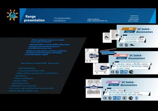
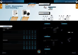
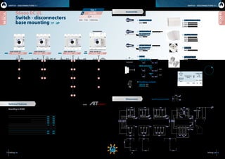
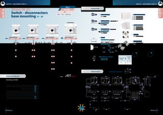
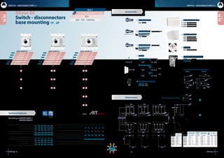
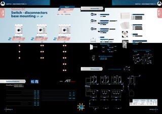
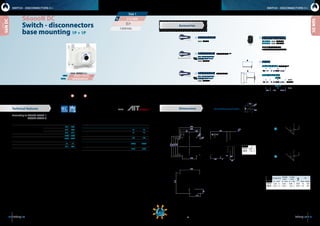
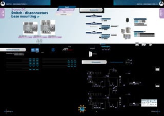
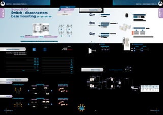
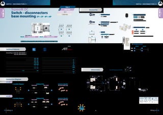
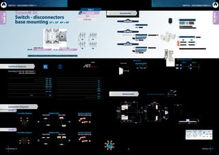
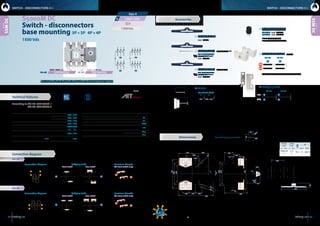
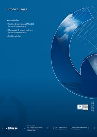
DC Switch - disconnectors
Applications:
Solar Inverters
Combiner boxes
Battery chargers
Main features of our DC Switch - disconnectors
Design according to:
UL98B  UL508i & IEC/EN 60947-1&3
For photovoltaic
installations
Range
presentation
ZFV   DC Switch -
disconnectorsPage 4-5
16  25  32  40  55 A  600 VdcUL
16  25  32  40  55 A  1000 VdcIEC
Ratings
S6000   DC Switch -
disconnectorsPage 6-15
250  400 A  1000 VdcUL
125  160  200  250  315  400  500  630 A  1000Vdc
315  400 A  1500Vdc
IEC
Ratings
SIMPLIFIED
QUICK CONNECT
S5000   DC Switch -
disconnectorsPage 16-33
600  800 A  1000 VdcUL
850  1250  1800  2000  2500  3150 A  1000 VdcIEC
200  315  400  500  600  800  1000  1250 A  1500Vdc
Ratings
200  400 A  1000 Vdc
Load break switching
Non polarised switch-disconnectors
Models with direct, external and door interlock handles
Optimized size
Different wiring diagrams
Less power losses
Optimized connections
Accessories for terminal protection
Save on labor costs in combiner box and inverter assembly
Reduction of the total installation space
A disconnecting device is required to be located
at some point in the PV circuit
Load break switches are recommended for safety purposes,
allowing personnel to work on the equipment
without the risk of electrical shock
Switches also allow operators to shut down zones/sections
of the field for maintenance purposes, while keeping
the rest of the PV plant energized
8  16  20  30  40 A  1500 Vdc
54 dimensions:   inches   millimeters
16  25  32  40  55AZFV
ZFV16SMAH1A4O
ZFV40SMAH1A4O
ZFV25SMAH1A4O
ZFV55SMAH1A4O
25A
55A
16A
40A
25A
16A
55A
40A
ZFV25VZVH4A4O
ZFV55VZVH4A4O
ZFV16VZVH4A4O
ZFV40VZVH4A4O
ZFV32SMAH1A4O32A 32A ZFV32VZVH4A4O
CODE 2P CODE 2P
Technical features
Switch - disconnectors
base mounting 2P
Size 00-0
ZFV
series
ZFV16 ZFV25 ZFV32 ZFV40 ZFV55
Ampere-Rating“General use”
2 Poles in series UL
600 Vdc A 16 20 25 40 55
1000 Vdc A - - - 16 20
4 Poles in series UL
600 Vdc A 16 25 32 40 55
1000 Vdc A - - - 40 55
Fuse size (RK5) 5 kA / 600 V Industrial Control Switch A 40 60 80 - -
Fuse size (RK5) 5 kA / 1000 V Industrial Control Switch A - - - 90 125
Maximum cable cross sections (included jumper)
Solid or stranded AWG 12 - 10 12 - 10 12 - 10 16 - 10 16 - 10
Flexible AWG 12 - 6 12 - 6 12 - 6 14 - 4 14 - 4
Flexible (+ multicore cable end) AWG 12 - 6 12 - 6 12 - 6 - - - -
Size of terminal screw M4 Pz2 M4 Pz2 M4 Pz2 M5Pz2 M5Pz2
Tightening torque lb.inch 9 - 16 9 - 16 9 - 16 22 - 25 22 - 25
ZFV16 ZFV25 ZFV32 ZFV40 ZFV55
Rated operational current
Ie DC21B 2 Poles in series IEC
1000 Vdc A 9 11 13 20 25
1500 Vdc A 3 4 5 6 8
Ie DC21B 4 Poles in series IEC
1000 Vdc A 16 25 32 40 55
1500 Vdc A 16 20 23 30 40
Rated conditional short-circuit current kAeff 5 5 5 10 10
Max. fuse size gL (gG) A 40 63 80 125 160
Maximum cable cross sections (included jumper)
Solid or stranded mm2
4 - 16 4 - 16 4 - 16 2,5 - 25 2,5 - 25
Flexible mm2
4 - 10 4 - 10 4 - 10 4 - 16 4 - 16
Flexible (+ multicore cable end) mm2
4 - 10 4 - 10 4 - 10 2,5 - 16 2,5 - 16
Size of terminal screw M4 Pz2 M4 Pz2 M4 Pz2 M5Pz2 M5Pz2
Tightening torque Nm 1,7 - 1,8 1,7 - 1,8 1,7 - 1,8 2,5 - 2,8 2,5 - 2,8
Dimensions
ZFV16-32
ZFV40-55
ZFV16-32
P
max = 5.9  150
min = 3.5  89
P
max = 7.6  194
min = 4.06  103
Panel drilling handle
ZFV
series
2.36 60
3.7896
3.3585
3.1580
1.57 40
5.91  150
0.04-0.2
1-5
0.16
4
P
1.26
32
2.36
60
0.16
4
5.24  133
2.95
75
4.45
113
0.04-0.2
1-5
0.16
4
2.83
72
P
2.36 60
3.7896
3.3585
1.7745
1.57 40
ZFV-40-55
2.56
65
1.26
32
2.95
75
0.16
4
1.7745
4.45113
4.06103
2.83 72
ø0.2
ø5
2.36 60
1.42  362.52  64
0.13 3,2+0.01
-0.0
+0,2
-0,0
0.95+0.02
-0.0
0.89+0.01
-0.01
22,5+0,2
-0,2
24,1+0,4
-0,0
SWITCH - DISCONNECTORS O-I SWITCH - DISCONNECTORS O-I
According to IEC / EN 60947-3
UL508i
UL508i
IEC / EN 60947-3
*(c1)
*(c1)
Other configurations are available on request
Other lengths (shafts) are available
on request
Other lengths (shafts) are available
on request
Accessories
	Insulated bridging links
	 CODE ZFV-B1  16-32 A
ZFV-B2  40-55 A
	Used to serial contacts
600 - 1000 - 1500 Vdc
E362647
76 dimensions:   inches   millimeters
2 1
2’ 1’
1’1
1’1
1’
1
2’ 1’1
2
1’2’2
1
1 1’ 2’2
2 2’
1’1
2 1
1’2’
2 1
1’2’
1’1
1 1’2
2’
1’
1
2’
1 1’ 2
1 1’ 2’2
1 1’
2’2
1’1
1’2’
2 1
2’ 1’
12
S6-0250 _ _ S00L S6-0250 _ _ S00L S6-0250 _ _ S00L S6-0200 _ _ S00L
2L 2G 2A
2J 2B
2X
1S 2E
1M
2H 2C
2K 2D
2Y
1U 2F
1Q
1V
1W
250A 250A 250A 200A
250  200A
7/8-14 UNF
TORQUE
500 lbfxin / 56 Nxm
10-32 UNF
TORQUE
26,55 lbfxin / 3 Nxm
L
P
5.51140
4.92
125
4,53
115
2x
1.10
28
1.57
40
ø0.22
ø5,5
S6DC UL
S6DC UL
1’1
1’1
1’1
1A
1B
1C
1D
Switch - disconnectors
base mounting 1P - 2P
S6000 DC UL
CODE - 500 Vdc  CODE - 750 Vdc  CODE - 1000 Vdc  CODE - 1000 Vdc 
FUSIBLE SWITCH
250 A
Conforms to UL98B. Minus 20 to +50ºC. PV disconnects switch. Location Category B
1000 Vdc 250 A  Torque: 159 lbf·in. Short circuit rating: 10 kA
Suitable for Use in PV Systems in accordance with Article 690 of the NEC
IEC-60947-3  Uimp 12 kV  DC21B - 1000 Vdc - 250 A  Ui 1500 Vdc  Ith 250 A
200 A
Conforms to UL98B. Minus -20 to +50ºC. Location Category B
1000 Vdc 200 A PV disconnect Switch. Short circuit rating: 10 kA
Continuous load current not to exceed 80% of the rating of fuses employed
in other than motor circuits
IEC-60947-3  Uimp 12 kV  DC21B - 1000 Vdc - 200 A  Ui 1500 Vdc  Ith 200 A
Accessories
Dimensions
 250 200
Rated thermal current Ith -20ºC to +50ºC  A 250 200
Ampere - Rating Code 500 Vdc A 250 200
Code 750 Vdc A 250 200
Code 1000 Vdc A 250 200
Rated short-circuit current Icc kA 10 10
Maximum weight Consult according to code
Wiring capacity
Minimum connection wire range/AWG MCM 350 350
Maximum connection wire range/AWG MCM 400 400
500 - 750 - 1000 Vdc
According to UL98B
3/0
85 mm2
min
-
400 kcmil
240 mm2
max
Temperature
rating
Copper wire
only
M +5%
-10%
Nxm lbfxin
75 ºC M10 18 159
Size 1
SWITCH - DISCONNECTORS O-I SWITCH - DISCONNECTORS O-I
series
series
	Terminal lug
	 CODE  DR-TL11 (2 units)
	(Using phase barriers DR-SF_ _
to maintain the required clerance
	Phase barriers
	CODE  DR-SF11 (1 unit)
	CODE  DR-SF12 (2 units)
	CODE  DR-SF13 (3 units)
	Terminal shrouds
	CODE  DR-CU11 (1 unit)
	 CODE  DR-CU12 (1 unit)
	CODE  DR-CU13 (1 unit)
	Spacers
	 CODE  DR-EL11 (4 units)
	Direct handle
	 CODE DS-SI11
	Panel handle  without shaft
	IP65  UL50E/NEMA 250
	 Types: 1, 3R, 4, 4X y 12
	 CODE DS-SA14
	Panel handle  shaft included *(e1)
	IP65  UL50E/NEMA 250
	 Types: 1, 3R, 4, 4X y 12
	 CODE DS-SA11
	Shafts
Standard shaft included *(e1)
L P
8.94  227 4.06... 10.1  103... 256
Shaft extensions
Type 1
L P CODE
14.8  375 4.06... 16.3  103... 415 DS-EP14
Type 2
L P CODE
21.1  375 4.06... 22.7  103... 576 DS-EP15
Panel drilling for panel handle
	Auxiliary contacts
	 1NA+1NC  CODE D5LAU01
	2NA+2NC  CODE D5LAU02
	 Ie = 16 A (resistive loads)
	 4 A (inductive loads) at 250 Vac.
Use with Class J
PV fuses up to 200A
16.3413
4.417112,2
ø0.28ø7,14
3.896.5
8.85 225
6.69 170
4.37 111
3.35 85
8.43 214
1.97
50
1.97
50
1.97
50
ø0.49ø12,5
ø0.22
ø5,5
ø0.55
ø14
3.86 98 4.21 107
9.25233
5.9150
1.04
26,5
0.16
4
max. 6.53 166
min.0.52 13
5.13130
0,39
10
3.78
96
5.71 145
2.28
58
67
2.64
0.98
25
5.28
134
ø0.49
ø12,5
ø0.22
ø5,5
ø0.55
ø14
5.13130
16.3413
8.54217
7.6193
5.9150
1.97
50
1 1’
6.49
165
4,53
115
8.07
205
4,53
115
7.28 185
2.28
58
7.24
184
4.21
107
1.97
50
1.97
50
ø0.49
ø12,5
ø0.22
ø5,5
ø0.55
ø14
0.98
25
8.85 225
3.86
98
4.21
107
8.43
214
7.34
183,5
1.97
50
1.97
50
1.97
50
ø0.49
ø12,5
ø0.22
ø5,5
ø0.55
ø14
0.98
25
ø1.34
ø34
0.98
25
Technical features tests:
98 dimensions:   inches   millimeters
S6-0400 _ _ S00L S6-0400 _ _ S00L S6-0400 _ _ S00L400A 400A 400A
400  400A
2 AWG
35 mm2
min
-
600 kcmil
300 mm2
max
Lug Bolt
7/8-14 UNF
-
TORQUE
500 lbfxin
56 Nxm
L
P
2x
191
7.52
6.1
155
5,63
143
7.13 181
6.7
169,5
3.58 91
1.38
35
ø0.49ø12,5
ø0.26
ø6,5
ø0.62ø16
3.54 90
20.73526
10.79274
9.57243
7.52191
6.5165
2.56
65
6 AWG
16 mm2
min
-
350 kcmil
185 mm2
max
Lug Bolt
11/16-16 UNF
-
TORQUE
375 lbfxin
42 Nxm
2x
2x
S6DC UL
S6DC UL
Switch - disconnectors
base mounting 1P - 2P
S6000 DC UL
CODE - 500 Vdc  CODE - 750 Vdc  CODE - 1000 Vdc 
series
500 - 750 - 1000 Vdc
According to UL98B
Size 2
Temperature
rating
Copper wire
only
M +5%
-10%
Nxm lbfxin
75 ºC M10 24 212
Accessories
Dimensions
 
Rated thermal current Ith -20ºC to +50ºC  A 400
Rated operational current Ie Code 500 Vdc A 400
Code 750 Vdc A 400
Code 1000 Vdc A 400
Rated short-circuit current Icc kA 10
Maximum weight Consult according to code
Wiring capacity
Minimum connection wire range/AWG MCM 300
Maximum connection wire range/AWG MCM 350
SWITCH - DISCONNECTORS O-I SWITCH - DISCONNECTORS O-I
series
series
	Terminal lug
	 CODE  DR-TL21 (2 units)
	 CODE  DR-TL22 (2 units)
	(Using phase barriers DR-SF_ _
to maintain the required clerance
	Phase barriers
	CODE  DR-SF21 (1 unit)
	CODE  DR-SF22 (2 units)
	CODE  DR-SF23 (3 units)
	Terminal shrouds
	CODE  DR-CU21 (1 unit)
	 CODE  DR-CU22 (1 unit)
	CODE  DR-CU23 (1 unit)
	Spacers
	 CODE  DR-EL21 (4 units)
	Direct handle
	 CODE DS-LI21
	Panel handle  without shaft
	IP65  UL50E/NEMA 250
	 Types: 1, 3R, 4, 4X y 12
	 CODE DS-LA24
	Panel handle  shaft included *(e1)
	IP65  UL50E/NEMA 250
	 Types: 1, 3R, 4, 4X y 12
	 CODE DS-LA21
Panel drilling for panel handle
	Auxiliary contacts
	 1NA+1NC  CODE D5LAU01
	2NA+2NC  CODE D5LAU02
	 Ie = 16 A (resistive loads)
	 4 A (inductive loads) at 250 Vac.
S6-0400 _ _ S00L400A
CODE - 1000 Vdc 
9.29 236
8.8
222,5
3.58
91
5.71
145
2.56
65
2.56
65
1.38
35
ø0.49ø12,5
ø0.26
ø6,5
ø0.62ø16
232,5
9,15
11.3 286
11
279,5
5.55 141 5.71 145
2.56
65
1.38
35
ø0.49ø12,5
ø0.26
ø6,5
ø0.62ø16
8.28
210
5,63
143
10.2
260
5,63
143
2 1
2’ 1’
1’1
1’1
1’
1
2’ 1’1
2
1’2’2
1
1 1’ 2’2
2 2’
1’1
2 1
1’2’
2 1
1’2’
1’1
1 1’2
2’
1’
1
2’
1 1’ 2
1 1’ 2’2
1 1’
2’2
1’1
1’2’
2 1
2’ 1’
12
2L 2G 2A
2J 2B
2X
1S 2E
1M
2H 2C
2K 2D
2Y
1U 2F
1Q
1V
1W
1’1
1’1
1’1
1A
1B
1C
1D
1 1’
DR-TL21 DR-TL22
	Shafts
Standard shaft included *(e1)
L P
7.68  195 5.28... 9.45  134... 240
Shaft extensions
Type 1
L P CODE
13.6  345 5.28... 15.7  134... 400 DS-EP23
Type 2
L P CODE
21.1  535 5.28... 22  134... 560 DS-EP24
1.10
28
1.57
40
ø0.22
ø5,5
ø1.34
ø34
20.73526,5
11.3 286
5.55 141 5.71 145
8.66 220
5.24 133
3.94 100
2.56
65
0.26
6,5
ø0.62
16
ø0.4ø10,3
2.56
65
2.56
65
11
279,5
ø0.49
ø12.5
11.85301
5.64143,354.783121,5
7.52191
1.38
35
max. 4.69 119
min. 0.51 13
6.5165
5.18 131,5
1.59
40,4
0.2
5
0,39
10
Technical features tests:
Use with Class J
PV fuses up to 400A
400 A
Conforms to UL98B. Minus 20 to +50ºC. PV disconnects switch. Location Category B
1000 Vdc 400 A Torque: 212 lbf·in. Short circuit rating: 10 kA
Suitable for Use in PV Systems in accordance with Article 690 of the NEC
IEC-60947-3 Uimp 12 kV DC21B - 1000 Vdc - 400 A Ui 1500 Vdc Ith 400 A
400 A
Conforms to UL98B. Minus -20 to +50ºC. Location Category B
1000 Vdc 400 A PV disconnect Switch. Short circuit rating: 10 kA
Continuous load current not to exceed 80% of the rating of fuses employed
in other than motor circuits
IEC-60947-3  Uimp 12 kV  DC21B - 1000 Vdc - 400 A  Ui 1500 Vdc  Ith 400 A
FUSIBLE SWITCH
2.56
65
2.56
65
1110 dimensions:   inches   millimeters
L
P
1
2
S6000 DC
1 1’ 2’2
1 1’ 2’2
1 1’
2’2
2 2’
1’1
2L 2G 2A
2J 2B
2X
1S 2E
1M
2H 2C
2K 2D
2Y
1U 2F
1Q
1V
1W
2 1
2’ 1’
2 1
1’2’
2 1
1’2’
1 1’2
2’
1’1
1’1
1’1
1’1
1’
1 1’
1
2’ 1’1
2
1’2’2
1
2’
1 1’ 2
1’2’
2 1
2’ 1’
12
500 - 750 - 1000 Vdc
J
in - mm
125 A 0.98 25
160 A 0.98 25
200 A 0.98 25
250 A 0.98 25
315 A 0.98 25
400 A 1.18  30 *(5)
S6-0125 _ _ S0
S6-0250 _ _ S0
S6-0160 _ _ S0
S6-0315 _ _ S0
S6-0200 _ _ S0
S6-0400 _ _ D0
S6-0125 _ _ S0
S6-0250 _ _ S0
S6-0160 _ _ S0
S6-0315 _ _ S0
S6-0200 _ _ S0
S6-0400 _ _ D0
S6-0125 _ _ S0
S6-0250 _ _ S0
S6-0160 _ _ S0
S6-0315 _ _ S0
S6-0200 _ _ S0
S6-0400 _ _ D0
160A 160A 160A
315A 315A 315A
200A 200A 200A
400A 400A 400A
125A 125A 125A
250A 250A 250A
125  160  200  250  315  400A
ø0.77
ø19,5
1.1
28
1.6
40
2.6
65
ø0.22
ø5,5
ø1.3ø34
3.6  92
= =
1.6
40
1.1
28
ø0.22ø5,5
ø1.3
ø34
3.6 92
==
ø0.77
ø19,5
S max (Cu)
H max
(Cu)
L max (Cu) M
in - mm2
in - mm in - mm Nxm lbfxin
125 A 3.74  95 0.20  5 0.98  25 M10 18 159
160 A 3.74  95 0.20  5 0.98  25 M10 18 159
200 A 4.72  120 0.28  7 0.98  25 M10 18 159
250 A 5.91  150 0.28  7 0.98  25 M10 18 159
315 A 7.28  185 0.28  7 0.98  25 M10 18 159
400 A 9.45  240 *(5)
0.28  7 1.38  35 *(5)
M10 18 159
S6DC
S6DC
Switch - disconnectors
base mounting 1P - 2P
S6000 DC
Size 1
CODE - 500 Vdc  CODE - 750 Vdc  CODE - 1000 Vdc 
tests:
*(1)
Other voltages and / or utilization categories. Please consult
*(2)
Without limiting protective device (short-circuit maintained 50... 200 ms.)
*(3)
With limiting protective device which set a limit to peak value short-circuit making
capacity and maximum power dissipation
*(4)
Please consult us for more operations
125 160 200 250 315 400
Short - circuit behaviour
Rated short-circuit making
capacity *(2)
Icm kA (peak) 10 10 10 10 10 10
Rated short-time withstand
current (1sec)
Icw kA rms 10 10 10 10 10 10
Conditional short - circuit current *(3)
kA rms 100 100 100 100 100 100
Mechanical features
Minimun number of mechanical
operations *(4)
Cycles 200002000020000200002000020000
Maximum weight Consult according to code
Accessories
series
Dimensions
*(5) 
Using phase barriers DR-SF_ _   to maintain the required clerance .
125 160 200 250 315 400
Rated thermal
current
in ambient at
RH 60%
Ith 40º C A 125 160 200 250 315 400
50º C A 125 160 200 250 315 400
60º C A 125 160 200 250 315 315
Rated insulation voltage Ui (DC) V 1500 1500 1500 1500 1500 1500
Rated dielectric strength 50 Hz.,
1 min.
V 5000 5000 5000 5000 5000 5000
Rated impulse withstand voltage Uimp kV 12 12 12 12 12 12
Rated
operational
current *(1)
Ie
Code 500 Vdc
DC21B
A 125 160 200 250 315 400
Code 750 Vdc A 125 160 200 250 315 400
Code 1000 Vdc A 125 160 200 250 315 400
500 - 750 - 1000 Vdc
According to IEC / EN 60947-1
IEC / EN 60947-3
SWITCH - DISCONNECTORS O-I SWITCH - DISCONNECTORS O-I
series
series
	Safety key lock device
	 Simple	 CODE DS-CA11
	Double	CODE DS-CE11
	For external handle, lock the handle by means of a key in
position“OFF”(under request, in“ON”), the key can only be
removed with the handle locked
Simple Double
Panel drilling for handle and keylock device
	Phase barriers
	CODE  DR-SF11 (1 unit)
	CODE  DR-SF12 (2 units)
	CODE  DR-SF13 (3 units)
	Terminal shrouds
	CODE  DR-CU11 (1 unit)
	 CODE  DR-CU12 (1 unit)
	CODE  DR-CU13 (1 unit)
	Spacers
	 CODE  DR-EL11 (4 units)
	Direct handle
	 CODE DS-SI11
	Panel handle  without shaft
	IP65  UL50E/NEMA 250
	 Types: 1, 3R, 4, 4X y 12
	 CODE DS-SA14
	Panel handle  shaft included *(e1)
	IP65  UL50E/NEMA 250
	 Types: 1, 3R, 4, 4X y 12
	 CODE DS-SA11
	Auxiliary contacts
	 1NA+1NC  CODE D5LAU01
	2NA+2NC  CODE D5LAU02
	 Ie = 16 A (resistive loads)
	 4 A (inductive loads) at 250 Vac.
Panel drilling for panel handle
consult
5.51140
4.92
125
4,53
115
1.04
26,5
0.16
4
max. 6.53 166
min.0.52 13
5.13130
0,39
10
3.78
96
5.71 145
2.28
58
67
2.64
J
5.28
134
ø0.49
ø12,5
ø0.22
ø5,5
ø0.55
ø14
5.13130
16.3413
8.54217
7.6193
5.9150
1.97
50
6.49
165
4,53
115
8.07
205
4,53
115
7.28 185
2.28
58
7.24
184
4.21
107
1.97
50
1.97
50
ø0.49
ø12,5
ø0.22
ø5,5
ø0.55
ø14
J
8.85 225
3.86
98
4.21
107
8.43
214
7.34
183,5
1.97
50
1.97
50
1.97
50
ø0.49
ø12,5
ø0.22
ø5,5
ø0.55
ø14
J
1.10
28
1.57
40
ø0.22
ø5,5
ø1.34
ø34
	Shafts
Standard shaft included *(e1)
L P
8.94  227 4.06... 10.1  103... 256
Shaft extensions
Type 1
L P CODE
14.8  375 4.06... 16.3  103... 415 DS-EP14
Type 2
L P CODE
21.1  536 4.06... 22.7  103... 576 DS-EP15
Technical features
1312 dimensions:   inches   millimeters
*(d1)
*(d1)
1 1’ 2’2
1 1’ 2’2
1 1’
2’2
2 2’
1’1
2L 2G 2A
2J 2B
2X
1S 2E
1M
2H 2C
2K 2D
2Y
1U 2F
1Q
1V
1W
2 1
2’ 1’
2 1
1’2’
2 1
1’2’
1 1’2
2’
1’1
1’1
1’1
1’1
1’
1 1’
1
2’ 1’1
2
1’2’2
1
2’
1 1’ 2
1’2’
2 1
2’ 1’
12
L
P
500  630A
S6-0500 _ _ S0
S6-0630 _ _ S0 S6-0630 _ _ S0
S6-0500 _ _ S0
630A
500A
630A
500A
630A
500A
S6-0630 _ _ S0
S6-0500 _ _ S0
500 - 750 - 1000 Vdc
S max (Cu) H max (Cu)
L max
(Cu)
M
in - mm2
in - mm in - mm Nxm lbfxin
500 A 0.08x5.91  2x150 0.24  6 1.57  40 M10 24 212
630 A 0.08x7.28  2x185 0.08x0.20  2x5 1.57  40 M10 24 212
S6DC
S6DC
Switch - disconnectors
base mounting 1P - 2P
S6000 DC
tests:
According to IEC / EN 60947-1
IEC / EN 60947-3
Size 2
500 630
Rated thermal current
in ambient at
RH 60%
Ith 40º C A 500 630
50º C A 500 630
60º C A 500 630
Rated insulation voltage
(DC)
Ui
V 1500 1500
Rated dielectric strength 50 Hz., 1 min. V 8000 8000
Rated impulse withstand
voltage
Uimp
kV 12 12
Rated operational current *(1)
Ie Code 500 Vdc
DC21B
A 500 630
Code 750 Vdc A 500 630
Code 1000 Vdc A 500 630
*(1)
Other voltages and / or utilization categories. Please consult
*(2)
Without limiting protective device (short-circuit maintained 50... 200 ms.)
*(3)
With limiting protective device which set a limit to peak value short-circuit making
capacity and maximum power dissipation
*(4)
Please consult us for more operations
500 630
Short - circuit behaviour
Rated short-circuit making capacity *(2)
Icm kA (peak) 10 10
Rated short-time withstand current (1sec) Icw kA rms 10 10
Conditional short - circuit current *(3)
kA rms 100 100
Mechanical features
Minimun number of mechanical operations *(4)
Cycles 10000 10000
Maximum weight Consult according to code
CODE - 500 Vdc  CODE - 1000 Vdc CODE - 750 Vdc 
Accessories
Dimensions
SWITCH - DISCONNECTORS O-I SWITCH - DISCONNECTORS O-I
series
series
	Safety key lock device
	 Simple	 CODE DS-CB21
	Double	CODE DS-CF21
	For external handle, lock the handle by means of a key in
position“OFF”(under request, in“ON”), the key can only be
removed with the handle locked
Simple Double
Panel drilling for handle and keylock device
	Phase barriers
	CODE  DR-SF21 (1 unit)
	CODE  DR-SF22 (2 units)
	CODE  DR-SF23 (3 units)
	Terminal shrouds
	CODE  DR-CU21 (1 unit)
	 CODE  DR-CU22 (1 unit)
	CODE  DR-CU23 (1 unit)
	Spacers
	 CODE  DR-EL21 (4 units)
	Direct handle
	 CODE DS-LI21
	Panel handle  without shaft
	IP65  UL50E/NEMA 250
	 Types: 1, 3R, 4, 4X y 12
	 CODE DS-LA24
	Panel handle  shaft included *(e1)
	IP65  UL50E/NEMA 250
	 Types: 1, 3R, 4, 4X y 12
	 CODE DS-LA21
	Auxiliary contacts
	 1NA+1NC  CODE D5LAU01
	2NA+2NC  CODE D5LAU02
	 Ie = 16 A (resistive loads)
	 4 A (inductive loads) at 250 Vac.
Panel drilling for panel handle
*(d1)
Only for 500 A.
191
7.52
6.1
155
5,63
143
7.13 181
6.7
169,5
3.58 91
1.38
35
ø0.49ø12,5
ø0.26
ø6,5
ø0.62ø16
3.54 90
20.73526
10.79274
9.57243
7.52191
6.5165
2.56
65
9.29 236
8.8
222,5
3.58
91
5.71
145
2.56
65
2.56
65
1.38
35
ø0.49ø12,5
ø0.26
ø6,5
ø0.62ø16
232,5
9,15
11.3 286
11
279,5
5.55 141 5.71 145
2.56
65
1.38
35
ø0.49ø12,5
ø0.26
ø6,5
ø0.62ø16
8.28
210
5,63
143
10.2
260
5,63
143
max. 4.69 119
min. 0.51 13
6.5165
5.18 131,5
1.59
40,4
0.2
5
0,39
10
ø0.77
ø19,5
1.1
28
1.6
40
2.6
65
ø0.22
ø5,5
ø1.3ø34
3.6  92
= =
1.6
40
1.1
28
ø0.22ø5,5
ø1.3
ø34
3.6 92
==
ø0.77
ø19,5
1.10
28
1.57
40
ø0.22
ø5,5
ø1.34
ø34
	Shafts
Standard shaft included *(e1)
L P
7.68  195 5.28... 9.45  134... 240
Shaft extensions
Type 1
L P CODE
13.6  345 5.28... 15.7  134... 400 DS-EP23
Type 2
L P CODE
21.1  535 5.28... 22  134... 560 DS-EP24
Technical features
2.56
65
2.56
65
1514 dimensions:   inches   millimeters
315  400A
400A
315A
S6N0400MQD0
S6N0315MQS0
1500 Vdc
S6NDC
S6NDC
M Q
1’1
1’1
L
P
S max (Cu)
H max
(Cu)
L max
(Cu)
M
in - mm2
in - mm in - mm Nxm lbfxin
315 A 7.28  185 0.28  7 0.98  25 M10 18 159
400 A 9.45  240 0.28  7 1.38  35 M10 18 159
J
315 A 0.98  25
400 A 1.18  30
4.53  115
1.77
45
8.86  225
ø0.4912,5
ø0.21
5,5
5.91  150
8.54 217
7.6 193
6.69 170
5.91 150
8.07  205
3.86  98
J
4.21  107 6.77  172
1.77
45
4
102
1.06
27
1.77
45
max 6.54  166
min 0.51  13
0.39
10
8.07  205
8.54 217
1
2
Switch - disconnectors
base mounting 1P + 1P
S6000N DC
Size 1
CODE - 1500 Vdc 
Accessories
Dimensions
SWITCH - DISCONNECTORS O-I SWITCH - DISCONNECTORS O-I
series
Panel drilling for panel handletests:
*(1)
Other voltages and / or utilization categories. Please consult
*(2)
Without limiting protective device (short-circuit maintained 50... 200 ms.)
*(3)
With limiting protective device which set a limit to peak value short-circuit making
capacity and maximum power dissipation
*(4)
Please consult us for more operations
*(c1)
Other configurations are available on request
315 400
Short - circuit behaviour
Rated short-circuit making capacity *(2)
Icm kA (peak) 10 10
Rated short-time withstand current
(1sec)
Icw kA rms 10 10
Conditional short - circuit current *(3)
kA rms 100 100
Mechanical features
Minimun number of mechanical operations
*(4)
Cycles 20000 20000
Maximum weight Kg 4,25 4,29
315 400
Rated thermal current
in ambient at
RH 60%
Ith 40º C A 315 400
50º C A 315 400
60º C A 315 315
Rated insulation voltage Ui (DC) V 1500 1500
Rated dielectric strength 50 Hz.,
1 min.
V 5000 5000
Rated impulse withstand voltage Uimp kV 12 12
Rated operational current *(1)
Ie 1500 Vdc DC21B A 315 400
According to IEC / EN 60947-1
IEC / EN 60947-3
	Direct handle
	 CODE DS-SI11
	Panel handle  without shaft
	IP65  UL50E/NEMA 250
	 Types: 1, 3R, 4, 4X y 12
	 CODE DS-SA14
	Panel handle  shaft included *(e1)
	IP65  UL50E/NEMA 250
	 Types: 1, 3R, 4, 4X y 12
	 CODE DS-SA11
	Shafts
Standard shaft included *(e1)
L P
8.9  227 7  179... 16  398,5
Shaft extensions
Type 1
L P CODE
15  375 7  179... 16  398,5 DS-EP14
Type 2
L P CODE
21  536 7  179... 28  707,5 DS-EP15
	Auxiliary contacts
	 1NA+1NC  CODE D5LAU01
	2NA+2NC  CODE D5LAU02
	 Ie = 16 A (resistive loads)
	 4 A (inductive loads) at 250 Vac.
*(c1)
1.10
28
1.57
40
ø0.22
ø5,5
ø1.34
ø34
0.16
4
0.16
4
Technical features
1716 dimensions:   inches   millimeters
S max (Cu)
H max
(Cu)
L max
(Cu)
M
in - mm2
in - mm in - mm Nxm lbfxin
0.08x11.8
 2x300
0.08x0.39
 2x10
1.97
 50
M14 45 398
600
1000 Vdc
A
4P
2.36
60
15.6  396
5.39
137
5.51  140
2.36
60
max 5.98  152
min 0.51  13
1.65
42
0.55
14
5.39  137
1.53
39 0.31
8
13.38 340
7.48 190
12.79  325
5.90  150 6.89  175
5.51  140
1.57
40
ø0.35
9
11.41 290
9.84 250
7.48 190
2.95
75
2.95
75
2.95
75
øM14
L
P
S5-06004PR00L
tests:
Switch - disconnectors
base mounting 4P
Size 3
Accessories
Dimensions
Connection diagram
Panel drilling for panel handle
	Direct handle
	 CODE DS-LI31
	Panel handle  without shaft
	IP65  UL50E/NEMA 250
	 Types: 1, 3R, 4, 4X y 12
	 CODE DS-LA33
	Panel handle  shaft included *(e1)
	IP65  UL50E/NEMA 250
	 Types: 1, 3R, 4, 4X y 12
	 CODE DS-LA31
	Auxiliary contacts
	 1NA+1NC  CODE D5LAU01
	2NA+2NC  CODE D5LAU02
	 Ie = 16 A (resistive loads)
	 4 A (inductive loads) at 250 Vac.
	Terminal lug  (4 units)
	 CODE DS-TL31
CODE - 600A 
SWITCH - DISCONNECTORS O-ISWITCH - DISCONNECTORS O-I
S5000 DC UL
S5DCUL
S5DCUL
series
series
Connection diagram Bridging links Terminal shrouds
A
B
C
	Bridging links *(p)
	 A B   CODE  DS-PI320L (2 units)
		 C   CODE  DS-PI330L (3 units)
*(p)
To meet the operation and electrical features, the product
installed must incorporate the terminal shrouds  bridging
links indicated.
	Terminal shrouds *(p)
  (2 units)
A B C
TOP DS-CU380L DS-CU300L DS-CU300L
BOTTOM DS-CU390L DS-CU310L DS-CU380L
	Shafts
Standard shaft included *(e1)
L P
7.32  186 5.71... 9.53  145... 242
Shaft extensions
Type 1
L P CODE
13.2  336 5.71... 15.8  145... 402 DS-EP32
Type 2
L P CODE
21.1  535 5.71... 23.6  145... 600 DS-EP24
1.10
28
1.57
40
ø0.22
ø5,5
ø1.34
ø34
According to UL98B
 
Rated thermal current Ith -20ºC to +50ºC  A 600
Ie 1000 Vdc A 600
Rated short-circuit current Icc kA 10
Maximum weight (without bridging links) Kg 7,6
Wiring capacity
Minimum connection wire range/AWG MCM 350
Maximum connection wire range/AWG MCM 600
Conforms to UL98B. Minus 20 to +50ºC. PV disconnects switch. Location Category B
1000 Vdc 600 A Torque jumpers: 398 lbf·in. Short circuit rating: 10 kA
Suitable for Use in PV Systems in accordance with Article 690 of the NEC
IEC-60947-3 Uimp 12 kV DC21B - 1000 Vdc - 850 A Ui 1000 Vdc
Technical features
M10
212lbfxin/24Nxm
Switch terminals
M10
159lbfxin/
18Nxm
(2)350-600MCM/
185-300mm2
7/8-14 UNF
TORQUE
500lbfxin/56.5Nxm
4x
REF: 20209003
1918 dimensions:   inches   millimeters
Connection diagram Bridging links Terminal shrouds
A
B
C
S5DCUL
S5DCUL
series
series
H max
(Cu)
L max
(Cu)
M
in - mm in - mm Nxm lbfxin
0.08x0.28
2x7
3.15
80
M14 55 487
A
4P
2.36
60
15.6  396
7.87
200
6.38
162
18.58 472
6.37  162
1.96 
50
0.39 
10
9.44 240
2.36
60
max 10.2  260
min 3.74  95
1.65
420.55
14
S5-08004PS00L
800
L
P
tests:
Size 4
CODE - 800A 
Accessories
Dimensions Panel drilling for panel handle
	Direct handle
	 CODE DS-LI41
	Panel handle  without shaft
	IP65  UL50E/NEMA 250
	 Types: 1, 3R, 4, 4X y 12
	 CODE DS-LA43
	Panel handle  shaft included *(e1)
	IP65  UL50E/NEMA 250
	 Types: 1, 3R, 4, 4X y 12
	 CODE DS-LA41
	Auxiliary contacts
	 1NA+1NC  CODE D5LAU01
	2NA+2NC  CODE D5LAU02
	 Ie = 16 A (resistive loads)
	 4 A (inductive loads) at 250 Vac.
SWITCH - DISCONNECTORS O-ISWITCH - DISCONNECTORS O-I
S5000 DC UL
1000 Vdc
17.36  441
17.36 441
8.22  209 9.13  232
ø0.43
11
12.99 330
10 2551.57
40
3.93
100
3.93
100
3.93
100
2.36 
60
1.41 
36
ø0.55  14,1 M14
ø0.55  14,1 M14
1.57
40
Connection diagram
	Terminal shrouds *(p)
  (2 units)
A B C
TOP DS-CU480L DS-CU400L DS-CU400L
BOTTOM DS-CU490L DS-CU410L DS-CU480L
	Bridging links *(p)
	 A B   CODE  DS-PI420L (2 units)
		 C   CODE  DS-PI430L (3 units)
*(p)
To meet the operation and electrical features, the product
installed must incorporate the terminal shrouds  bridging
links indicated.	Shafts
Standard shaft included *(e1)
L P
9.41  239 9.25... 15.7  235... 400
Shaft extensions
Type 1
L P CODE
19.1  485 9.25... 27  235... 686 DS-EP44
Type 2
L P CODE
25  635 9.25... 32.9  235... 836 DS-EP45
1.10
28
1.57
40
ø0.22
ø5,5
ø1.34
ø34
Switch - disconnectors
base mounting 4P
According to UL98B
 
Rated thermal current Ith -20ºC to +50ºC  A 800
Rated operational current Ie Code 1000 Vdc A 800
Rated short-circuit current Icc kA 10
Maximum weight (without bridging links) Kg 20,8
Wiring capacity
Minimum connection wire range/AWG MCM 300
Maximum connection wire range/AWG MCM 600
Conforms to UL98B. Minus 20 to +50ºC. PV disconnects switch. Location Category B
1000 Vdc 800 A Torque jumpers: 487 lbf·in. Short circuit rating: 10 kA
Suitable for Use in PV Systems in accordance with Article 690 of the NEC
IEC-60947-3 Uimp 12 kV DC21B - 1000 Vdc - 1250 A Ui 1000 Vdc
Technical features
	Terminal lug  (1 unit)
	 CODE DS-TL41
M10
212lbfxin/24Nxm
Switch terminals
(4)300-600MCM/
150-300mm2
7/8-14 UNF
TORQUE
500lbfxin/56.5Nxm
M8
115lbfxin/
13Nxm
4x
REF: 20209004
2120 dimensions:   inches   millimeters
S5000 DC
S5DC
S5DC
S max (Cu)
H max
(Cu)
L max
(Cu)
M
in - mm2
in - mm in - mm Nxm lbfxin
0.08x11.8
2x300
0.08x0.39
2x10
1.97
50
M14 45 398
850  1250A
4P
2.36
60
15.6  396
5.39
137
5.51
140
2.36
60
15.6  396
5.39
137
5.51
140
L
P
S5-12504PC0 S5-12502EC0
S5-12504PC0
S5-12504PC0
S5-12502EC0
2P
850 A
1250 A
2.36
60
max 5.98  152
min 0.51  13
1.65
420.55
14
5.39  137
1.53
39 0.31
8
7.48 190
7.52 191
11.4 290
9.84 250
7.48 190
2.95
75
2.95
75
2.95
75
øM14
12.8  325
5.91  150 6.89  175
5.51  1401.57
40 ø0.35  9
7.05 170
series
series
SWITCH - DISCONNECTORS O-I SWITCH - DISCONNECTORS O-I
tests:
Size 3
*(1)
Other voltages and / or utilization categories. Please consult
*(2)
Without limiting protective device (short-circuit maintained 50... 200 ms.)
*(3)
Please consult us for more operations
Connection diagram Bridging links Terminal shrouds
A
B
C
According to IEC / EN 60947-1
IEC / EN 60947-3
Accessories
Dimensions
Connection diagram
Panel drilling for panel handle
	Direct handle
	 CODE DS-LI31
	Panel handle  without shaft
	IP65  UL50E/NEMA 250
	 Types: 1, 3R, 4, 4X y 12
	 CODE DS-LA33
	Panel handle  shaft included *(e1)
	IP65  UL50E/NEMA 250
	 Types: 1, 3R, 4, 4X y 12
	 CODE DS-LA31
	Auxiliary contacts
	 1NA+1NC  CODE D5LAU01
	2NA+2NC  CODE D5LAU02
	 Ie = 16 A (resistive loads)
	 4 A (inductive loads) at 250 Vac.
	Terminal shrouds  (2 units for 4P)
A B C
TOP DS-CU38 DS-CU30 DS-CU30
BOTTOM DS-CU39 DS-CU31 DS-CU38
CODE - 850A  CODE - 1250A 
850 1250
Rated thermal current
in ambient at
RH 60%
Ith 40º C A 850 1250
50º C A 850 1250
60º C A 700 1000
Rated insulation voltage DC20 Ui V 1500 1500
Rated dielectric strength 50 Hz., 1 min. V 8000 8000
Rated impulse withstand voltage Uimp kV 12 12
Rated operational current *(1)
  
DC21B
Ie Ue
1000 Vdc A 850 1250
850 1250
Short - circuit behaviour
Short - circuit making capacity *(2)
Icm kA (peak) 60 60
Maximum power dissipation A2
s (x 103
) 4900 4900
Minimun number of mechanical operations *(3)
Cycles 10000 10000
Minimum number of electrical operations
DC21B
1000V
Cycles 100 100
Maximum weight (without bridging links) Kg 7,6 7,6
	Bridging links  (2 units)
	 For  S5-12504PC0	 A B   CODE  DS-PI31 (2 units)
			 C   CONSULT
*(P2)
	For  S5-12502EC0		 B   CODE  DS-PI3D (2 units)
		 A C   CONSULT
*(P2)
To meet the operation and electrical features, the product
installed must incorporate these bridging links.
Technical features
1.10
28
1.57
40
ø0.22
ø5,5
ø1.34
ø34
	Shafts
Standard shaft included *(e1)
L P
7.32  186 5.71... 9.53  145... 242
Shaft extensions
Type 1
L P CODE
13.2  336 5.71... 15.8  145... 402 DS-EP32
Type 2
L P CODE
25  535 5.71... 23.6  145... 600 DS-EP24
2.36
60
max 5.98  152
min 0.51  13
1.65
42
0.55
14
5.39  137
1.53
39 0.31
8
13.38 340
7.48 190
12.79  325
5.90  150 6.89  175
5.51  140
1.57
40
ø0.35
9
11.41 290
9.84 250
7.48 190
2.95
75
2.95
75
2.95
75
øM14
Switch - disconnectors
base mounting 4P - 2P
consultconsult
1000 Vdc
2322 dimensions:   inches   millimeters
H max
(Cu)
L max
(Cu)
M
in - mm in - mm Nxm lbfxin
0.08x0.28
2x7
3.15
80
M14 55 486,79
S5DC
S5DC
A
2P4P
S5-18004PS0
S5-18004PS0
S5-18002ES0
S5-20002ED0
4P 2P
10 25540
3.93
100
2.36 
60
1.41 
36
8.22  209
17.36  441
9.13  232
ø0.43
11
12.8 3258.68 220,5 6.37  162
1.96 
50
2.36
60
max 10.2  260
min 3.74  95
1.65
420.55
14
0.39 
10
S5-18004PS0 S5-18002ES0 S5-20002ED0
1250  1800  2000
L
P
1250 A
1800 A
2000 A
series
series
SWITCH - DISCONNECTORS O-ISWITCH - DISCONNECTORS O-I
*(1)
Other voltages and / or utilization categories. Please consult
*(2)
Without limiting protective device (short-circuit maintained 50... 200 ms.)
*(3)
Please consult us for more operations
*(4)
Rated operational current AC22B
tests:
Size 4
CODE - 1250A  CODE - 1800A  CODE - 2000A 
1250 1800 2000
Rated thermal current
in ambient at
RH 60%
Ith 40º C A 1250 1800 2000
50º C A 1250 1620 1800
60º C A 1250 1260 1600
Rated insulation voltage DC20 Ui V 1500 1500 1500
Rated dielectric strength 50 Hz., 1 min. V 10000 10000 10000
Rated impulse withstand voltage Uimp kV 12 12 12
Rated operational current *(1)
  
DC21B
Ie Ue
1000 Vdc A 1250 1800 2000
1250 1800 2000
Short - circuit behaviour
Short - circuit making capacity *(2)
Icm
kA
(peak)
60 60 60
Minimun number of mechanical operations *(3)
Cycles 10000 10000 10000
Minimum number of electrical operations
DC21B
1000V
Cycles 100 100 100
Maximum weight (without bridging links) Kg 20,8 20,8 20,8
Connection diagram Bridging links Terminal shrouds
A
B
C
According to IEC / EN 60947-1
IEC / EN 60947-3
Accessories
Dimensions
Connection diagram
Panel drilling for panel handle
	Direct handle
	 CODE DS-LI41
	Panel handle  without shaft
	IP65  UL50E/NEMA 250
	 Types: 1, 3R, 4, 4X y 12
	 CODE DS-LA43
	Panel handle  shaft included *(e1)
	IP65  UL50E/NEMA 250
	 Types: 1, 3R, 4, 4X y 12
	 CODE DS-LA41
	Auxiliary contacts
	 1NA+1NC  CODE D5LAU01
	2NA+2NC  CODE D5LAU02
	 Ie = 16 A (resistive loads)
	 4 A (inductive loads) at 250 Vac.
	Shafts
Standard shaft included *(e1)
L P
239 235... 400
Shaft extensions
Type 1
L P CODE
485 235... 686 DS-EP44
Type 2
L P CODE
635 235... 836 DS-EP45
	Terminal shrouds  (2 units for 4P)
A B C
TOP DS-CU48 DS-CU40 DS-CU40
BOTTOM DS-CU49 DS-CU41 DS-CU48
consult
	Bridging links  (2 units)
	 For  S5-18004PS0	 A B   CODE  DS-PI41 (2 units)
			 C   CONSULT
*(P2)
	For S5-18002ES0
S5-20002ED0	
B   CODE  DS-PI4D (2 units)
	 	 C   CONSULT
*(P2)
To meet the operation and electrical features, the product
installed must incorporate these bridging links.
S5000 DC
Technical features
18.58 472
6.37  162
1.96 
50
0.39 
10
9.44 240
2.36
60
max 10.2  260
min 3.74  95
1.65
420.55
14
17.36  441
17.36 441
8.22  209 9.13  232
ø0.43
11
12.99 330
10 2551.57
40
3.93
100
3.93
100
3.93
100
2.36 
60
1.41 
36
ø0.55  14,1 M14
1.57
40
1.10
28
1.57
40
ø0.22
ø5,5
ø1.34
ø34
2.36
60
15.6  396
7.87
200
6.38
162
2.36
60
15.6  396
7.87
200
6.38
162
3.93
100
3.93
100
9.44 240
Switch - disconnectors
base mounting 4P - 2P
ø0.55  14,1 M14
ø0.55  14,1 M14
ø0.55  14,1 M14
1000 Vdc
consult
2524 dimensions:   inches   millimeters
S5DC
S5DC
A
S5-20002ES0 S5-25002ES0 S5-31502ES0
H max (Cu)
L max
(Cu)
M
in - mm in - mm Nxm lbfxin
0.12x0.47
3x12
3.15
80
M14 45 398
7.87  200
15.6  396
2.36
60
7.87  200
15.6  396
2.36
60
3150 A
2000 A
2500 A
2P
DS-PI4D DS-PI51 D5LPC45
2000  2500  3150
L
P
series
series
SWITCH - DISCONNECTORS O-ISWITCH - DISCONNECTORS O-I
Size 5
CODE - 2000A  CODE - 2500A  CODE - 3150A 
According to IEC / EN 60947-1
IEC / EN 60947-3
Switch - disconnectors
base mounting 2P
tests:
2000 2500 3150
Rated thermal current
in ambient at
RH 60%
Ith 40º C A 2000 2500 3150
50º C A 2000 2500 2850
60º C A 2000 2205 2500
Rated insulation voltage DC20 Ui V 1500 1500 1500
Rated dielectric strength 50 Hz., 1 min. V 10000 10000 10000
Rated impulse withstand voltage Uimp kV 8 8 8
Rated operational current
*(1)
  
Ie Ue
1000 Vdc A 2000 2500 3150
2000 2500 3150
Short - circuit behaviour
Short - circuit making capacity *(2)
Icm kA (peak) 80 80 80
Minimun number of mechanical operations *(3)
Cycles 2500 2500 2500
Minimum number of electrical operations
DC21B
1000V
Cycles 100 100 100
Maximum weight (without bridging links) Kg 47,3 47,3 47,3
*(1)
Other voltages and / or utilization categories. Please consult
*(2)
Without limiting protective device (short-circuit maintained 50... 200 ms.)
*(3)
Please consult us for more operations
*(P2)
To meet the operation and electrical features, the product
installed must incorporate these bridging links.
Accessories
Dimensions Panel drilling for panel handle
	Direct handle
	 CODE DS-LI41
	Panel handle  without shaft
	IP65  UL50E/NEMA 250
	 Types: 1, 3R, 4, 4X y 12
	 CODE DS-LA43
	Panel handle  shaft included *(e1)
	IP65  UL50E/NEMA 250
	 Types: 1, 3R, 4, 4X y 12
	 CODE DS-LA41
	Auxiliary contacts
	 1NA+1NC  CODE DS-AU11
	2NA+2NC  CODE DS-AU12
	 Ie = 16 A (resistive loads)
	 4 A (inductive loads) at 250 Vac.
	Shafts
Standard shaft included *(e1)
L P
9.41
239
16.5... 22.8
420... 580
	Bridging links *(P2)
	2000A CODE DS-PI51 (2 units) + D5LPC45 (4 units)
	2500A CODE  DS-PI51 (2 units) + D5LPC45 (4 units)
	3150A CODE DS-PI4D (2 units) + D5LPC45 (4 units)
S5000 DC
Technical features
1.10
28
1.57
40
ø0.22
ø5,5
ø1.34
ø34
17.4 441
13 3301.57
4010 255
1.42
36
3.94
100 21.7
551
9.53 2428.66 220
1.18
30
ø0.55
14,1
4.72
120
0.39
10
1.65
42
2.36
60
13.5
342
max 10.2  260
min 3.94  100
10.3  262
13.78 350
12.20 310
3.94
100
0.39
10
1.57
40
3.94
100
3.94
100
1.42
36
3.94
100
3.94
100
3.94
100
21.7
551
1.18 30
ø0.55
14,1
17.4 441
12.8 3259.65 245
10 255
4.72
120
0.39
10
1.65
42
2.36
60
13.5
342
max 10.2  260
min 3.94  100
10.3  262
13.78 350
12.20 310
11.4  290
3.94
100
0.39
10
1000 Vdc
consultconsult
2726 dimensions:   inches   millimeters
Connection diagram Bridging links Terminal shrouds
Front switch Rear switch (On front switch only)
Connection diagram Bridging links Terminal shrouds
Front switch Rear switch (On front switch only)
200  315
2.36
60
5.63
143
3.93
100
8.89 226
2.36
60
1.65
42
max. 8.82  224
min. 3.54  90
1.57
400.15
4
0.15
43.15
80
7.48 190
6.30 160
7.79
198
0.39
10
3P + 3P 4P + 4P
A
L
P
S5MDC
S5000M DC
S5MDC
S max
(Cu)
H max
(Cu)
L max
(Cu)
M
in - mm2
in - mm in - mm Nxm lbfxin
7.28
185
0.28
7
0.98
25
M10 18 159
3.93  100 5.70  145
3.93  100
ø0.27
7
0.98
25
1.96
50
11.73
298
0.18
4,5
6.57 167
5.63 143
4.17 106
øM10
3P
3P
4P
4P
series
series
3P+ 3P
4P+ 4P
Size 1
*(1)
Without limiting protective device (short-circuit maintained 50... 200 ms.)
*(2)
With limiting protective device which set a limit to peak value short-circuit
making capacity and maximum power dissipation to indicated values
tests:
Switch - disconnectors
base mounting 3P + 3P  4P + 4P
According to IEC-EN-UNE 60947-1
IEC-EN-UNE 60947-3
S5M031533R0 S5M031544R0
CODE - 200A    CODE - 315A   
3 + 3 4 + 4
Rated thermal current
in ambient at
RH 60%
Ith
40º C A 200 315
50º C A 200 315
60º C A 200 315
Rated insulation voltage DC20 Ui V 1500 1500
Rated dielectric strength 50 Hz., 1 min. V 5000 5000
Rated impulse withstand voltage Uimp kV 8 8
Rated operational current Ie
DC21B
1500 Vdc
A 200 315
Rated making capacity 4 + 4
DC21
1500 Vdc
A - 315
Short - circuit behaviour
Maximum cut - off current *(1)
Icm kA (peak) 20
Short - time withstand current (1 sec.) Icw kA rms 12
Conditional short - circuit current (rms value) *(2)
kA rms 100
Maximum cut - off current (peak value) kA (peak) 33
Maximum power dissipation A2
s (x103
) 1000
Minimun number of mechanical operations Cycles 20000
Minimum number of electrical operations
DC21B
1500 Vdc
Cycles 200
Maximum weight (without bridging links)
3+3 Kg 5,5
4+4 Kg 5,8
Accessories
Dimensions
Connection diagram
Panel drilling for panel handle
	Direct handle
	 CODE DS-LI12
	Panel handle  without shaft
	IP65  UL50E/NEMA 250
	 Types: 1, 3R, 4, 4X y 12
	 CODE DS-LA15
	Panel handle  shaft included *(e1)
	IP65  UL50E/NEMA 250
	 Types: 1, 3R, 4, 4X y 12
	 CODE DS-LA12
	Auxiliary contacts
	 1NA+1NC  CODE DS-AU11
	2NA+2NC  CODE DS-AU12
	 Ie = 16 A (resistive loads)
	 4 A (inductive loads) at 250 Vac.
	Shafts
Standard shaft included *(e1)
L P
8.94
227
16.6... 11.3
288... 422
	The shrouds can only be fitted in the Front switch.
	Terminal shrouds  (2 units)
E C
TOP DS-CU180U DS-CU100U
BOTTOM DS-CU100U DS-CU180U
SWITCH - DISCONNECTORS O-ISWITCH - DISCONNECTORS O-I
1.96
50
1.96
50
Also available 6P  8P multi-string switch-disconnectors on request
Technical features
1.10
28
1.57
40
ø0.22
ø5,5
ø1.34
ø34
E F
C D
	Bridging links  (2 or 3 units)
3P + 3P 4P + 4P
E  DS-PI120U C  DS-PI130U
F  DS-PI170U D  DS-PI160U
1500 Vdc
2928 dimensions:   inches   millimeters
Connection diagram Bridging links Terminal shrouds
Front switch Rear switch (On front switch only)
Connection diagram Bridging links Terminal shrouds
Front switch Rear switch (On front switch only)
SWITCH - DISCONNECTORS O-ISWITCH - DISCONNECTORS O-I
400  500
2.36
60
6.93  176
5.90
150
11.41290
0.55
14
2.36
60
1.65
42
2.32
590.19
5
0.19
54.13
105
11.02280
9.44240
10.2  260
5.11
130
6.45
1645.90
150ø0.43
11
1.18
30
2.56
65
2.56
65
2.56
65
14.68
373
1.0627
9.25235
8.07205
6.30160
M10
3P + 3P 4P + 4PS5M063033R0 S5M063044R0
A
L
P
S5MDC
S5000M DC
S5MDC
S max (Cu)
H max
(Cu)
L max
(Cu)
M
in - mm2
in - mm in - mm Nxm lbfxin
0.08x9.45
2x240
0.08x0.18
2x5
1.57
40
M10 24 212
3P
3P
4P
4P
series
series
3P+ 3P
4P+ 4P
Size 2
tests:
Switch - disconnectors
base mounting 3P + 3P  4P + 4P
3 + 3 4 + 4
Rated thermal current
in ambient at
RH 60%
Ith
40º C A 400 500
50º C A 400 500
60º C A 400 500
Rated insulation voltage DC20 Ui V 1500 1500
Rated dielectric strength 50 Hz., 1 min. V 8000 8000
Rated impulse withstand voltage Uimp kV 12 12
Rated operational current Ie
DC21B
1500 Vdc
A 400 500
Rated making capacity 4 + 4
DC21
1500 Vdc
A - 500
Short - circuit behaviour
Maximum cut - off current *(1)
Icm kA (peak) 26
Short - time withstand current (1 sec.) Icw kA rms 16
Conditional short - circuit current (rms value) *(2)
kA rms 100
Maximum cut - off current (peak value) kA (peak) 39
Maximum power dissipation A2
s (x103
) 1600
Minimun number of mechanical operations Cycles 10000
Minimum number of electrical operations
DC21B
1500 Vdc
Cycles 200
Maximum weight (without bridging links)
3+3 Kg 12,3
4+4 Kg 13
*(1)
Without limiting protective device (short-circuit maintained 50... 200 ms.)
*(2)
With limiting protective device which set a limit to peak value short-circuit
making capacity and maximum power dissipation to indicated values
According to IEC-EN-UNE 60947-1
IEC-EN-UNE 60947-3
CODE - 400A    CODE - 500A   
Accessories
Dimensions
Connection diagram
Panel drilling for panel handle
	Direct handle
	 CODE DS-LI22
	Panel handle  shaft included *(e1)
	IP65  UL50E/NEMA 250
	 Types: 1, 3R, 4, 4X y 12
	 CODE DS-LA22
	Auxiliary contacts
	 1NA+1NC  CODE DS-AU11
	2NA+2NC  CODE DS-AU12
	 Ie = 16 A (resistive loads)
	 4 A (inductive loads) at 250 Vac.
	Shafts
Standard shaft included *(e1)
L P
9.41
239
12.8... 19.3
325... 490
Also available 6P  8P multi-string switch-disconnectors on request
Technical features
max 10.2  260
min 3.74  95
1.10
28
1.57
40
ø0.22
ø5,5
ø1.34
ø34
	The shrouds can only be fitted in the Front switch.
	Terminal shrouds  (2 units)
E C
TOP DS-CU280U DS-CU200U
BOTTOM DS-CU200U DS-CU280U
E F
C D
	Bridging links  (2 or 3 units)
3P + 3P 4P + 4P
E  DS-PI220U C  DS-PI230U
F  DS-PI270U D  DS-PI260U
1500 Vdc
3130 dimensions:   inches   millimeters
Connection diagram Bridging links Terminal shrouds
Front switch Rear switch (On front switch only)
Connection diagram Bridging links Terminal shrouds
Front switch Rear switch (On front switch only)
SWITCH - DISCONNECTORS O-ISWITCH - DISCONNECTORS O-I
600  800
2.36
60
15.6  396
5.90
150
5.90  150 7.59  193
5.90
150ø0.43
11
1.57
40
2.95
75
2.95
75
2.95
75
16.61
422
1.06 27
11.41 290
9.84 250
7.48 190
M14
13.38 340
3.07
780.31
8
0.31
84.25
108
11.02 280
9.44 240
11.18  284
3P + 3P 4P + 4PS5M125033C0 S5M125044C0
A
L
P
S5MDC
S5000M DC
S5MDC
3P
3P
4P
4P
series
series
3P+ 3P
4P+ 4P
Size 3
tests:
Switch - disconnectors
base mounting 3P + 3P  4P + 4P
*(1)
Without limiting protective device (short-circuit maintained 50... 200 ms.)
*(2)
With limiting protective device which set a limit to peak value short-circuit
making capacity and maximum power dissipation to indicated values
According to IEC-EN-UNE 60947-1
IEC-EN-UNE 60947-3
CODE - 600A  CODE - 800A 
Accessories
Dimensions
Connection diagram
Panel drilling for panel handle
	Direct handle
	 CODE DS-LI41
	Panel handle  without shaft
	IP65  UL50E/NEMA 250
	 Types: 1, 3R, 4, 4X y 12
	 CODE DS-LA43
	Panel handle  shaft included *(e1)
	IP65  UL50E/NEMA 250
	 Types: 1, 3R, 4, 4X y 12
	 CODE DS-LA41
	Auxiliary contacts
	 1NA+1NC  CODE DS-AU11
	2NA+2NC  CODE DS-AU12
	 Ie = 16 A (resistive loads)
	 4 A (inductive loads) at 250 Vac.
	Shafts
Standard shaft included *(e1)
L P
9.41
239
16.1... 22.6
408... 573
	The shrouds can only be fitted in the Front switch.
	Terminal shrouds  (2 units)
E C
TOP DS-CU380U DS-CU300U
BOTTOM DS-CU300U DS-CU380U
3 + 3 4 + 4
Rated thermal current
in ambient at
RH 60%
Ith
40º C A 600 800
50º C A 600 800
60º C A 600 800
Rated insulation voltage DC20 Ui V 1500 1500
Rated dielectric strength 50 Hz., 1 min. V 8000 8000
Rated impulse withstand voltage Uimp kV 12 12
Rated operational current Ie
DC21B
1500 Vdc
A 600 800
Rated making capacity 4 + 4
DC21
1500 Vdc
A - 800
Short - circuit behaviour
Maximum cut - off current *(1)
Icm kA (peak) 60
Short - time withstand current (1 sec.) Icw kA rms 25
Conditional short - circuit current (rms value) *(2)
kA rms 72
Maximum cut - off current (peak value) kA (peak) 55
Maximum power dissipation A2
s (x103
) 4900
Minimun number of mechanical operations Cycles 10000
Minimum number of electrical operations
DC21B
1500Vdc
Cycles 200
Maximum weight (without bridging links)
3+3 Kg 18,5
4+4 Kg 20
Also available 6P  8P multi-string switch-disconnectors on request
Technical features
1.10
28
1.57
40
ø0.22
ø5,5
ø1.34
ø34
2.36
60
max 10.2  260
min 3.74  95
0.55
14
1.65
42
S max (Cu)
H max
(Cu)
L max
(Cu)
M
in - mm2
in - mm in - mm Nxm lbfxin
0.08x11.8
2x300
0.08x0.39
2x10
1.97
50
M14 45 398
E F
C D
	Bridging links  (2 or 3 units)
3P + 3P 4P + 4P
E  DS-PI320U C  DS-PI330U
F  DS-PI370U D  DS-PI360U
1500 Vdc
3332 dimensions:   inches   millimeters
SWITCH - DISCONNECTORS O-ISWITCH - DISCONNECTORS O-I
1000  1250
7.87
200
18.58 472
4.72
120 3.93
1000.39
10
0.39
10
0.39
10
13.46
342
13.78 350
12.20 310
8.22  209 9.84  250
7.87  200
1.41
36
2.36
60
1.18
30
17.36 441
10 255
3.93
100
3.93
100
3.93
100
21.73
552
ø0.55  14,1 M14
ø0.51  13
13 330
1.57
40
1.57
40
ø0.55  14,1 M14
3P + 3P 4P + 4PS5M180033S0 S5M180044S0
A
S5MDC
S5000M DC
S5MDC
L
P
3P
3P
4P
4P
series
series
3P+ 3P
4P+ 4P
Connection diagram Bridging links Terminal shrouds
Front switch Rear switch (On front switch only)
Connection diagram Bridging links Terminal shrouds
Front switch Rear switch (On front switch only)
Size 4
tests:
Switch - disconnectors
base mounting 3P + 3P  4P + 4P
1500 Vdc
3 + 3 4 + 4
Rated thermal current
in ambient at
RH 60%
Ith
40º C A 1000 1250
50º C A 1000 1250
60º C A 1000 1250
Rated insulation voltage DC20 Ui V 1500 1500
Rated dielectric strength 50 Hz., 1 min. V 1000010000
Rated impulse withstand voltage Uimp kV 12 12
Rated operational current Ie
DC21B
1500 Vdc
A 1000 1250
Rated making capacity 4 + 4
DC21
1500 Vdc
A - 1250
*(1)
Without limiting protective device (short-circuit maintained 50... 200 ms.)
According to IEC-EN-UNE 60947-1
IEC-EN-UNE 60947-3
Short - circuit behaviour
Maximum cut - off current *(1)
Icm kA (peak) 75
Short - time withstand current (1 sec.) Icw kA rms 50
Minimun number of mechanical operations Cycles 10000
Minimum number of electrical operations
DC21B
1500V
Cycles 100
Maximum weight (without bridging links)
3+3 Kg 42,9
4+4 Kg 47,3
CODE - 1000A  CODE - 1250A 
Accessories
Dimensions
Connection diagram
Panel drilling for panel handle
	Direct handle
	 CODE DS-LI41
	Panel handle  without shaft
	IP65  UL50E/NEMA 250
	 Types: 1, 3R, 4, 4X y 12
	 CODE DS-LA43
	Panel handle  shaft included *(e1)
	IP65  UL50E/NEMA 250
	 Types: 1, 3R, 4, 4X y 12
	 CODE DS-LA41
	Auxiliary contacts
	 1NA+1NC  CODE DS-AU11
	2NA+2NC  CODE DS-AU12
	 Ie = 16 A (resistive loads)
	 4 A (inductive loads) at 250 Vac.
	Shafts
Standard shaft included *(e1)
L P
9.41
239
16.1... 22.6
408... 573
	The shrouds can only be fitted in the Front switch.
	Terminal shrouds  (2 units)
3P + 3P 4P + 4P
E C
TOP DS-CU480U DS-CU400U
BOTTOM DS-CU400U DS-CU480U
Also available 6P  8P multi-string switch-disconnectors on request
Technical features
H max
(Cu)
L max
(Cu)
M
in - mm in - mm Nxm lbfxin
0.08x0.28
2x7
3.15
80
M14 55 486,79
1.10
28
1.57
40
ø0.22
ø5,5
ø1.34
ø34
2.36
60
15.6  396
2.36
60
max 10.2  260
min 3.74  95
0.55
14
1.65
42
E F
C D
	Bridging links  (2 or 3 units)
3P + 3P 4P + 4P
E  DS-PI420U C  DS-PI430U
F  DS-PI470U D  DS-PI460U
1500 Vdc
Telergon, S.A.U. reserves the right to modify the products herein illustrated without prior notice. Technical data and description
in the catalogue are accurate at the printing date, but no liabilities for errors or omissions are accepted. No danger or hazard to
health and safety will be caused when products are installed, maintained and used in applications for which it is designed, in
accordance with“professional practices”and manufacturer’s instructions.
Products supplied by TELERGON are warranted for a period of 2 years against any manufacturing defect. TELERGON’s guarantee is limited to the repair or replacement of the defective
goods in the shortest possible time. This warranty does not cover the abuse or improper use by the user according to the technical instructions included in the sale by TELERGON,
according to the current legislation, or their tampering or misuse. This warranty does not reach in any way third parties, being only applicable to the Customer.
August 2015
Upgrades, changes or corrections to this document at www.telergon.com, until new edition of the same.
MAINTENANCE RECOMMENDATIONS:
Electrical installations as well as their components, are strongly recommended to be checked periodically in order to ensure its proper functioning and
maneuverability, and also to detect possible damage due to accidents and wear for use or aging. It is important to make sure houselhold wiring is up-to-
date, because of the vibrations provoked by electricity, it may happen that the wiring is loosened over time, thereby adversely affecting the performance and
durability of the components like the installation itself.
Neglecting this can not only cause damage or breakage of the components, installations, machinery, and so on, it might also cause accidents and harm to
the people.
Before proceeding to work on installations or components in which is or could be (come) present the electricity, operators, users and/or anybody involved
must observe safety precautions, using necessary features to ensure personal safety (appropriate work clothes, goggles, helmet, gloves, insulated shoes, and
so on). Proper tools must be used for each specific work, also implementing restrictive measures and necessary signaling for other people (warning signs,
barriers, mechanical locks, prevent access, and so on). Prior to the use of these elements, it’s necessary to check its perfect conditions, while ensuring that they
meet optimal conditions to fulfill their mission (clothes without wear or breakage, tools with their isolation conditions, and so on).
For these reasons electricity-related works must be carried out in absence of electricity, in both the area and the affected elements according to the rules
applicable to each situation. These works should only be carried out by authorized and qualified professionals who are aware of the potential hazards.
This catalogue is printed on paper
coming from sustainable certified forestry
paper
ecological
TDM-DC-I-082015
COD.01002030
Telergón, S.A.U.
Ctra. Castellón (Pol. La Cartuja)	 Tel.:	+	34 976 50 08 76	 E-mail: comercial@telergon.es
50720 La Cartuja Baja	 Fax:	+	34 976 50 03 14	 www.telergon.com
Zaragoza / Spain
• Cam switches
• Switch - disconnectors (AC  DC)
(manual or motorized)
• Changeover  bypass switches
(manual or motorized)
• Fusible switches

Renewable energy

  • 1.
    DC Switch -disconnectors
  • 2.
    Applications: Solar Inverters Combiner boxes Batterychargers Main features of our DC Switch - disconnectors Design according to: UL98B  UL508i & IEC/EN 60947-1&3 For photovoltaic installations Range presentation ZFV   DC Switch - disconnectorsPage 4-5 16  25  32  40  55 A  600 VdcUL 16  25  32  40  55 A  1000 VdcIEC Ratings S6000   DC Switch - disconnectorsPage 6-15 250  400 A  1000 VdcUL 125  160  200  250  315  400  500  630 A  1000Vdc 315  400 A  1500Vdc IEC Ratings SIMPLIFIED QUICK CONNECT S5000   DC Switch - disconnectorsPage 16-33 600  800 A  1000 VdcUL 850  1250  1800  2000  2500  3150 A  1000 VdcIEC 200  315  400  500  600  800  1000  1250 A  1500Vdc Ratings 200  400 A  1000 Vdc Load break switching Non polarised switch-disconnectors Models with direct, external and door interlock handles Optimized size Different wiring diagrams Less power losses Optimized connections Accessories for terminal protection Save on labor costs in combiner box and inverter assembly Reduction of the total installation space A disconnecting device is required to be located at some point in the PV circuit Load break switches are recommended for safety purposes, allowing personnel to work on the equipment without the risk of electrical shock Switches also allow operators to shut down zones/sections of the field for maintenance purposes, while keeping the rest of the PV plant energized 8  16  20  30  40 A  1500 Vdc
  • 3.
    54 dimensions:   inches  millimeters 16  25  32  40  55AZFV ZFV16SMAH1A4O ZFV40SMAH1A4O ZFV25SMAH1A4O ZFV55SMAH1A4O 25A 55A 16A 40A 25A 16A 55A 40A ZFV25VZVH4A4O ZFV55VZVH4A4O ZFV16VZVH4A4O ZFV40VZVH4A4O ZFV32SMAH1A4O32A 32A ZFV32VZVH4A4O CODE 2P CODE 2P Technical features Switch - disconnectors base mounting 2P Size 00-0 ZFV series ZFV16 ZFV25 ZFV32 ZFV40 ZFV55 Ampere-Rating“General use” 2 Poles in series UL 600 Vdc A 16 20 25 40 55 1000 Vdc A - - - 16 20 4 Poles in series UL 600 Vdc A 16 25 32 40 55 1000 Vdc A - - - 40 55 Fuse size (RK5) 5 kA / 600 V Industrial Control Switch A 40 60 80 - - Fuse size (RK5) 5 kA / 1000 V Industrial Control Switch A - - - 90 125 Maximum cable cross sections (included jumper) Solid or stranded AWG 12 - 10 12 - 10 12 - 10 16 - 10 16 - 10 Flexible AWG 12 - 6 12 - 6 12 - 6 14 - 4 14 - 4 Flexible (+ multicore cable end) AWG 12 - 6 12 - 6 12 - 6 - - - - Size of terminal screw M4 Pz2 M4 Pz2 M4 Pz2 M5Pz2 M5Pz2 Tightening torque lb.inch 9 - 16 9 - 16 9 - 16 22 - 25 22 - 25 ZFV16 ZFV25 ZFV32 ZFV40 ZFV55 Rated operational current Ie DC21B 2 Poles in series IEC 1000 Vdc A 9 11 13 20 25 1500 Vdc A 3 4 5 6 8 Ie DC21B 4 Poles in series IEC 1000 Vdc A 16 25 32 40 55 1500 Vdc A 16 20 23 30 40 Rated conditional short-circuit current kAeff 5 5 5 10 10 Max. fuse size gL (gG) A 40 63 80 125 160 Maximum cable cross sections (included jumper) Solid or stranded mm2 4 - 16 4 - 16 4 - 16 2,5 - 25 2,5 - 25 Flexible mm2 4 - 10 4 - 10 4 - 10 4 - 16 4 - 16 Flexible (+ multicore cable end) mm2 4 - 10 4 - 10 4 - 10 2,5 - 16 2,5 - 16 Size of terminal screw M4 Pz2 M4 Pz2 M4 Pz2 M5Pz2 M5Pz2 Tightening torque Nm 1,7 - 1,8 1,7 - 1,8 1,7 - 1,8 2,5 - 2,8 2,5 - 2,8 Dimensions ZFV16-32 ZFV40-55 ZFV16-32 P max = 5.9  150 min = 3.5  89 P max = 7.6  194 min = 4.06  103 Panel drilling handle ZFV series 2.36 60 3.7896 3.3585 3.1580 1.57 40 5.91  150 0.04-0.2 1-5 0.16 4 P 1.26 32 2.36 60 0.16 4 5.24  133 2.95 75 4.45 113 0.04-0.2 1-5 0.16 4 2.83 72 P 2.36 60 3.7896 3.3585 1.7745 1.57 40 ZFV-40-55 2.56 65 1.26 32 2.95 75 0.16 4 1.7745 4.45113 4.06103 2.83 72 ø0.2 ø5 2.36 60 1.42  362.52  64 0.13 3,2+0.01 -0.0 +0,2 -0,0 0.95+0.02 -0.0 0.89+0.01 -0.01 22,5+0,2 -0,2 24,1+0,4 -0,0 SWITCH - DISCONNECTORS O-I SWITCH - DISCONNECTORS O-I According to IEC / EN 60947-3 UL508i UL508i IEC / EN 60947-3 *(c1) *(c1) Other configurations are available on request Other lengths (shafts) are available on request Other lengths (shafts) are available on request Accessories Insulated bridging links CODE ZFV-B1  16-32 A ZFV-B2  40-55 A Used to serial contacts 600 - 1000 - 1500 Vdc E362647
  • 4.
    76 dimensions:   inches  millimeters 2 1 2’ 1’ 1’1 1’1 1’ 1 2’ 1’1 2 1’2’2 1 1 1’ 2’2 2 2’ 1’1 2 1 1’2’ 2 1 1’2’ 1’1 1 1’2 2’ 1’ 1 2’ 1 1’ 2 1 1’ 2’2 1 1’ 2’2 1’1 1’2’ 2 1 2’ 1’ 12 S6-0250 _ _ S00L S6-0250 _ _ S00L S6-0250 _ _ S00L S6-0200 _ _ S00L 2L 2G 2A 2J 2B 2X 1S 2E 1M 2H 2C 2K 2D 2Y 1U 2F 1Q 1V 1W 250A 250A 250A 200A 250  200A 7/8-14 UNF TORQUE 500 lbfxin / 56 Nxm 10-32 UNF TORQUE 26,55 lbfxin / 3 Nxm L P 5.51140 4.92 125 4,53 115 2x 1.10 28 1.57 40 ø0.22 ø5,5 S6DC UL S6DC UL 1’1 1’1 1’1 1A 1B 1C 1D Switch - disconnectors base mounting 1P - 2P S6000 DC UL CODE - 500 Vdc  CODE - 750 Vdc  CODE - 1000 Vdc  CODE - 1000 Vdc  FUSIBLE SWITCH 250 A Conforms to UL98B. Minus 20 to +50ºC. PV disconnects switch. Location Category B 1000 Vdc 250 A  Torque: 159 lbf·in. Short circuit rating: 10 kA Suitable for Use in PV Systems in accordance with Article 690 of the NEC IEC-60947-3  Uimp 12 kV  DC21B - 1000 Vdc - 250 A  Ui 1500 Vdc  Ith 250 A 200 A Conforms to UL98B. Minus -20 to +50ºC. Location Category B 1000 Vdc 200 A PV disconnect Switch. Short circuit rating: 10 kA Continuous load current not to exceed 80% of the rating of fuses employed in other than motor circuits IEC-60947-3  Uimp 12 kV  DC21B - 1000 Vdc - 200 A  Ui 1500 Vdc  Ith 200 A Accessories Dimensions  250 200 Rated thermal current Ith -20ºC to +50ºC  A 250 200 Ampere - Rating Code 500 Vdc A 250 200 Code 750 Vdc A 250 200 Code 1000 Vdc A 250 200 Rated short-circuit current Icc kA 10 10 Maximum weight Consult according to code Wiring capacity Minimum connection wire range/AWG MCM 350 350 Maximum connection wire range/AWG MCM 400 400 500 - 750 - 1000 Vdc According to UL98B 3/0 85 mm2 min - 400 kcmil 240 mm2 max Temperature rating Copper wire only M +5% -10% Nxm lbfxin 75 ºC M10 18 159 Size 1 SWITCH - DISCONNECTORS O-I SWITCH - DISCONNECTORS O-I series series Terminal lug CODE  DR-TL11 (2 units) (Using phase barriers DR-SF_ _ to maintain the required clerance Phase barriers CODE  DR-SF11 (1 unit) CODE  DR-SF12 (2 units) CODE  DR-SF13 (3 units) Terminal shrouds CODE  DR-CU11 (1 unit) CODE  DR-CU12 (1 unit) CODE  DR-CU13 (1 unit) Spacers CODE  DR-EL11 (4 units) Direct handle CODE DS-SI11 Panel handle  without shaft IP65  UL50E/NEMA 250 Types: 1, 3R, 4, 4X y 12 CODE DS-SA14 Panel handle  shaft included *(e1) IP65  UL50E/NEMA 250 Types: 1, 3R, 4, 4X y 12 CODE DS-SA11 Shafts Standard shaft included *(e1) L P 8.94  227 4.06... 10.1  103... 256 Shaft extensions Type 1 L P CODE 14.8  375 4.06... 16.3  103... 415 DS-EP14 Type 2 L P CODE 21.1  375 4.06... 22.7  103... 576 DS-EP15 Panel drilling for panel handle Auxiliary contacts 1NA+1NC  CODE D5LAU01 2NA+2NC  CODE D5LAU02 Ie = 16 A (resistive loads) 4 A (inductive loads) at 250 Vac. Use with Class J PV fuses up to 200A 16.3413 4.417112,2 ø0.28ø7,14 3.896.5 8.85 225 6.69 170 4.37 111 3.35 85 8.43 214 1.97 50 1.97 50 1.97 50 ø0.49ø12,5 ø0.22 ø5,5 ø0.55 ø14 3.86 98 4.21 107 9.25233 5.9150 1.04 26,5 0.16 4 max. 6.53 166 min.0.52 13 5.13130 0,39 10 3.78 96 5.71 145 2.28 58 67 2.64 0.98 25 5.28 134 ø0.49 ø12,5 ø0.22 ø5,5 ø0.55 ø14 5.13130 16.3413 8.54217 7.6193 5.9150 1.97 50 1 1’ 6.49 165 4,53 115 8.07 205 4,53 115 7.28 185 2.28 58 7.24 184 4.21 107 1.97 50 1.97 50 ø0.49 ø12,5 ø0.22 ø5,5 ø0.55 ø14 0.98 25 8.85 225 3.86 98 4.21 107 8.43 214 7.34 183,5 1.97 50 1.97 50 1.97 50 ø0.49 ø12,5 ø0.22 ø5,5 ø0.55 ø14 0.98 25 ø1.34 ø34 0.98 25 Technical features tests:
  • 5.
    98 dimensions:   inches  millimeters S6-0400 _ _ S00L S6-0400 _ _ S00L S6-0400 _ _ S00L400A 400A 400A 400  400A 2 AWG 35 mm2 min - 600 kcmil 300 mm2 max Lug Bolt 7/8-14 UNF - TORQUE 500 lbfxin 56 Nxm L P 2x 191 7.52 6.1 155 5,63 143 7.13 181 6.7 169,5 3.58 91 1.38 35 ø0.49ø12,5 ø0.26 ø6,5 ø0.62ø16 3.54 90 20.73526 10.79274 9.57243 7.52191 6.5165 2.56 65 6 AWG 16 mm2 min - 350 kcmil 185 mm2 max Lug Bolt 11/16-16 UNF - TORQUE 375 lbfxin 42 Nxm 2x 2x S6DC UL S6DC UL Switch - disconnectors base mounting 1P - 2P S6000 DC UL CODE - 500 Vdc  CODE - 750 Vdc  CODE - 1000 Vdc  series 500 - 750 - 1000 Vdc According to UL98B Size 2 Temperature rating Copper wire only M +5% -10% Nxm lbfxin 75 ºC M10 24 212 Accessories Dimensions   Rated thermal current Ith -20ºC to +50ºC  A 400 Rated operational current Ie Code 500 Vdc A 400 Code 750 Vdc A 400 Code 1000 Vdc A 400 Rated short-circuit current Icc kA 10 Maximum weight Consult according to code Wiring capacity Minimum connection wire range/AWG MCM 300 Maximum connection wire range/AWG MCM 350 SWITCH - DISCONNECTORS O-I SWITCH - DISCONNECTORS O-I series series Terminal lug CODE  DR-TL21 (2 units) CODE  DR-TL22 (2 units) (Using phase barriers DR-SF_ _ to maintain the required clerance Phase barriers CODE  DR-SF21 (1 unit) CODE  DR-SF22 (2 units) CODE  DR-SF23 (3 units) Terminal shrouds CODE  DR-CU21 (1 unit) CODE  DR-CU22 (1 unit) CODE  DR-CU23 (1 unit) Spacers CODE  DR-EL21 (4 units) Direct handle CODE DS-LI21 Panel handle  without shaft IP65  UL50E/NEMA 250 Types: 1, 3R, 4, 4X y 12 CODE DS-LA24 Panel handle  shaft included *(e1) IP65  UL50E/NEMA 250 Types: 1, 3R, 4, 4X y 12 CODE DS-LA21 Panel drilling for panel handle Auxiliary contacts 1NA+1NC  CODE D5LAU01 2NA+2NC  CODE D5LAU02 Ie = 16 A (resistive loads) 4 A (inductive loads) at 250 Vac. S6-0400 _ _ S00L400A CODE - 1000 Vdc  9.29 236 8.8 222,5 3.58 91 5.71 145 2.56 65 2.56 65 1.38 35 ø0.49ø12,5 ø0.26 ø6,5 ø0.62ø16 232,5 9,15 11.3 286 11 279,5 5.55 141 5.71 145 2.56 65 1.38 35 ø0.49ø12,5 ø0.26 ø6,5 ø0.62ø16 8.28 210 5,63 143 10.2 260 5,63 143 2 1 2’ 1’ 1’1 1’1 1’ 1 2’ 1’1 2 1’2’2 1 1 1’ 2’2 2 2’ 1’1 2 1 1’2’ 2 1 1’2’ 1’1 1 1’2 2’ 1’ 1 2’ 1 1’ 2 1 1’ 2’2 1 1’ 2’2 1’1 1’2’ 2 1 2’ 1’ 12 2L 2G 2A 2J 2B 2X 1S 2E 1M 2H 2C 2K 2D 2Y 1U 2F 1Q 1V 1W 1’1 1’1 1’1 1A 1B 1C 1D 1 1’ DR-TL21 DR-TL22 Shafts Standard shaft included *(e1) L P 7.68  195 5.28... 9.45  134... 240 Shaft extensions Type 1 L P CODE 13.6  345 5.28... 15.7  134... 400 DS-EP23 Type 2 L P CODE 21.1  535 5.28... 22  134... 560 DS-EP24 1.10 28 1.57 40 ø0.22 ø5,5 ø1.34 ø34 20.73526,5 11.3 286 5.55 141 5.71 145 8.66 220 5.24 133 3.94 100 2.56 65 0.26 6,5 ø0.62 16 ø0.4ø10,3 2.56 65 2.56 65 11 279,5 ø0.49 ø12.5 11.85301 5.64143,354.783121,5 7.52191 1.38 35 max. 4.69 119 min. 0.51 13 6.5165 5.18 131,5 1.59 40,4 0.2 5 0,39 10 Technical features tests: Use with Class J PV fuses up to 400A 400 A Conforms to UL98B. Minus 20 to +50ºC. PV disconnects switch. Location Category B 1000 Vdc 400 A Torque: 212 lbf·in. Short circuit rating: 10 kA Suitable for Use in PV Systems in accordance with Article 690 of the NEC IEC-60947-3 Uimp 12 kV DC21B - 1000 Vdc - 400 A Ui 1500 Vdc Ith 400 A 400 A Conforms to UL98B. Minus -20 to +50ºC. Location Category B 1000 Vdc 400 A PV disconnect Switch. Short circuit rating: 10 kA Continuous load current not to exceed 80% of the rating of fuses employed in other than motor circuits IEC-60947-3  Uimp 12 kV  DC21B - 1000 Vdc - 400 A  Ui 1500 Vdc  Ith 400 A FUSIBLE SWITCH 2.56 65 2.56 65
  • 6.
    1110 dimensions:   inches  millimeters L P 1 2 S6000 DC 1 1’ 2’2 1 1’ 2’2 1 1’ 2’2 2 2’ 1’1 2L 2G 2A 2J 2B 2X 1S 2E 1M 2H 2C 2K 2D 2Y 1U 2F 1Q 1V 1W 2 1 2’ 1’ 2 1 1’2’ 2 1 1’2’ 1 1’2 2’ 1’1 1’1 1’1 1’1 1’ 1 1’ 1 2’ 1’1 2 1’2’2 1 2’ 1 1’ 2 1’2’ 2 1 2’ 1’ 12 500 - 750 - 1000 Vdc J in - mm 125 A 0.98 25 160 A 0.98 25 200 A 0.98 25 250 A 0.98 25 315 A 0.98 25 400 A 1.18  30 *(5) S6-0125 _ _ S0 S6-0250 _ _ S0 S6-0160 _ _ S0 S6-0315 _ _ S0 S6-0200 _ _ S0 S6-0400 _ _ D0 S6-0125 _ _ S0 S6-0250 _ _ S0 S6-0160 _ _ S0 S6-0315 _ _ S0 S6-0200 _ _ S0 S6-0400 _ _ D0 S6-0125 _ _ S0 S6-0250 _ _ S0 S6-0160 _ _ S0 S6-0315 _ _ S0 S6-0200 _ _ S0 S6-0400 _ _ D0 160A 160A 160A 315A 315A 315A 200A 200A 200A 400A 400A 400A 125A 125A 125A 250A 250A 250A 125  160  200  250  315  400A ø0.77 ø19,5 1.1 28 1.6 40 2.6 65 ø0.22 ø5,5 ø1.3ø34 3.6  92 = = 1.6 40 1.1 28 ø0.22ø5,5 ø1.3 ø34 3.6 92 == ø0.77 ø19,5 S max (Cu) H max (Cu) L max (Cu) M in - mm2 in - mm in - mm Nxm lbfxin 125 A 3.74  95 0.20  5 0.98  25 M10 18 159 160 A 3.74  95 0.20  5 0.98  25 M10 18 159 200 A 4.72  120 0.28  7 0.98  25 M10 18 159 250 A 5.91  150 0.28  7 0.98  25 M10 18 159 315 A 7.28  185 0.28  7 0.98  25 M10 18 159 400 A 9.45  240 *(5) 0.28  7 1.38  35 *(5) M10 18 159 S6DC S6DC Switch - disconnectors base mounting 1P - 2P S6000 DC Size 1 CODE - 500 Vdc  CODE - 750 Vdc  CODE - 1000 Vdc  tests: *(1) Other voltages and / or utilization categories. Please consult *(2) Without limiting protective device (short-circuit maintained 50... 200 ms.) *(3) With limiting protective device which set a limit to peak value short-circuit making capacity and maximum power dissipation *(4) Please consult us for more operations 125 160 200 250 315 400 Short - circuit behaviour Rated short-circuit making capacity *(2) Icm kA (peak) 10 10 10 10 10 10 Rated short-time withstand current (1sec) Icw kA rms 10 10 10 10 10 10 Conditional short - circuit current *(3) kA rms 100 100 100 100 100 100 Mechanical features Minimun number of mechanical operations *(4) Cycles 200002000020000200002000020000 Maximum weight Consult according to code Accessories series Dimensions *(5) Using phase barriers DR-SF_ _   to maintain the required clerance . 125 160 200 250 315 400 Rated thermal current in ambient at RH 60% Ith 40º C A 125 160 200 250 315 400 50º C A 125 160 200 250 315 400 60º C A 125 160 200 250 315 315 Rated insulation voltage Ui (DC) V 1500 1500 1500 1500 1500 1500 Rated dielectric strength 50 Hz., 1 min. V 5000 5000 5000 5000 5000 5000 Rated impulse withstand voltage Uimp kV 12 12 12 12 12 12 Rated operational current *(1) Ie Code 500 Vdc DC21B A 125 160 200 250 315 400 Code 750 Vdc A 125 160 200 250 315 400 Code 1000 Vdc A 125 160 200 250 315 400 500 - 750 - 1000 Vdc According to IEC / EN 60947-1 IEC / EN 60947-3 SWITCH - DISCONNECTORS O-I SWITCH - DISCONNECTORS O-I series series Safety key lock device Simple CODE DS-CA11 Double CODE DS-CE11 For external handle, lock the handle by means of a key in position“OFF”(under request, in“ON”), the key can only be removed with the handle locked Simple Double Panel drilling for handle and keylock device Phase barriers CODE  DR-SF11 (1 unit) CODE  DR-SF12 (2 units) CODE  DR-SF13 (3 units) Terminal shrouds CODE  DR-CU11 (1 unit) CODE  DR-CU12 (1 unit) CODE  DR-CU13 (1 unit) Spacers CODE  DR-EL11 (4 units) Direct handle CODE DS-SI11 Panel handle  without shaft IP65  UL50E/NEMA 250 Types: 1, 3R, 4, 4X y 12 CODE DS-SA14 Panel handle  shaft included *(e1) IP65  UL50E/NEMA 250 Types: 1, 3R, 4, 4X y 12 CODE DS-SA11 Auxiliary contacts 1NA+1NC  CODE D5LAU01 2NA+2NC  CODE D5LAU02 Ie = 16 A (resistive loads) 4 A (inductive loads) at 250 Vac. Panel drilling for panel handle consult 5.51140 4.92 125 4,53 115 1.04 26,5 0.16 4 max. 6.53 166 min.0.52 13 5.13130 0,39 10 3.78 96 5.71 145 2.28 58 67 2.64 J 5.28 134 ø0.49 ø12,5 ø0.22 ø5,5 ø0.55 ø14 5.13130 16.3413 8.54217 7.6193 5.9150 1.97 50 6.49 165 4,53 115 8.07 205 4,53 115 7.28 185 2.28 58 7.24 184 4.21 107 1.97 50 1.97 50 ø0.49 ø12,5 ø0.22 ø5,5 ø0.55 ø14 J 8.85 225 3.86 98 4.21 107 8.43 214 7.34 183,5 1.97 50 1.97 50 1.97 50 ø0.49 ø12,5 ø0.22 ø5,5 ø0.55 ø14 J 1.10 28 1.57 40 ø0.22 ø5,5 ø1.34 ø34 Shafts Standard shaft included *(e1) L P 8.94  227 4.06... 10.1  103... 256 Shaft extensions Type 1 L P CODE 14.8  375 4.06... 16.3  103... 415 DS-EP14 Type 2 L P CODE 21.1  536 4.06... 22.7  103... 576 DS-EP15 Technical features
  • 7.
    1312 dimensions:   inches  millimeters *(d1) *(d1) 1 1’ 2’2 1 1’ 2’2 1 1’ 2’2 2 2’ 1’1 2L 2G 2A 2J 2B 2X 1S 2E 1M 2H 2C 2K 2D 2Y 1U 2F 1Q 1V 1W 2 1 2’ 1’ 2 1 1’2’ 2 1 1’2’ 1 1’2 2’ 1’1 1’1 1’1 1’1 1’ 1 1’ 1 2’ 1’1 2 1’2’2 1 2’ 1 1’ 2 1’2’ 2 1 2’ 1’ 12 L P 500  630A S6-0500 _ _ S0 S6-0630 _ _ S0 S6-0630 _ _ S0 S6-0500 _ _ S0 630A 500A 630A 500A 630A 500A S6-0630 _ _ S0 S6-0500 _ _ S0 500 - 750 - 1000 Vdc S max (Cu) H max (Cu) L max (Cu) M in - mm2 in - mm in - mm Nxm lbfxin 500 A 0.08x5.91  2x150 0.24  6 1.57  40 M10 24 212 630 A 0.08x7.28  2x185 0.08x0.20  2x5 1.57  40 M10 24 212 S6DC S6DC Switch - disconnectors base mounting 1P - 2P S6000 DC tests: According to IEC / EN 60947-1 IEC / EN 60947-3 Size 2 500 630 Rated thermal current in ambient at RH 60% Ith 40º C A 500 630 50º C A 500 630 60º C A 500 630 Rated insulation voltage (DC) Ui V 1500 1500 Rated dielectric strength 50 Hz., 1 min. V 8000 8000 Rated impulse withstand voltage Uimp kV 12 12 Rated operational current *(1) Ie Code 500 Vdc DC21B A 500 630 Code 750 Vdc A 500 630 Code 1000 Vdc A 500 630 *(1) Other voltages and / or utilization categories. Please consult *(2) Without limiting protective device (short-circuit maintained 50... 200 ms.) *(3) With limiting protective device which set a limit to peak value short-circuit making capacity and maximum power dissipation *(4) Please consult us for more operations 500 630 Short - circuit behaviour Rated short-circuit making capacity *(2) Icm kA (peak) 10 10 Rated short-time withstand current (1sec) Icw kA rms 10 10 Conditional short - circuit current *(3) kA rms 100 100 Mechanical features Minimun number of mechanical operations *(4) Cycles 10000 10000 Maximum weight Consult according to code CODE - 500 Vdc  CODE - 1000 Vdc CODE - 750 Vdc  Accessories Dimensions SWITCH - DISCONNECTORS O-I SWITCH - DISCONNECTORS O-I series series Safety key lock device Simple CODE DS-CB21 Double CODE DS-CF21 For external handle, lock the handle by means of a key in position“OFF”(under request, in“ON”), the key can only be removed with the handle locked Simple Double Panel drilling for handle and keylock device Phase barriers CODE  DR-SF21 (1 unit) CODE  DR-SF22 (2 units) CODE  DR-SF23 (3 units) Terminal shrouds CODE  DR-CU21 (1 unit) CODE  DR-CU22 (1 unit) CODE  DR-CU23 (1 unit) Spacers CODE  DR-EL21 (4 units) Direct handle CODE DS-LI21 Panel handle  without shaft IP65  UL50E/NEMA 250 Types: 1, 3R, 4, 4X y 12 CODE DS-LA24 Panel handle  shaft included *(e1) IP65  UL50E/NEMA 250 Types: 1, 3R, 4, 4X y 12 CODE DS-LA21 Auxiliary contacts 1NA+1NC  CODE D5LAU01 2NA+2NC  CODE D5LAU02 Ie = 16 A (resistive loads) 4 A (inductive loads) at 250 Vac. Panel drilling for panel handle *(d1) Only for 500 A. 191 7.52 6.1 155 5,63 143 7.13 181 6.7 169,5 3.58 91 1.38 35 ø0.49ø12,5 ø0.26 ø6,5 ø0.62ø16 3.54 90 20.73526 10.79274 9.57243 7.52191 6.5165 2.56 65 9.29 236 8.8 222,5 3.58 91 5.71 145 2.56 65 2.56 65 1.38 35 ø0.49ø12,5 ø0.26 ø6,5 ø0.62ø16 232,5 9,15 11.3 286 11 279,5 5.55 141 5.71 145 2.56 65 1.38 35 ø0.49ø12,5 ø0.26 ø6,5 ø0.62ø16 8.28 210 5,63 143 10.2 260 5,63 143 max. 4.69 119 min. 0.51 13 6.5165 5.18 131,5 1.59 40,4 0.2 5 0,39 10 ø0.77 ø19,5 1.1 28 1.6 40 2.6 65 ø0.22 ø5,5 ø1.3ø34 3.6  92 = = 1.6 40 1.1 28 ø0.22ø5,5 ø1.3 ø34 3.6 92 == ø0.77 ø19,5 1.10 28 1.57 40 ø0.22 ø5,5 ø1.34 ø34 Shafts Standard shaft included *(e1) L P 7.68  195 5.28... 9.45  134... 240 Shaft extensions Type 1 L P CODE 13.6  345 5.28... 15.7  134... 400 DS-EP23 Type 2 L P CODE 21.1  535 5.28... 22  134... 560 DS-EP24 Technical features 2.56 65 2.56 65
  • 8.
    1514 dimensions:   inches  millimeters 315  400A 400A 315A S6N0400MQD0 S6N0315MQS0 1500 Vdc S6NDC S6NDC M Q 1’1 1’1 L P S max (Cu) H max (Cu) L max (Cu) M in - mm2 in - mm in - mm Nxm lbfxin 315 A 7.28  185 0.28  7 0.98  25 M10 18 159 400 A 9.45  240 0.28  7 1.38  35 M10 18 159 J 315 A 0.98  25 400 A 1.18  30 4.53  115 1.77 45 8.86  225 ø0.4912,5 ø0.21 5,5 5.91  150 8.54 217 7.6 193 6.69 170 5.91 150 8.07  205 3.86  98 J 4.21  107 6.77  172 1.77 45 4 102 1.06 27 1.77 45 max 6.54  166 min 0.51  13 0.39 10 8.07  205 8.54 217 1 2 Switch - disconnectors base mounting 1P + 1P S6000N DC Size 1 CODE - 1500 Vdc  Accessories Dimensions SWITCH - DISCONNECTORS O-I SWITCH - DISCONNECTORS O-I series Panel drilling for panel handletests: *(1) Other voltages and / or utilization categories. Please consult *(2) Without limiting protective device (short-circuit maintained 50... 200 ms.) *(3) With limiting protective device which set a limit to peak value short-circuit making capacity and maximum power dissipation *(4) Please consult us for more operations *(c1) Other configurations are available on request 315 400 Short - circuit behaviour Rated short-circuit making capacity *(2) Icm kA (peak) 10 10 Rated short-time withstand current (1sec) Icw kA rms 10 10 Conditional short - circuit current *(3) kA rms 100 100 Mechanical features Minimun number of mechanical operations *(4) Cycles 20000 20000 Maximum weight Kg 4,25 4,29 315 400 Rated thermal current in ambient at RH 60% Ith 40º C A 315 400 50º C A 315 400 60º C A 315 315 Rated insulation voltage Ui (DC) V 1500 1500 Rated dielectric strength 50 Hz., 1 min. V 5000 5000 Rated impulse withstand voltage Uimp kV 12 12 Rated operational current *(1) Ie 1500 Vdc DC21B A 315 400 According to IEC / EN 60947-1 IEC / EN 60947-3 Direct handle CODE DS-SI11 Panel handle  without shaft IP65  UL50E/NEMA 250 Types: 1, 3R, 4, 4X y 12 CODE DS-SA14 Panel handle  shaft included *(e1) IP65  UL50E/NEMA 250 Types: 1, 3R, 4, 4X y 12 CODE DS-SA11 Shafts Standard shaft included *(e1) L P 8.9  227 7  179... 16  398,5 Shaft extensions Type 1 L P CODE 15  375 7  179... 16  398,5 DS-EP14 Type 2 L P CODE 21  536 7  179... 28  707,5 DS-EP15 Auxiliary contacts 1NA+1NC  CODE D5LAU01 2NA+2NC  CODE D5LAU02 Ie = 16 A (resistive loads) 4 A (inductive loads) at 250 Vac. *(c1) 1.10 28 1.57 40 ø0.22 ø5,5 ø1.34 ø34 0.16 4 0.16 4 Technical features
  • 9.
    1716 dimensions:   inches  millimeters S max (Cu) H max (Cu) L max (Cu) M in - mm2 in - mm in - mm Nxm lbfxin 0.08x11.8  2x300 0.08x0.39  2x10 1.97  50 M14 45 398 600 1000 Vdc A 4P 2.36 60 15.6  396 5.39 137 5.51  140 2.36 60 max 5.98  152 min 0.51  13 1.65 42 0.55 14 5.39  137 1.53 39 0.31 8 13.38 340 7.48 190 12.79  325 5.90  150 6.89  175 5.51  140 1.57 40 ø0.35 9 11.41 290 9.84 250 7.48 190 2.95 75 2.95 75 2.95 75 øM14 L P S5-06004PR00L tests: Switch - disconnectors base mounting 4P Size 3 Accessories Dimensions Connection diagram Panel drilling for panel handle Direct handle CODE DS-LI31 Panel handle  without shaft IP65  UL50E/NEMA 250 Types: 1, 3R, 4, 4X y 12 CODE DS-LA33 Panel handle  shaft included *(e1) IP65  UL50E/NEMA 250 Types: 1, 3R, 4, 4X y 12 CODE DS-LA31 Auxiliary contacts 1NA+1NC  CODE D5LAU01 2NA+2NC  CODE D5LAU02 Ie = 16 A (resistive loads) 4 A (inductive loads) at 250 Vac. Terminal lug  (4 units) CODE DS-TL31 CODE - 600A  SWITCH - DISCONNECTORS O-ISWITCH - DISCONNECTORS O-I S5000 DC UL S5DCUL S5DCUL series series Connection diagram Bridging links Terminal shrouds A B C Bridging links *(p) A B   CODE  DS-PI320L (2 units) C   CODE  DS-PI330L (3 units) *(p) To meet the operation and electrical features, the product installed must incorporate the terminal shrouds bridging links indicated. Terminal shrouds *(p)   (2 units) A B C TOP DS-CU380L DS-CU300L DS-CU300L BOTTOM DS-CU390L DS-CU310L DS-CU380L Shafts Standard shaft included *(e1) L P 7.32  186 5.71... 9.53  145... 242 Shaft extensions Type 1 L P CODE 13.2  336 5.71... 15.8  145... 402 DS-EP32 Type 2 L P CODE 21.1  535 5.71... 23.6  145... 600 DS-EP24 1.10 28 1.57 40 ø0.22 ø5,5 ø1.34 ø34 According to UL98B   Rated thermal current Ith -20ºC to +50ºC  A 600 Ie 1000 Vdc A 600 Rated short-circuit current Icc kA 10 Maximum weight (without bridging links) Kg 7,6 Wiring capacity Minimum connection wire range/AWG MCM 350 Maximum connection wire range/AWG MCM 600 Conforms to UL98B. Minus 20 to +50ºC. PV disconnects switch. Location Category B 1000 Vdc 600 A Torque jumpers: 398 lbf·in. Short circuit rating: 10 kA Suitable for Use in PV Systems in accordance with Article 690 of the NEC IEC-60947-3 Uimp 12 kV DC21B - 1000 Vdc - 850 A Ui 1000 Vdc Technical features M10 212lbfxin/24Nxm Switch terminals M10 159lbfxin/ 18Nxm (2)350-600MCM/ 185-300mm2 7/8-14 UNF TORQUE 500lbfxin/56.5Nxm 4x REF: 20209003
  • 10.
    1918 dimensions:   inches  millimeters Connection diagram Bridging links Terminal shrouds A B C S5DCUL S5DCUL series series H max (Cu) L max (Cu) M in - mm in - mm Nxm lbfxin 0.08x0.28 2x7 3.15 80 M14 55 487 A 4P 2.36 60 15.6  396 7.87 200 6.38 162 18.58 472 6.37  162 1.96  50 0.39  10 9.44 240 2.36 60 max 10.2  260 min 3.74  95 1.65 420.55 14 S5-08004PS00L 800 L P tests: Size 4 CODE - 800A  Accessories Dimensions Panel drilling for panel handle Direct handle CODE DS-LI41 Panel handle  without shaft IP65  UL50E/NEMA 250 Types: 1, 3R, 4, 4X y 12 CODE DS-LA43 Panel handle  shaft included *(e1) IP65  UL50E/NEMA 250 Types: 1, 3R, 4, 4X y 12 CODE DS-LA41 Auxiliary contacts 1NA+1NC  CODE D5LAU01 2NA+2NC  CODE D5LAU02 Ie = 16 A (resistive loads) 4 A (inductive loads) at 250 Vac. SWITCH - DISCONNECTORS O-ISWITCH - DISCONNECTORS O-I S5000 DC UL 1000 Vdc 17.36  441 17.36 441 8.22  209 9.13  232 ø0.43 11 12.99 330 10 2551.57 40 3.93 100 3.93 100 3.93 100 2.36  60 1.41  36 ø0.55  14,1 M14 ø0.55  14,1 M14 1.57 40 Connection diagram Terminal shrouds *(p)   (2 units) A B C TOP DS-CU480L DS-CU400L DS-CU400L BOTTOM DS-CU490L DS-CU410L DS-CU480L Bridging links *(p) A B   CODE  DS-PI420L (2 units) C   CODE  DS-PI430L (3 units) *(p) To meet the operation and electrical features, the product installed must incorporate the terminal shrouds bridging links indicated. Shafts Standard shaft included *(e1) L P 9.41  239 9.25... 15.7  235... 400 Shaft extensions Type 1 L P CODE 19.1  485 9.25... 27  235... 686 DS-EP44 Type 2 L P CODE 25  635 9.25... 32.9  235... 836 DS-EP45 1.10 28 1.57 40 ø0.22 ø5,5 ø1.34 ø34 Switch - disconnectors base mounting 4P According to UL98B   Rated thermal current Ith -20ºC to +50ºC  A 800 Rated operational current Ie Code 1000 Vdc A 800 Rated short-circuit current Icc kA 10 Maximum weight (without bridging links) Kg 20,8 Wiring capacity Minimum connection wire range/AWG MCM 300 Maximum connection wire range/AWG MCM 600 Conforms to UL98B. Minus 20 to +50ºC. PV disconnects switch. Location Category B 1000 Vdc 800 A Torque jumpers: 487 lbf·in. Short circuit rating: 10 kA Suitable for Use in PV Systems in accordance with Article 690 of the NEC IEC-60947-3 Uimp 12 kV DC21B - 1000 Vdc - 1250 A Ui 1000 Vdc Technical features Terminal lug  (1 unit) CODE DS-TL41 M10 212lbfxin/24Nxm Switch terminals (4)300-600MCM/ 150-300mm2 7/8-14 UNF TORQUE 500lbfxin/56.5Nxm M8 115lbfxin/ 13Nxm 4x REF: 20209004
  • 11.
    2120 dimensions:   inches  millimeters S5000 DC S5DC S5DC S max (Cu) H max (Cu) L max (Cu) M in - mm2 in - mm in - mm Nxm lbfxin 0.08x11.8 2x300 0.08x0.39 2x10 1.97 50 M14 45 398 850  1250A 4P 2.36 60 15.6  396 5.39 137 5.51 140 2.36 60 15.6  396 5.39 137 5.51 140 L P S5-12504PC0 S5-12502EC0 S5-12504PC0 S5-12504PC0 S5-12502EC0 2P 850 A 1250 A 2.36 60 max 5.98  152 min 0.51  13 1.65 420.55 14 5.39  137 1.53 39 0.31 8 7.48 190 7.52 191 11.4 290 9.84 250 7.48 190 2.95 75 2.95 75 2.95 75 øM14 12.8  325 5.91  150 6.89  175 5.51  1401.57 40 ø0.35  9 7.05 170 series series SWITCH - DISCONNECTORS O-I SWITCH - DISCONNECTORS O-I tests: Size 3 *(1) Other voltages and / or utilization categories. Please consult *(2) Without limiting protective device (short-circuit maintained 50... 200 ms.) *(3) Please consult us for more operations Connection diagram Bridging links Terminal shrouds A B C According to IEC / EN 60947-1 IEC / EN 60947-3 Accessories Dimensions Connection diagram Panel drilling for panel handle Direct handle CODE DS-LI31 Panel handle  without shaft IP65  UL50E/NEMA 250 Types: 1, 3R, 4, 4X y 12 CODE DS-LA33 Panel handle  shaft included *(e1) IP65  UL50E/NEMA 250 Types: 1, 3R, 4, 4X y 12 CODE DS-LA31 Auxiliary contacts 1NA+1NC  CODE D5LAU01 2NA+2NC  CODE D5LAU02 Ie = 16 A (resistive loads) 4 A (inductive loads) at 250 Vac. Terminal shrouds  (2 units for 4P) A B C TOP DS-CU38 DS-CU30 DS-CU30 BOTTOM DS-CU39 DS-CU31 DS-CU38 CODE - 850A  CODE - 1250A  850 1250 Rated thermal current in ambient at RH 60% Ith 40º C A 850 1250 50º C A 850 1250 60º C A 700 1000 Rated insulation voltage DC20 Ui V 1500 1500 Rated dielectric strength 50 Hz., 1 min. V 8000 8000 Rated impulse withstand voltage Uimp kV 12 12 Rated operational current *(1)    DC21B Ie Ue 1000 Vdc A 850 1250 850 1250 Short - circuit behaviour Short - circuit making capacity *(2) Icm kA (peak) 60 60 Maximum power dissipation A2 s (x 103 ) 4900 4900 Minimun number of mechanical operations *(3) Cycles 10000 10000 Minimum number of electrical operations DC21B 1000V Cycles 100 100 Maximum weight (without bridging links) Kg 7,6 7,6 Bridging links  (2 units) For  S5-12504PC0 A B   CODE  DS-PI31 (2 units) C   CONSULT *(P2) For  S5-12502EC0 B   CODE  DS-PI3D (2 units) A C   CONSULT *(P2) To meet the operation and electrical features, the product installed must incorporate these bridging links. Technical features 1.10 28 1.57 40 ø0.22 ø5,5 ø1.34 ø34 Shafts Standard shaft included *(e1) L P 7.32  186 5.71... 9.53  145... 242 Shaft extensions Type 1 L P CODE 13.2  336 5.71... 15.8  145... 402 DS-EP32 Type 2 L P CODE 25  535 5.71... 23.6  145... 600 DS-EP24 2.36 60 max 5.98  152 min 0.51  13 1.65 42 0.55 14 5.39  137 1.53 39 0.31 8 13.38 340 7.48 190 12.79  325 5.90  150 6.89  175 5.51  140 1.57 40 ø0.35 9 11.41 290 9.84 250 7.48 190 2.95 75 2.95 75 2.95 75 øM14 Switch - disconnectors base mounting 4P - 2P consultconsult 1000 Vdc
  • 12.
    2322 dimensions:   inches  millimeters H max (Cu) L max (Cu) M in - mm in - mm Nxm lbfxin 0.08x0.28 2x7 3.15 80 M14 55 486,79 S5DC S5DC A 2P4P S5-18004PS0 S5-18004PS0 S5-18002ES0 S5-20002ED0 4P 2P 10 25540 3.93 100 2.36  60 1.41  36 8.22  209 17.36  441 9.13  232 ø0.43 11 12.8 3258.68 220,5 6.37  162 1.96  50 2.36 60 max 10.2  260 min 3.74  95 1.65 420.55 14 0.39  10 S5-18004PS0 S5-18002ES0 S5-20002ED0 1250  1800  2000 L P 1250 A 1800 A 2000 A series series SWITCH - DISCONNECTORS O-ISWITCH - DISCONNECTORS O-I *(1) Other voltages and / or utilization categories. Please consult *(2) Without limiting protective device (short-circuit maintained 50... 200 ms.) *(3) Please consult us for more operations *(4) Rated operational current AC22B tests: Size 4 CODE - 1250A  CODE - 1800A  CODE - 2000A  1250 1800 2000 Rated thermal current in ambient at RH 60% Ith 40º C A 1250 1800 2000 50º C A 1250 1620 1800 60º C A 1250 1260 1600 Rated insulation voltage DC20 Ui V 1500 1500 1500 Rated dielectric strength 50 Hz., 1 min. V 10000 10000 10000 Rated impulse withstand voltage Uimp kV 12 12 12 Rated operational current *(1)    DC21B Ie Ue 1000 Vdc A 1250 1800 2000 1250 1800 2000 Short - circuit behaviour Short - circuit making capacity *(2) Icm kA (peak) 60 60 60 Minimun number of mechanical operations *(3) Cycles 10000 10000 10000 Minimum number of electrical operations DC21B 1000V Cycles 100 100 100 Maximum weight (without bridging links) Kg 20,8 20,8 20,8 Connection diagram Bridging links Terminal shrouds A B C According to IEC / EN 60947-1 IEC / EN 60947-3 Accessories Dimensions Connection diagram Panel drilling for panel handle Direct handle CODE DS-LI41 Panel handle  without shaft IP65  UL50E/NEMA 250 Types: 1, 3R, 4, 4X y 12 CODE DS-LA43 Panel handle  shaft included *(e1) IP65  UL50E/NEMA 250 Types: 1, 3R, 4, 4X y 12 CODE DS-LA41 Auxiliary contacts 1NA+1NC  CODE D5LAU01 2NA+2NC  CODE D5LAU02 Ie = 16 A (resistive loads) 4 A (inductive loads) at 250 Vac. Shafts Standard shaft included *(e1) L P 239 235... 400 Shaft extensions Type 1 L P CODE 485 235... 686 DS-EP44 Type 2 L P CODE 635 235... 836 DS-EP45 Terminal shrouds  (2 units for 4P) A B C TOP DS-CU48 DS-CU40 DS-CU40 BOTTOM DS-CU49 DS-CU41 DS-CU48 consult Bridging links  (2 units) For  S5-18004PS0 A B   CODE  DS-PI41 (2 units) C   CONSULT *(P2) For S5-18002ES0 S5-20002ED0 B   CODE  DS-PI4D (2 units) C   CONSULT *(P2) To meet the operation and electrical features, the product installed must incorporate these bridging links. S5000 DC Technical features 18.58 472 6.37  162 1.96  50 0.39  10 9.44 240 2.36 60 max 10.2  260 min 3.74  95 1.65 420.55 14 17.36  441 17.36 441 8.22  209 9.13  232 ø0.43 11 12.99 330 10 2551.57 40 3.93 100 3.93 100 3.93 100 2.36  60 1.41  36 ø0.55  14,1 M14 1.57 40 1.10 28 1.57 40 ø0.22 ø5,5 ø1.34 ø34 2.36 60 15.6  396 7.87 200 6.38 162 2.36 60 15.6  396 7.87 200 6.38 162 3.93 100 3.93 100 9.44 240 Switch - disconnectors base mounting 4P - 2P ø0.55  14,1 M14 ø0.55  14,1 M14 ø0.55  14,1 M14 1000 Vdc consult
  • 13.
    2524 dimensions:   inches  millimeters S5DC S5DC A S5-20002ES0 S5-25002ES0 S5-31502ES0 H max (Cu) L max (Cu) M in - mm in - mm Nxm lbfxin 0.12x0.47 3x12 3.15 80 M14 45 398 7.87  200 15.6  396 2.36 60 7.87  200 15.6  396 2.36 60 3150 A 2000 A 2500 A 2P DS-PI4D DS-PI51 D5LPC45 2000  2500  3150 L P series series SWITCH - DISCONNECTORS O-ISWITCH - DISCONNECTORS O-I Size 5 CODE - 2000A  CODE - 2500A  CODE - 3150A  According to IEC / EN 60947-1 IEC / EN 60947-3 Switch - disconnectors base mounting 2P tests: 2000 2500 3150 Rated thermal current in ambient at RH 60% Ith 40º C A 2000 2500 3150 50º C A 2000 2500 2850 60º C A 2000 2205 2500 Rated insulation voltage DC20 Ui V 1500 1500 1500 Rated dielectric strength 50 Hz., 1 min. V 10000 10000 10000 Rated impulse withstand voltage Uimp kV 8 8 8 Rated operational current *(1)    Ie Ue 1000 Vdc A 2000 2500 3150 2000 2500 3150 Short - circuit behaviour Short - circuit making capacity *(2) Icm kA (peak) 80 80 80 Minimun number of mechanical operations *(3) Cycles 2500 2500 2500 Minimum number of electrical operations DC21B 1000V Cycles 100 100 100 Maximum weight (without bridging links) Kg 47,3 47,3 47,3 *(1) Other voltages and / or utilization categories. Please consult *(2) Without limiting protective device (short-circuit maintained 50... 200 ms.) *(3) Please consult us for more operations *(P2) To meet the operation and electrical features, the product installed must incorporate these bridging links. Accessories Dimensions Panel drilling for panel handle Direct handle CODE DS-LI41 Panel handle  without shaft IP65  UL50E/NEMA 250 Types: 1, 3R, 4, 4X y 12 CODE DS-LA43 Panel handle  shaft included *(e1) IP65  UL50E/NEMA 250 Types: 1, 3R, 4, 4X y 12 CODE DS-LA41 Auxiliary contacts 1NA+1NC  CODE DS-AU11 2NA+2NC  CODE DS-AU12 Ie = 16 A (resistive loads) 4 A (inductive loads) at 250 Vac. Shafts Standard shaft included *(e1) L P 9.41 239 16.5... 22.8 420... 580 Bridging links *(P2) 2000A CODE DS-PI51 (2 units) + D5LPC45 (4 units) 2500A CODE  DS-PI51 (2 units) + D5LPC45 (4 units) 3150A CODE DS-PI4D (2 units) + D5LPC45 (4 units) S5000 DC Technical features 1.10 28 1.57 40 ø0.22 ø5,5 ø1.34 ø34 17.4 441 13 3301.57 4010 255 1.42 36 3.94 100 21.7 551 9.53 2428.66 220 1.18 30 ø0.55 14,1 4.72 120 0.39 10 1.65 42 2.36 60 13.5 342 max 10.2  260 min 3.94  100 10.3  262 13.78 350 12.20 310 3.94 100 0.39 10 1.57 40 3.94 100 3.94 100 1.42 36 3.94 100 3.94 100 3.94 100 21.7 551 1.18 30 ø0.55 14,1 17.4 441 12.8 3259.65 245 10 255 4.72 120 0.39 10 1.65 42 2.36 60 13.5 342 max 10.2  260 min 3.94  100 10.3  262 13.78 350 12.20 310 11.4  290 3.94 100 0.39 10 1000 Vdc consultconsult
  • 14.
    2726 dimensions:   inches  millimeters Connection diagram Bridging links Terminal shrouds Front switch Rear switch (On front switch only) Connection diagram Bridging links Terminal shrouds Front switch Rear switch (On front switch only) 200  315 2.36 60 5.63 143 3.93 100 8.89 226 2.36 60 1.65 42 max. 8.82  224 min. 3.54  90 1.57 400.15 4 0.15 43.15 80 7.48 190 6.30 160 7.79 198 0.39 10 3P + 3P 4P + 4P A L P S5MDC S5000M DC S5MDC S max (Cu) H max (Cu) L max (Cu) M in - mm2 in - mm in - mm Nxm lbfxin 7.28 185 0.28 7 0.98 25 M10 18 159 3.93  100 5.70  145 3.93  100 ø0.27 7 0.98 25 1.96 50 11.73 298 0.18 4,5 6.57 167 5.63 143 4.17 106 øM10 3P 3P 4P 4P series series 3P+ 3P 4P+ 4P Size 1 *(1) Without limiting protective device (short-circuit maintained 50... 200 ms.) *(2) With limiting protective device which set a limit to peak value short-circuit making capacity and maximum power dissipation to indicated values tests: Switch - disconnectors base mounting 3P + 3P  4P + 4P According to IEC-EN-UNE 60947-1 IEC-EN-UNE 60947-3 S5M031533R0 S5M031544R0 CODE - 200A    CODE - 315A    3 + 3 4 + 4 Rated thermal current in ambient at RH 60% Ith 40º C A 200 315 50º C A 200 315 60º C A 200 315 Rated insulation voltage DC20 Ui V 1500 1500 Rated dielectric strength 50 Hz., 1 min. V 5000 5000 Rated impulse withstand voltage Uimp kV 8 8 Rated operational current Ie DC21B 1500 Vdc A 200 315 Rated making capacity 4 + 4 DC21 1500 Vdc A - 315 Short - circuit behaviour Maximum cut - off current *(1) Icm kA (peak) 20 Short - time withstand current (1 sec.) Icw kA rms 12 Conditional short - circuit current (rms value) *(2) kA rms 100 Maximum cut - off current (peak value) kA (peak) 33 Maximum power dissipation A2 s (x103 ) 1000 Minimun number of mechanical operations Cycles 20000 Minimum number of electrical operations DC21B 1500 Vdc Cycles 200 Maximum weight (without bridging links) 3+3 Kg 5,5 4+4 Kg 5,8 Accessories Dimensions Connection diagram Panel drilling for panel handle Direct handle CODE DS-LI12 Panel handle  without shaft IP65  UL50E/NEMA 250 Types: 1, 3R, 4, 4X y 12 CODE DS-LA15 Panel handle  shaft included *(e1) IP65  UL50E/NEMA 250 Types: 1, 3R, 4, 4X y 12 CODE DS-LA12 Auxiliary contacts 1NA+1NC  CODE DS-AU11 2NA+2NC  CODE DS-AU12 Ie = 16 A (resistive loads) 4 A (inductive loads) at 250 Vac. Shafts Standard shaft included *(e1) L P 8.94 227 16.6... 11.3 288... 422 The shrouds can only be fitted in the Front switch. Terminal shrouds  (2 units) E C TOP DS-CU180U DS-CU100U BOTTOM DS-CU100U DS-CU180U SWITCH - DISCONNECTORS O-ISWITCH - DISCONNECTORS O-I 1.96 50 1.96 50 Also available 6P 8P multi-string switch-disconnectors on request Technical features 1.10 28 1.57 40 ø0.22 ø5,5 ø1.34 ø34 E F C D Bridging links  (2 or 3 units) 3P + 3P 4P + 4P E  DS-PI120U C  DS-PI130U F  DS-PI170U D  DS-PI160U 1500 Vdc
  • 15.
    2928 dimensions:   inches  millimeters Connection diagram Bridging links Terminal shrouds Front switch Rear switch (On front switch only) Connection diagram Bridging links Terminal shrouds Front switch Rear switch (On front switch only) SWITCH - DISCONNECTORS O-ISWITCH - DISCONNECTORS O-I 400  500 2.36 60 6.93  176 5.90 150 11.41290 0.55 14 2.36 60 1.65 42 2.32 590.19 5 0.19 54.13 105 11.02280 9.44240 10.2  260 5.11 130 6.45 1645.90 150ø0.43 11 1.18 30 2.56 65 2.56 65 2.56 65 14.68 373 1.0627 9.25235 8.07205 6.30160 M10 3P + 3P 4P + 4PS5M063033R0 S5M063044R0 A L P S5MDC S5000M DC S5MDC S max (Cu) H max (Cu) L max (Cu) M in - mm2 in - mm in - mm Nxm lbfxin 0.08x9.45 2x240 0.08x0.18 2x5 1.57 40 M10 24 212 3P 3P 4P 4P series series 3P+ 3P 4P+ 4P Size 2 tests: Switch - disconnectors base mounting 3P + 3P  4P + 4P 3 + 3 4 + 4 Rated thermal current in ambient at RH 60% Ith 40º C A 400 500 50º C A 400 500 60º C A 400 500 Rated insulation voltage DC20 Ui V 1500 1500 Rated dielectric strength 50 Hz., 1 min. V 8000 8000 Rated impulse withstand voltage Uimp kV 12 12 Rated operational current Ie DC21B 1500 Vdc A 400 500 Rated making capacity 4 + 4 DC21 1500 Vdc A - 500 Short - circuit behaviour Maximum cut - off current *(1) Icm kA (peak) 26 Short - time withstand current (1 sec.) Icw kA rms 16 Conditional short - circuit current (rms value) *(2) kA rms 100 Maximum cut - off current (peak value) kA (peak) 39 Maximum power dissipation A2 s (x103 ) 1600 Minimun number of mechanical operations Cycles 10000 Minimum number of electrical operations DC21B 1500 Vdc Cycles 200 Maximum weight (without bridging links) 3+3 Kg 12,3 4+4 Kg 13 *(1) Without limiting protective device (short-circuit maintained 50... 200 ms.) *(2) With limiting protective device which set a limit to peak value short-circuit making capacity and maximum power dissipation to indicated values According to IEC-EN-UNE 60947-1 IEC-EN-UNE 60947-3 CODE - 400A    CODE - 500A    Accessories Dimensions Connection diagram Panel drilling for panel handle Direct handle CODE DS-LI22 Panel handle  shaft included *(e1) IP65  UL50E/NEMA 250 Types: 1, 3R, 4, 4X y 12 CODE DS-LA22 Auxiliary contacts 1NA+1NC  CODE DS-AU11 2NA+2NC  CODE DS-AU12 Ie = 16 A (resistive loads) 4 A (inductive loads) at 250 Vac. Shafts Standard shaft included *(e1) L P 9.41 239 12.8... 19.3 325... 490 Also available 6P 8P multi-string switch-disconnectors on request Technical features max 10.2  260 min 3.74  95 1.10 28 1.57 40 ø0.22 ø5,5 ø1.34 ø34 The shrouds can only be fitted in the Front switch. Terminal shrouds  (2 units) E C TOP DS-CU280U DS-CU200U BOTTOM DS-CU200U DS-CU280U E F C D Bridging links  (2 or 3 units) 3P + 3P 4P + 4P E  DS-PI220U C  DS-PI230U F  DS-PI270U D  DS-PI260U 1500 Vdc
  • 16.
    3130 dimensions:   inches  millimeters Connection diagram Bridging links Terminal shrouds Front switch Rear switch (On front switch only) Connection diagram Bridging links Terminal shrouds Front switch Rear switch (On front switch only) SWITCH - DISCONNECTORS O-ISWITCH - DISCONNECTORS O-I 600  800 2.36 60 15.6  396 5.90 150 5.90  150 7.59  193 5.90 150ø0.43 11 1.57 40 2.95 75 2.95 75 2.95 75 16.61 422 1.06 27 11.41 290 9.84 250 7.48 190 M14 13.38 340 3.07 780.31 8 0.31 84.25 108 11.02 280 9.44 240 11.18  284 3P + 3P 4P + 4PS5M125033C0 S5M125044C0 A L P S5MDC S5000M DC S5MDC 3P 3P 4P 4P series series 3P+ 3P 4P+ 4P Size 3 tests: Switch - disconnectors base mounting 3P + 3P  4P + 4P *(1) Without limiting protective device (short-circuit maintained 50... 200 ms.) *(2) With limiting protective device which set a limit to peak value short-circuit making capacity and maximum power dissipation to indicated values According to IEC-EN-UNE 60947-1 IEC-EN-UNE 60947-3 CODE - 600A  CODE - 800A  Accessories Dimensions Connection diagram Panel drilling for panel handle Direct handle CODE DS-LI41 Panel handle  without shaft IP65  UL50E/NEMA 250 Types: 1, 3R, 4, 4X y 12 CODE DS-LA43 Panel handle  shaft included *(e1) IP65  UL50E/NEMA 250 Types: 1, 3R, 4, 4X y 12 CODE DS-LA41 Auxiliary contacts 1NA+1NC  CODE DS-AU11 2NA+2NC  CODE DS-AU12 Ie = 16 A (resistive loads) 4 A (inductive loads) at 250 Vac. Shafts Standard shaft included *(e1) L P 9.41 239 16.1... 22.6 408... 573 The shrouds can only be fitted in the Front switch. Terminal shrouds  (2 units) E C TOP DS-CU380U DS-CU300U BOTTOM DS-CU300U DS-CU380U 3 + 3 4 + 4 Rated thermal current in ambient at RH 60% Ith 40º C A 600 800 50º C A 600 800 60º C A 600 800 Rated insulation voltage DC20 Ui V 1500 1500 Rated dielectric strength 50 Hz., 1 min. V 8000 8000 Rated impulse withstand voltage Uimp kV 12 12 Rated operational current Ie DC21B 1500 Vdc A 600 800 Rated making capacity 4 + 4 DC21 1500 Vdc A - 800 Short - circuit behaviour Maximum cut - off current *(1) Icm kA (peak) 60 Short - time withstand current (1 sec.) Icw kA rms 25 Conditional short - circuit current (rms value) *(2) kA rms 72 Maximum cut - off current (peak value) kA (peak) 55 Maximum power dissipation A2 s (x103 ) 4900 Minimun number of mechanical operations Cycles 10000 Minimum number of electrical operations DC21B 1500Vdc Cycles 200 Maximum weight (without bridging links) 3+3 Kg 18,5 4+4 Kg 20 Also available 6P 8P multi-string switch-disconnectors on request Technical features 1.10 28 1.57 40 ø0.22 ø5,5 ø1.34 ø34 2.36 60 max 10.2  260 min 3.74  95 0.55 14 1.65 42 S max (Cu) H max (Cu) L max (Cu) M in - mm2 in - mm in - mm Nxm lbfxin 0.08x11.8 2x300 0.08x0.39 2x10 1.97 50 M14 45 398 E F C D Bridging links  (2 or 3 units) 3P + 3P 4P + 4P E  DS-PI320U C  DS-PI330U F  DS-PI370U D  DS-PI360U 1500 Vdc
  • 17.
    3332 dimensions:   inches  millimeters SWITCH - DISCONNECTORS O-ISWITCH - DISCONNECTORS O-I 1000  1250 7.87 200 18.58 472 4.72 120 3.93 1000.39 10 0.39 10 0.39 10 13.46 342 13.78 350 12.20 310 8.22  209 9.84  250 7.87  200 1.41 36 2.36 60 1.18 30 17.36 441 10 255 3.93 100 3.93 100 3.93 100 21.73 552 ø0.55  14,1 M14 ø0.51  13 13 330 1.57 40 1.57 40 ø0.55  14,1 M14 3P + 3P 4P + 4PS5M180033S0 S5M180044S0 A S5MDC S5000M DC S5MDC L P 3P 3P 4P 4P series series 3P+ 3P 4P+ 4P Connection diagram Bridging links Terminal shrouds Front switch Rear switch (On front switch only) Connection diagram Bridging links Terminal shrouds Front switch Rear switch (On front switch only) Size 4 tests: Switch - disconnectors base mounting 3P + 3P  4P + 4P 1500 Vdc 3 + 3 4 + 4 Rated thermal current in ambient at RH 60% Ith 40º C A 1000 1250 50º C A 1000 1250 60º C A 1000 1250 Rated insulation voltage DC20 Ui V 1500 1500 Rated dielectric strength 50 Hz., 1 min. V 1000010000 Rated impulse withstand voltage Uimp kV 12 12 Rated operational current Ie DC21B 1500 Vdc A 1000 1250 Rated making capacity 4 + 4 DC21 1500 Vdc A - 1250 *(1) Without limiting protective device (short-circuit maintained 50... 200 ms.) According to IEC-EN-UNE 60947-1 IEC-EN-UNE 60947-3 Short - circuit behaviour Maximum cut - off current *(1) Icm kA (peak) 75 Short - time withstand current (1 sec.) Icw kA rms 50 Minimun number of mechanical operations Cycles 10000 Minimum number of electrical operations DC21B 1500V Cycles 100 Maximum weight (without bridging links) 3+3 Kg 42,9 4+4 Kg 47,3 CODE - 1000A  CODE - 1250A  Accessories Dimensions Connection diagram Panel drilling for panel handle Direct handle CODE DS-LI41 Panel handle  without shaft IP65  UL50E/NEMA 250 Types: 1, 3R, 4, 4X y 12 CODE DS-LA43 Panel handle  shaft included *(e1) IP65  UL50E/NEMA 250 Types: 1, 3R, 4, 4X y 12 CODE DS-LA41 Auxiliary contacts 1NA+1NC  CODE DS-AU11 2NA+2NC  CODE DS-AU12 Ie = 16 A (resistive loads) 4 A (inductive loads) at 250 Vac. Shafts Standard shaft included *(e1) L P 9.41 239 16.1... 22.6 408... 573 The shrouds can only be fitted in the Front switch. Terminal shrouds  (2 units) 3P + 3P 4P + 4P E C TOP DS-CU480U DS-CU400U BOTTOM DS-CU400U DS-CU480U Also available 6P 8P multi-string switch-disconnectors on request Technical features H max (Cu) L max (Cu) M in - mm in - mm Nxm lbfxin 0.08x0.28 2x7 3.15 80 M14 55 486,79 1.10 28 1.57 40 ø0.22 ø5,5 ø1.34 ø34 2.36 60 15.6  396 2.36 60 max 10.2  260 min 3.74  95 0.55 14 1.65 42 E F C D Bridging links  (2 or 3 units) 3P + 3P 4P + 4P E  DS-PI420U C  DS-PI430U F  DS-PI470U D  DS-PI460U 1500 Vdc
  • 18.
    Telergon, S.A.U. reservesthe right to modify the products herein illustrated without prior notice. Technical data and description in the catalogue are accurate at the printing date, but no liabilities for errors or omissions are accepted. No danger or hazard to health and safety will be caused when products are installed, maintained and used in applications for which it is designed, in accordance with“professional practices”and manufacturer’s instructions. Products supplied by TELERGON are warranted for a period of 2 years against any manufacturing defect. TELERGON’s guarantee is limited to the repair or replacement of the defective goods in the shortest possible time. This warranty does not cover the abuse or improper use by the user according to the technical instructions included in the sale by TELERGON, according to the current legislation, or their tampering or misuse. This warranty does not reach in any way third parties, being only applicable to the Customer. August 2015 Upgrades, changes or corrections to this document at www.telergon.com, until new edition of the same. MAINTENANCE RECOMMENDATIONS: Electrical installations as well as their components, are strongly recommended to be checked periodically in order to ensure its proper functioning and maneuverability, and also to detect possible damage due to accidents and wear for use or aging. It is important to make sure houselhold wiring is up-to- date, because of the vibrations provoked by electricity, it may happen that the wiring is loosened over time, thereby adversely affecting the performance and durability of the components like the installation itself. Neglecting this can not only cause damage or breakage of the components, installations, machinery, and so on, it might also cause accidents and harm to the people. Before proceeding to work on installations or components in which is or could be (come) present the electricity, operators, users and/or anybody involved must observe safety precautions, using necessary features to ensure personal safety (appropriate work clothes, goggles, helmet, gloves, insulated shoes, and so on). Proper tools must be used for each specific work, also implementing restrictive measures and necessary signaling for other people (warning signs, barriers, mechanical locks, prevent access, and so on). Prior to the use of these elements, it’s necessary to check its perfect conditions, while ensuring that they meet optimal conditions to fulfill their mission (clothes without wear or breakage, tools with their isolation conditions, and so on). For these reasons electricity-related works must be carried out in absence of electricity, in both the area and the affected elements according to the rules applicable to each situation. These works should only be carried out by authorized and qualified professionals who are aware of the potential hazards. This catalogue is printed on paper coming from sustainable certified forestry paper ecological
  • 19.
    TDM-DC-I-082015 COD.01002030 Telergón, S.A.U. Ctra. Castellón(Pol. La Cartuja) Tel.: + 34 976 50 08 76 E-mail: comercial@telergon.es 50720 La Cartuja Baja Fax: + 34 976 50 03 14 www.telergon.com Zaragoza / Spain • Cam switches • Switch - disconnectors (AC DC) (manual or motorized) • Changeover bypass switches (manual or motorized) • Fusible switches