1. Key Highlights:
Industry
Defense
Challenge
Create the multidiscipline model for the gun
turret drive. Early prediction of the jamming
condition in the gun turret drive.
MSC Software Solutions
Adams
Benefits
• Quick verification of results
• Shorter product development cycle
• Cost saving
The gun turret drive on a combat vehicle presents
a very complex design challenge. When the
vehicle travels over rough terrain, the gun turret
drive compensates for the vehicle’s motion and
keeps the gun pointed precisely at its target with
99.5% accuracy. In the past, General Dynamics
Land Systems (GDLS) engineers used separate
simulations to evaluate different aspects of the
gun turret drive design, such as the rigid body
structures, flexible bodies and control system.
But engineers were not able to evaluate the
performance of the gun turret drive as a complete
system until they built and tested prototypes.
In the last few years, GDLS engineers have
begun using a multidisciplinary-based co-
simulation process to model the operation of the
gun turret drive system while taking into account
all of the key physics involved in its operation.
The centerpiece of this simulation effort is the
use of Adams dynamics software to model the
rigid bodies, nonlinear joints and contacts in the
gun turret drive. Adams was selected because of
its nonlinear contact capabilities. The accuracy
and relatively few assumptions required by this
approach provide more accurate simulation
predictions and reduce the time required for
troubleshooting physical root causes, resulting
in a significant reduction in time to market.
CASE STUDY
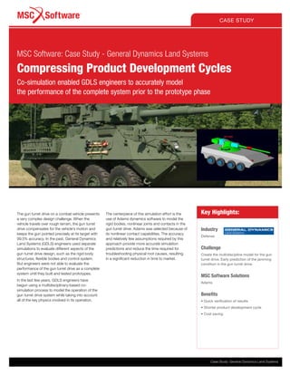
MSC Software: Case Study - General Dynamics Land Systems
Compressing Product Development Cycles
Co-simulation enabled GDLS engineers to accurately model
the performance of the complete system prior to the prototype phase
Case Study: General Dynamics Land Systems
2. Need to Consider Multi-Physics
in Design Process
GDLS builds a variety of combat vehicles such
as the Abrams M1 tank, Stryker mobile gun
system and MRAP blast- and ballistic-protected
personnel carriers. Designing these products
for optimal performance requires consideration
of a wide range of physics including rigid
body structures, flexible bodies, suspension
systems, nonlinear body to body contact,
nonlinear large scale deformation, thermal,
electrical, electromagnetic, fluid, and others.
GDLS has developed the capability to model
each of these physics individually and single-
physics simulations are performed frequently
during the design process. But each of these
simulations is heavily dependent on other
physical processes outside its scope which
makes it necessary to make assumptions
that have a negative impact on accuracy.
Traditionally, designers working on actuators,
controllers and associated electronic circuitry
have to wait for mechanical hardware to
be procured and tested before tuning their
systems to meet mechanical requirements.
This process is normally the controlling factor
for the delivery leadtime of a new product.
Overview of Co-Simulation Process
The new co-simulation process cooperatively
solves the dynamic and nonlinear contact
behavior of the mechanical system interacting
with the discrete behavior of the digital motor/
controller system. The co-simulation process
is initiated and controlled from the MATLAB/
Simulink environment using the “Adams
plant model” (which accounts for all rigid
body dynamics and flex body dynamics).
Co-simulation allows the control system model
to process discrete models using the ode4
Runge-Kutta integrator based on the variables
received from Adams. At the completion of
each time step, Simulink sends its output
to Adams and waits for the Adams solver to
calculate the solutions to its set of variables
using the GSTIFF integrator. Upon solving the
state variables, Adams sends its data over
the PIPE communications line to Simulink and
the process advances to the next time step.
Control models were simulated in Simulink.
The control system was designed for two
modes of operation. Inertial stabilized
mode stabilizes the weapon in space with
respect to perturbations in pitch and yaw.
Non-stabilized mode controls the gun in
elevation and azimuth in the local reference
frame of the vehicle. Control algorithms
were designed to include compensation for
both the rigid body dynamics along with the
bending modes of the gun/cradle system.
Modeling of Mechanical Systems
The gun turret drive CAD model was imported
into Adams including all of the assembly
tolerances required for the final product release.
In complicated machinery it’s very common
“With Adams, the early identification and understanding of the jamming
condition in the gun turret drive saved a considerable amount of time
and money in troubleshooting.”
Zhian Kuang, General Dynamics Land Systems. Sterling Heights, Michigan
Figure 1: Overview of co-simulation process
CASE STUDY
2 | MSC Software
MSC Software: Case Study - General Dynamics Land Systems
3. for cumulative tolerances to cause problems
that aren’t identified until prototype testing.
The Adams model overcomes this problem by
incorporating the tolerances of the individual
components and providing 3D redundant
constraints that incorporate the impact of the
cumulative tolerances. This makes it possible
for engineers to determine the impact of
tolerances on product behavior and investigate
the impact of tightening or loosening
tolerances prior to the prototype phase.
In this highly complex weapons system,
the ability to account for nonlinearities is
critical to accurate simulation. The key
advantage of Adams is that it accounts for
the nonlinearities in this system through its
ability to model nonlinear on/off contacts,
large displacements associated with part
deformations and nonlinear materials.
Mechanism analyses are done in Adams
to determine which bodies can remain as
computationally economical rigid bodies and
which need to be converted to computationally
more intensive flexible bodies. For example, if
the first mode frequency of a component is well
above the frequencies likely to be experienced
in operation then it is normally modeled as a
rigid body. The first mode for the assembly
consisting of the gun, breech block and
adapter is within the range of interest in free-
free modal analysis and also when constrained
by assembly conditions so it was modeled
as a flexible body. On the other hand, the first
mode of the cradle is outside the bandwidth of
interest when constrained
for assembly conditions so it was modeled as
a rigid body.
DC gear motors were used as actuators to
control the elevation of the gun. Each motor
was mechanically modeled in Adams including
the motor brake, rotor, stator and a geared
output shaft. GDLS electronic circuitry for
motor controllers was modeled in Simulink.
Torque commands from the Simulink control
system model are assigned to the output shaft.
The output shaft gear engages a sector gear
that drives the gun assembly in the reference
frame of the turret with the motion profile
incorporating the assembly tolerances.
Comparison to Measured Data
The frequency response of the Adams
plant was compared to measured data.
The simulation was run in assembly mode
incorporating the full range of potential design
positions of all parts based on their toler-
ances. The percentage difference between
the simulation predictions and physical
measurements for the frequencies of the first
five modes were respectively 3%, 18%, 10%,
10% and 17%. Allowing the system to settle
with gravitational loading closed up some
tolerances and reduced the difference for
the four and fifth modal frequencies to 0.1%
and 0.25%. It’s important to note that these
simulation predictions were generated on the
first cut analysis without tweaking the model to
match the measured data. Adjusting the details
of the joints at the attachment points affected
the frequency of modes 1 and 2, allowing
engineers to understand how joints and con-
tact forces influence the frequency response
of the mechanical system. GDLS engineers
compared the performance of simple bush-
ings, 3D contacts, classic joints and forces to
understand what each component contributed
to the responses measured in the prototype.
Detecting and Troubleshooting
Jamming
One of the most critical considerations in the
gun turret drive is the potential for jamming,
a condition in which side loading on rotating
components causes the shaft to flex and
increases the frictional force between the
shaft and bearing. In some cases, the
frictional force can rise to a level that stops
the shaft from rotating. Components subject
to jamming are normally modeled as flexible
bodies to increase simulation accuracy.
One of the key benefits of Adams is its ability
to identify jamming prior to the prototype
phase through the use of nonlinear contacts
in which friction varies depending on the
loads on the shaft and bearings and other
factors. In this application, Adams identified a
jamming condition even though the designer
was certain that the shaft would not jam. Later
when the prototype was built it was determined
that jamming did occur in the original design.
The early identification and understanding of
the problem saved a considerable amount
of time and money in troubleshooting.
A key advantage of Adams is that relatively few
assumptions are required for the plant model.
The accuracy and relatively few assumptions
required for the multiphysics approach enables
GDLS engineers to understand, negotiate
and trade off both upstream and downstream
requirements with much greater visibility to
their impact on system requirements than was
possible in the past. Knowing the impact of
subsystem performance based on physics
enables the system integrator to play a more
active role in requirements and cost control
tradeoffs as opposed to be solely driven by
suppliers’ perspectives as often occurred in
the past.
In summary, multiphysics co-simulation
requires fewer assumptions and is easier to
use for troubleshooting physical root causes
than other computer aided engineering
methods. Co-simulation of the gun turret drive
enabled GDLS engineers to accurately model
the performance of the complete system prior
to the prototype phase. The ability to identify
problems and evaluate potential solutions
and to understand the effect of component
specifications on system performance helped
significantly compress the product develop-
ment cycle. This is why GDLS engineers called
the model a ‘Virtual Machine’ built by using Ad-
ams. And the virtual machine is producing cost
savings, especially in product R&D processes.
Figure 2: First mode for gun assembly is
within range of interest so it was modeled
as flexible body
Figure 3: First modal frequency for cradle is outside
bandwidth of interest so it was modeled as rigid body
Figure 4: Adams model of DC
gear motors
CASE STUDY
Case Study: General Dynamics Land Systems 3
MSC Software: Case Study - General Dynamics Land Systems