Download to read offline

![WILDEN PUMP ENGINEERING, LLC 2 WIL-10470-E-01
NOTE: Most elastomeric materials use colored dots for identification.
NOTE: Not all models are available with all material options.
NOTE: The Wilden UL 79-listed products covered by this manual are PS1 models with the following designation: AA, followed by AA, followed by A,
followed by BNS, followed by BN, followed by A or S, followed by BN, followed by 0495. Wilden UL-Listed pumps have been evaluated for use at a 25°C
(77°F) ambient temperature with a maximum inlet pressure of 3.4 bar (50 psig).
Viton®
is a registered trademark of DuPont Dow Elastomers.
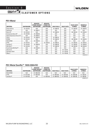
S e c t i o n 2
W I L D E N P U M P D E S I G N AT I O N S Y S T E M
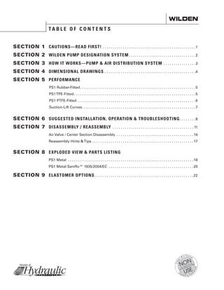
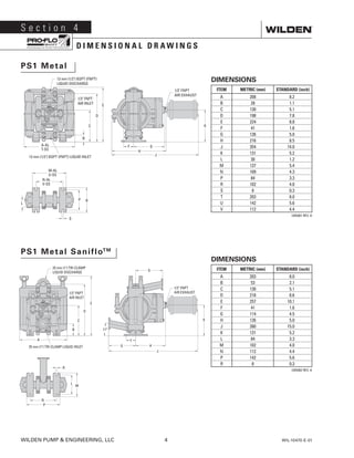
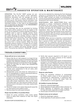
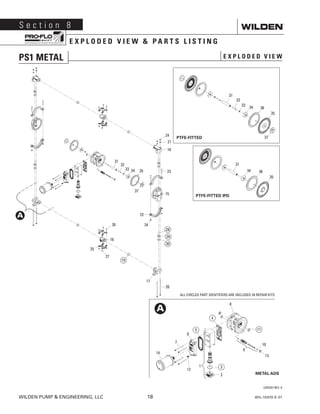
PS1 METAL
13 mm (1/2) Pump
Maximum Flow Rate:
60.2 lpm (15.9 gpm)
LEGEND XPS1 / XXXXX / XXX / XX / XXX / XXXX
O-RINGS
MODEL VALVE SEATS
VALVE BALLS
DIAPHRAGMS
AIR VALVE
CENTER BLOCK
CENTER BLOCK
WETTED PARTS OUTER PISTON
SPECIALTY
CODE
(if applicable)
MATERIAL CODES
MODEL
XPS1 = PRO-FLO®
SHIFT
XPS1 = PRO-FLO®
SHIFT ATEX
WETTED PARTS/OUTER PISTON
AA = ALUMINUM / ALUMINUM
AZ = ALUMINUM / NO OUTER
PISTON
HH = ALLOY C / ALLOY C
HZ = ALLOY C / NO OUTER PISTON
SS = STAINLESS STEEL /
STAINLESS STEEL
SZ = STAINLESS STEEL / NO
OUTER PISTON
CENTER BLOCK
AA = ALUMINUM
AIR VALVE
A = ALUMINUM
DIAPHRAGMS
BNS = BUNA-N (Red Dot)
EPS = EPDM (Blue Dot)
FBS = SANITARY BUNA 1,3
(Two Yellow Dots)
FSS = SANIFLEX™ [Hytrel®
(Cream)] 1,3
PUS = POLYURETHANE (Clear)
TEU = PTFE w/EPDM BACKUP
(White) 1,2,3
THU = PTFE W/HIGH-TEMP BUNA-N
BACK-UP (White)
TNL = PTFE W/NEOPRENE BACKUP
O-RING, IPD (White)
TNU = PTFE W/NEOPRENE BACKUP
(White)
TSU = PTFE W/SANIFLEX™ BACKUP
(White) 1,2,3
TVU = PTFE W/VITON®
BACKUP VTS
VITON®
(White Dot)
WFS = WIL-FLEX™ [Santoprene®
(Three Black Dots)]
XBS = CONDUCTIVE BUNA-N (Two
Red Dots)
VALVE BALLS
BN = BUNA-N (Red Dot)
EP = EPDM (Blue Dot)
FS = SANIFLEX™ [Hytrel®
(Cream)] 1,3
PU = POLYURETHANE (Brown)
TF = PTFE (White) 1,2,3
VT = VITON®
(Silver or White Dot)
WF = WIL-FLEX™ [Santoprene®
(Three Black Dots)]
VALVE SEATS
A = ALUMINUM
H = ALLOY C
S = STAINLESS STEEL
VALVE SEAT O-RINGS
BN = BUNA-N
EP = EPDM
FS = SANIFLEX™ [Hytrel®
(Cream)] 1,3
PU = POLYURETHANE (Brown)
TF = PTFE (White) 1,2,3
WF = WIL-FLEX™ (Santoprene®
)
SPECIALTY CODES
0014 BSPT threading
0023 Wing nuts
0067 Saniflo™ FDA, Wil-Gard 220V
0070 Saniflo™ FDA
0079 Tri-clamp fittings, wing nuts
0080 Tri-clamp fittings ONLY
0100 Wil-Gard 110V
0102 Wil-Gard sensor wires ONLY
0103 Wil-Gard 220V
0319 Single-point exhaust, BSPT
0320 Single-point exhaust
0495 UL-approved
0502 PFA-coated hardware
0603 PFA-coated hardware, Wil-Gard 110V
0067E Saniflo™ FDA, Wil-Gard 220V 1935/2004/EC
0070E Saniflo™ FDA 1935/2004/EC
0120E Saniflo™ FDA, Wil-Gard 110V 1935/2004/EC
NOTES:
1
Meets Requirements of FDA CFR21.177
2
Meets Requirements of USP Class VI
3
Meets Requirements of 1935/2004/EC](https://image.slidesharecdn.com/ps1-metal-eom-170907221555/85/Ps1-metal-eom-4-320.jpg)
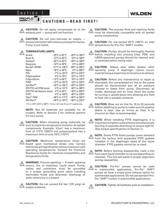
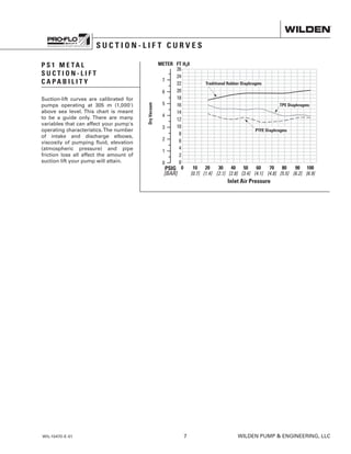
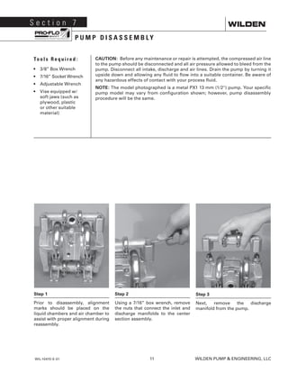
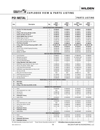
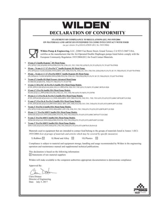
![PS1 METAL
TPE-FITTED
Flow rates indicated on chart were determined by pumping water.
For optimum life and performance, pumps should be specified so that daily operation
parameters will fall in the center of the pump's performance curve.
Flow rates indicated on chart were determined by pumping water.
For optimum life and performance, pumps should be specified so that daily operation
parameters will fall in the center of the pump's performance curve.
PS1 METAL
RUBBER-FITTED
Ship Weight............. Aluminum 6 kg (13 lb)
316 Stainless Steel 9 kg (20 lb)
Alloy C 9.5 kg (21 lb)
Air Inlet......................................6 mm (1/4”)
Inlet..........................................13 mm (1/2”)
Outlet.......................................13 mm (1/2”)
Suction Lift........................ 5.9 m Dry (19.3’)
9.8 m Wet (32.3’)
Disp. per Stroke1
.............. 0.10 L (0.027 gal)
Max. Flow Rate........... 60.2 lpm (15.9 gpm)
Max. Size Solids................... 1.6 mm (1/16”)
1
Displacement per stroke was calculated at
4.8 bar (70 psig) air inlet pressure against a
2.1 bar (30 psig) head pressure.
Example: To pump 20.1 lpm (5.3 gpm)
against a discharge head of 3.4 bar (50
psig) requires 4.1 bar (60 psig) and 7.7
Nm3
/h (4.8 scfm) air consumption.
Caution: Do not exceed 8.6 bar (125 psig)
air supply pressure.
Ship Weight............. Aluminum 6 kg (13 lb)
316 Stainless Steel 9 kg (20 lb)
Alloy C 9.5 kg (21 lb)
Air Inlet......................................6 mm (1/4”)
Inlet..........................................13 mm (1/2”)
Outlet.......................................13 mm (1/2”)
Suction Lift........................ 5.7 m Dry (18.7’)
8.3 m Wet (27.2’)
Disp. per Stroke1
.............. 0.10 L (0.026 gal)
Max. Flow Rate........... 60.2 lpm (15.9 gpm)
Max. Size Solids....................1.6 mm (1/16)
1
Displacement per stroke was calculated at
4.8 bar (70 psig) air inlet pressure against a
2.1 bar (30 psig) head pressure.
Example: To pump 20.8 lpm (5.5 gpm)
against a discharge head of 3.4 bar (50
psig) requires 4.1 bar (60 psig) and 8.3
Nm3
/h (5.2 scfm) air consumption.
Caution: Do not exceed 8.6 bar (125 psig)
air supply pressure.
12[20]
16[27]
2 4 6 8 10 12 14 16
[8] [15] [23] [30] [38] [45] [53] [61]
8[14]
4[7]
WIL-10470-E-01 5 WILDEN PUMP ENGINEERING, LLC
S e c t i o n 5
P E R F O R M A N C E
12[20]
16[27]
2 4 6 8 10 12 14 16
[8] [15] [23] [30] [38] [45] [53] [61]
8[14]
4[7]](https://image.slidesharecdn.com/ps1-metal-eom-170907221555/85/Ps1-metal-eom-7-320.jpg)
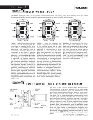
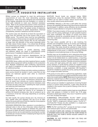
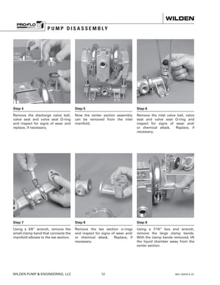
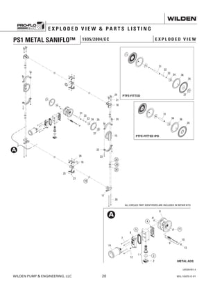
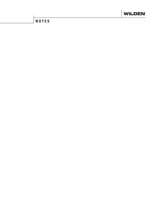
![Flow rates indicated on chart were determined by pumping water.
For optimum life and performance, pumps should be specified so that daily operation
parameters will fall in the center of the pump's performance curve.
PS1 METAL
PTFE-FITTED
12[20]
16[27]
2 4 6 8 10 12 14 16
[8] [15] [23] [30] [38] [45] [53] [61]
8[14]
4[7]
Ship Weight............. Aluminum 6 kg (13 lb)
316 Stainless Steel 9 kg (20 lb)
Alloy C 9.5 kg (21 lb)
Air Inlet......................................6 mm (1/4”)
Inlet..........................................13 mm (1/2”)
Outlet.......................................13 mm (1/2”)
Suction Lift........................ 4.3 m Dry (14.2’)
9.7 m Wet (31.7’)
Disp. per Stroke1
.............. 0.10 L (0.026 gal)
Max. Flow Rate........... 59.8 lpm (15.8 gpm)
Max. Size Solids................... 1.6 mm (1/16”)
1
Displacement per stroke was calculated at
4.8 bar (70 psig) air inlet pressure against a
2.1 bar (30 psig) head pressure.
Example: To pump 17.4 lpm (4.6 gpm)
against a discharge head of 2.1 bar (30
psig) requires 2.8 bar (40 psig) and 5.9
Nm3
/h (3.5 scfm) air consumption.
Caution: Do not exceed 8.6 bar (125 psig)
air supply pressure.
WILDEN PUMP ENGINEERING, LLC 6 WIL-10470-E-01
P E R F O R M A N C E](https://image.slidesharecdn.com/ps1-metal-eom-170907221555/85/Ps1-metal-eom-8-320.jpg)

This document provides operation and maintenance instructions for a Wilden PS1 metal diaphragm pump. It includes sections on cautions, pump designations, how the pump works, dimensions, performance specifications, installation/operation tips, disassembly/reassembly instructions, exploded diagrams, and material options. The document instructs users on safety guidelines, operating limits, maintenance procedures, and replacement part identification for the Wilden PS1 pump.


