This document provides instructions for removing and installing the engine on Case CX330 and CX350 crawler excavators. It outlines 17 steps for removing the engine, including disconnecting electrical connections, fuel lines, hydraulic pump, radiator/oil cooler assembly, and lifting the engine from the machine. When installing the engine, the steps are reversed. Safety precautions are provided, and it is noted that flexible engine mounts and retaining hardware should be inspected and replaced if needed.
"Trans Failsafe Prog" on your BMW X5 indicates potential transmission issues requiring immediate action. This safety feature activates in response to abnormalities like low fluid levels, leaks, faulty sensors, electrical or mechanical failures, and overheating.
Fleet management these days is next to impossible without connected vehicle solutions. Why? Well, fleet trackers and accompanying connected vehicle management solutions tend to offer quite a few hard-to-ignore benefits to fleet managers and businesses alike. Let’s check them out!
Ever been troubled by the blinking sign and didn’t know what to do?
Here’s a handy guide to dashboard symbols so that you’ll never be confused again!
Save them for later and save the trouble!
Why Is Your BMW X3 Hood Not Responding To Release CommandsDart Auto
Experiencing difficulty opening your BMW X3's hood? This guide explores potential issues like mechanical obstruction, hood release mechanism failure, electrical problems, and emergency release malfunctions. Troubleshooting tips include basic checks, clearing obstructions, applying pressure, and using the emergency release.
Things to remember while upgrading the brakes of your carjennifermiller8137
Upgrading the brakes of your car? Keep these things in mind before doing so. Additionally, start using an OBD 2 GPS tracker so that you never miss a vehicle maintenance appointment. On top of this, a car GPS tracker will also let you master good driving habits that will let you increase the operational life of your car’s brakes.
Comprehensive program for Agricultural Finance, the Automotive Sector, and Empowerment . We will define the full scope and provide a detailed two-week plan for identifying strategic partners in each area within Limpopo, including target areas.:
1. Agricultural : Supporting Primary and Secondary Agriculture
• Scope: Provide support solutions to enhance agricultural productivity and sustainability.
• Target Areas: Polokwane, Tzaneen, Thohoyandou, Makhado, and Giyani.
2. Automotive Sector: Partnerships with Mechanics and Panel Beater Shops
• Scope: Develop collaborations with automotive service providers to improve service quality and business operations.
• Target Areas: Polokwane, Lephalale, Mokopane, Phalaborwa, and Bela-Bela.
3. Empowerment : Focusing on Women Empowerment
• Scope: Provide business support support and training to women-owned businesses, promoting economic inclusion.
• Target Areas: Polokwane, Thohoyandou, Musina, Burgersfort, and Louis Trichardt.
We will also prioritize Industrial Economic Zone areas and their priorities.
Sign up on https://profilesmes.online/welcome/
To be eligible:
1. You must have a registered business and operate in Limpopo
2. Generate revenue
3. Sectors : Agriculture ( primary and secondary) and Automative
Women and Youth are encouraged to apply even if you don't fall in those sectors.
Core technology of Hyundai Motor Group's EV platform 'E-GMP'Hyundai Motor Group
What’s the force behind Hyundai Motor Group's EV performance and quality?
Maximized driving performance and quick charging time through high-density battery pack and fast charging technology and applicable to various vehicle types!
Discover more about Hyundai Motor Group’s EV platform ‘E-GMP’!
5 Warning Signs Your BMW's Intelligent Battery Sensor Needs AttentionBertini's German Motors
IBS monitors and manages your BMW’s battery performance. If it malfunctions, you will have to deal with an array of electrical issues in your vehicle. Recognize warning signs like dimming headlights, frequent battery replacements, and electrical malfunctions to address potential IBS issues promptly.
What Exactly Is The Common Rail Direct Injection System & How Does It WorkMotor Cars International
Learn about Common Rail Direct Injection (CRDi) - the revolutionary technology that has made diesel engines more efficient. Explore its workings, advantages like enhanced fuel efficiency and increased power output, along with drawbacks such as complexity and higher initial cost. Compare CRDi with traditional diesel engines and discover why it's the preferred choice for modern engines.
What Does the PARKTRONIC Inoperative, See Owner's Manual Message Mean for You...Autohaus Service and Sales
Learn what "PARKTRONIC Inoperative, See Owner's Manual" means for your Mercedes-Benz. This message indicates a malfunction in the parking assistance system, potentially due to sensor issues or electrical faults. Prompt attention is crucial to ensure safety and functionality. Follow steps outlined for diagnosis and repair in the owner's manual.
In this presentation, we have discussed a very important feature of BMW X5 cars… the Comfort Access. Things that can significantly limit its functionality. And things that you can try to restore the functionality of such a convenient feature of your vehicle.
𝘼𝙣𝙩𝙞𝙦𝙪𝙚 𝙋𝙡𝙖𝙨𝙩𝙞𝙘 𝙏𝙧𝙖𝙙𝙚𝙧𝙨 𝙞𝙨 𝙫𝙚𝙧𝙮 𝙛𝙖𝙢𝙤𝙪𝙨 𝙛𝙤𝙧 𝙢𝙖𝙣𝙪𝙛𝙖𝙘𝙩𝙪𝙧𝙞𝙣𝙜 𝙩𝙝𝙚𝙞𝙧 𝙥𝙧𝙤𝙙𝙪𝙘𝙩𝙨. 𝙒𝙚 𝙝𝙖𝙫𝙚 𝙖𝙡𝙡 𝙩𝙝𝙚 𝙥𝙡𝙖𝙨𝙩𝙞𝙘 𝙜𝙧𝙖𝙣𝙪𝙡𝙚𝙨 𝙪𝙨𝙚𝙙 𝙞𝙣 𝙖𝙪𝙩𝙤𝙢𝙤𝙩𝙞𝙫𝙚 𝙖𝙣𝙙 𝙖𝙪𝙩𝙤 𝙥𝙖𝙧𝙩𝙨 𝙖𝙣𝙙 𝙖𝙡𝙡 𝙩𝙝𝙚 𝙛𝙖𝙢𝙤𝙪𝙨 𝙘𝙤𝙢𝙥𝙖𝙣𝙞𝙚𝙨 𝙗𝙪𝙮 𝙩𝙝𝙚 𝙜𝙧𝙖𝙣𝙪𝙡𝙚𝙨 𝙛𝙧𝙤𝙢 𝙪𝙨.
Over the 10 years, we have gained a strong foothold in the market due to our range's high quality, competitive prices, and time-lined delivery schedules.
Case cx350 crawler excavator service repair manual
1. Copyright 2002 Case France
Printed in France
Case Cre 9-43570GB March 2002
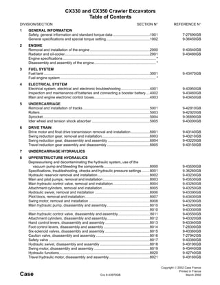
CX330 and CX350 Crawler Excavators
Table of Contents
DIVISION/SECTION SECTION N° REFERENCE N°
1 GENERAL INFORMATION
Safety, general information and standard torque data .....................................1001 7-27690GB
General specifications and special torque setting............................................1002 9-36450GB
2 ENGINE
Removal and installation of the engine ............................................................2000 9-43540GB
Radiator and oil-cooler.....................................................................................2001 9-43480GB
Engine specifications ............................................................................................. *
Disassembly and assembly of the engine.............................................................. *
3 FUEL SYSTEM
Fuel tank ..........................................................................................................3001 9-43470GB
Fuel engine system................................................................................................ *
4 ELECTRICAL SYSTEM
Electrical system, electrical and electronic troubleshooting.............................4001 9-40950GB
Inspection and maintenance of batteries and connecting a booster battery....4002 9-43460GB
Main and engine electronic control boxes........................................................4003 9-43450GB
5 UNDERCARRIAGE
Removal and installation of tracks ...................................................................5001 9-42910GB
Rollers..............................................................................................................5003 9-42920GB
Sprocket...........................................................................................................5004 9-36890GB
Idler wheel and tension shock absorber ..........................................................5005 9-43000GB
6 DRIVE TRAIN
Drive motor and final drive transmission removal and installation ...................6001 9-43140GB
Swing reduction gear, removal and installation................................................6003 9-43210GB
Swing reduction gear, disassembly and assembly ..........................................6004 9-43220GB
Travel reduction gear assembly and disassembly ...........................................6005 9-43150GB
7 UNDERCARRIAGE HYDRAULICS
8 UPPERSTRUCTURE HYDRAULICS
Depressurising and decontaminating the hydraulic system, use of the
vacuum pump and bleeding the components..............................................8000 9-43500GB
Specifications, troubleshooting, checks and hydraulic pressure settings ........8001 9-36260GB
Hydraulic reservoir removal and installation ....................................................8002 9-43230GB
Main and pilot pumps, removal and installation ...............................................8003 9-43530GB
Main hydraulic control valve, removal and installation.....................................8004 9-43260GB
Attachment cylinders, removal and installation................................................8005 9-43250GB
Hydraulic swivel, removal and installation .......................................................8006 9-43390GB
Pilot blocs, removal and installation.................................................................8007 9-43400GB
Swing motor, removal and installation .............................................................8008 9-43200GB
Main hydraulic pump, disassembly and assembly...........................................8010 9-43240GB
.........................................................................................................................8010 9-43330GB
Main hydraulic control valve, disassembly and assembly................................8011 9-43550GB
Attachment cylinders, disassembly and assembly...........................................8012 9-43320GB
Hand control levers, disassembly and assembly .............................................8013 9-43340GB
Foot control levers, disassembly and assembly ..............................................8014 7-28300GB
Six-solenoid valves, disassembly and assembly .............................................8015 9-43360GB
Caution valve, disassembly and assembly ......................................................8016 7-27942GB
Safety valve .....................................................................................................8017 9-43380GB
Hydraulic swivel, disassembly and assembly ..................................................8018 9-43190GB
Swing motor, disassembly and assembly ........................................................8019 9-43440GB
Hydraulic functions...........................................................................................8020 9-42740GB
Travel hydraulic motor, disassembly and assembly.........................................8021 9-43160GB
2. Cre 9-43570GB Edition 03-02
DIVISION/SECTION SECTION N° REFERENCE N°
9 UPPERSTRUCTURE
Upperstructure, turntable and counterweight...................................................9002 9-43410GB
Boom, dipper and bucket.................................................................................9003 9-43420GB
Seat and seat belt............................................................................................9004 9-40460GB
Cab and cab equipment...................................................................................9005 9-43430GB
Air conditioning troubleshooting.......................................................................9006 7-xxxxxFR
Air conditioning unit disassembly and assembly..............................................9007 7-29910GB
Air conditioning servicing .................................................................................9008 7-xxxxxFR
Air conditioning components............................................................................9009 7-xxxxxFR
Large format hydraulic and electrical schematics .........................................Pocket 9-35930GB
* Consult the Engine Service Manual
Sections to be distributed at a later date
NOTE: CASE Company reserves the right to make changes in the spec-
ification and design of the machine without prior notice and without
incurring any obligation to modify units previously sold.
The description of the models shown in this manual has been made in
accordance with the technical specifications known as of the date of
design of this document.
3. Case
Copyright 2000 Case France
Printed in France
September 2000Cre 7-27690GB
1001
SAFETY, GENERAL INFORMATION
AND STANDARD TORQUE DATA
Section
1001
4. 1001-3
Cre 7-27690GB Issued 09-00
GENERAL INFORMATION
Cleaning
Clean all metal parts except bearings, in a suitable
cleaning solvent or by steam cleaning. Do not use
caustic soda for steam cleaning. After cleaning, dry
and put oil on all parts. Clean oil passages with
compressed air. Clean bearings in a suitable cleaning
solvent. Dry the bearings completely and put oil on
the bearings.
Inspection
Check all parts when the parts are disassembled.
Replace all parts that have wear or damage. Small
scoring or grooves can be removed with a hone or
crocus cloth. Complete a visual inspection for
indications of wear, pitting and the replacement of
parts necessary to prevent early failures.
Bearings
Check bearings for easy action. If bearings have a
loose fit or rough action, replace the bearing. Wash
bearings with a suitable cleaning solvent and permit
to air dry. DO NOT DRY BEARINGS WITH
COMPRESSED AIR.
Needle Bearings
Before you press needle bearings in a bore always
remove any metal protrusions in the bore or edge of
the bore. Before you press bearings into position, put
petroleum jelly on the inside and outside diameter of
the bearings.
Gears
Check all gears for wear and damage. Replace gears
that have wear or damage.
Oil Seals, O-rings and Gaskets
Always install new oil seals, O-rings and gaskets. Put
petroleum jelly on seals and O-rings.
Shafts
Check all shafts that have wear or damage. Check
the bearing and oil seal surfaces of the shafts for
damage.
Service Parts
Always install genuine Case service parts. When
ordering refer to the Parts Catalog for the correct part
number of the genuine Case replacement items.
Failures due to the use of other than genuine Case
replacement parts are not covered by warranty.
Lubrication
Only use the oils and lubricants specified in the
Operator’s or Service Manuals. Failures due to the
use of non-specified oils and lubricants are not
covered by warranty.
5. 1001-4
Cre 7-27690GB Issued 09-00
SAFETY
This symbol means ATTENTION! BECOME ALERT! YOUR
SAFETY IS INVOLVED. The message that follows the
symbol contains important information about safety. Carefully
read the message. Make sure you fully understand the
causes of possible injury or death.
!
To prevent injury always follow the Warning, Caution
and Danger notes in this section and throughout the
manual.
Place a “Do not operate“ tag on the starter switch key
before carrying out any service or repair work on the
machine.
.
WARNING: Read the operator’s manual to
familiarize yourself with the correct control
functions.
!
WARNING: Operate the machine and
equipment controls from the seat position
only. Any other method could result in
serious injury.
!
WARNING: This is a one man machine, no
riders allowed.!
WARNING: Before starting engine, study
Operator’s Manual safety messages. Read
all safety signs on machine. Clear the area of
other persons. Learn and practice safe use
of controls before operating.
It is your responsibility to understand and
follow manufacturers instructions on
machine operation, service and to observe
pertinent laws and regulations. Operator’s
and Service Manuals may be obtained from
your Case dealer.
!
WARNING: If you wear clothing that is too
loose or do not use the correct safety
equipment for your job, you can be injured.
Always wear clothing that will not catch on
objects. Extra safety equipment that can be
required includes hard hat, safety shoes, ear
protection, eye or face protection, heavy
gloves and reflector clothing.
!
WARNING: When working in the area of the
fan belt with the engine running, avoid loose
clothing if possible, and use extreme caution.
!
WARNING: When doing checks and tests
on the equipment hydraulics, follow the
procedures as they are written. DO NOT
change the procedure.
!
WARNING: When putting the hydraulic
cylinders on this machine through the
necessary cycles to check operation or to
remove air from a circuit, make sure all
people are out of the way.
!
6. 1001-5
Cre 7-27690GB Issued 09-00
WARNING: Use insulated gloves or mittens
when working with hot parts.!
WARNING: Lower all attachments to the
ground or use stands to safely support the
attachments before you do any maintenance
or service.
!
WARNING: Pin sized and smaller streams
of hydraulic oil under pressure can penetrate
the skin and result in serious infection. If
hydraulic oil under pressure does penetrate
the skin, seek medical treatment
immediately. Maintain all hoses and tubes in
good condition. Make sure all connections
are tight. Make a replacement of any tube or
hose that is damaged or thought to be
damaged. DO NOT use your hand to check
for leaks, use a piece of cardboard or wood.
!
WARNING: When removing hardened pins
such as a pivot pin, or a hardened shaft, use
a soft head (brass or bronze) hammer or use
a driver made from brass or bronze and a
steel head hammer.
!
WARNING: When using a hammer to
remove and install pivot pins or separate
parts using compressed air or using a
grinder, wear eye protection that completely
encloses the eyes (approved goggles or
other approved eye protectors).
!
WARNING: Use suitable floor (service)
jacks or chain hoist to raise wheels or tracks
off the floor. Always block machine in place
with suitable safety stands.
!
WARNING: When servicing or repairing the
machine, keep the shop floor and operator’s
compartment and steps free of oil, water,
grease, tools, etc. Use an oil absorbing
material and/or shop cloths as required. Use
safe practices at all times.
!
WARNING: Some components of this
machine are very heavy. Use suitable lifting
equipment or additional help as instructed in
this Service Manual.
!
WARNING: Engine exhaust fumes can
cause death. If it is necessary to start the
engine in a closed place, remove the exhaust
fumes from the area with an exhaust pipe
extension. Open the doors and get outside
air into the area.
!
WARNING: When the battery electrolyte is
frozen, the battery can explode if (1), you try
to charge the battery, or (2), you try to jump
start and run the engine. To prevent the
battery electrolyte from freezing, try to keep
the battery at full charge. If you do not follow
these instructions, you or others in the area
can be injured.
!
7. Case
Copyright Ó 2002 Case France
Printed in France
March 2002Cre 9-43540GB
2000
REMOVAL AND INSTALLATION
OF THE ENGINE
Section
2000
8. 2000-3
Cre 9-43540GB Issued 03-02
ENGINE
Removal and installation
STEP 1
JS00163A
Park the machine on hard, flat ground. Lower the
attachment to the ground.
STEP 2
Release pressure in the hydraulic system and in the
hydraulic reservoir (see Section 8000).
STEP 3
CD01C162
Disconnect the battery ground (-) cable (1) from the
battery.
STEP 4
Refer to Section 8003 and remove the hydraulic
pump.
STEP 5
Refer to Section 2001 and remove the radiator and
oil-cooler assembly.
STEP 6
CD02C151
Remove the engine shutdown control (arrow).
Disconnect the fuel supply pipe (1) and the fuel return
pipe (2) and plug them.
STEP 7
CD01D131
Remove the screws (1) from the compressor and put
it away from the engine.
1
1
2
1
1
9. 2000-4
Cre 9-43540GB Issued 03-02
STEP 8
CD02C152
Label and disconnect the electrical connections from
the water temperature sensor (1).
STEP 9
CD02C153
Label and disconnect the electrical connections from
the oil pressure sensor (1).
STEP 10
CD00J030
Label and disconnect the electrical supply (1) to the
pre-heating plugs.
STEP 11
CD02C154
Label and disconnect the electrical connections to
the starter motor (1). Remove the earth cable (2) at
the engine end.
STEP 12
CD02C152
Label and disconnect the electrical connections of
the electronic regulation (1) from the engine.
STEP 13
CD02C155
Remove the hose connecting the turbo-charger to the
air filter (1).
1
1
1
1
2
1
1
10. 2000-5
Cre 9-43540GB Issued 03-02
STEP 14
CD01M004
Label and disconnect the electrical connections to
the alternator (arrows).
STEP 15
Remove all the clips, etc, which fasten the electrical
harnesses to the engine and move the harnesses out
of the way.
STEP 16
Install a suitable lifting device on the engine lifting
rings (for the weight of the engine, see Section 1002).
STEP 17
Remove the engine retaining hardware.
NOTE: When installing, make a visual inspection of
the condition of the rubber flexible mountings and
change them if necessary. Respect the colours, light
blue on the fan side, light green on the hand-wheel
side. Tighten the engine retaining screws to a torque of
313 ± 25 Nm.
STEP 18
When there is nothing interfering with the removal of
the engine, raise the engine carefully and install it on
a suitable repair bench.
NOTE: When installing the engine in the machine,
proceed in the reverse order from removal.
Before operating the machine, carry out the following
operations:
- Bleed and prime the fuel system (see Operator’s
Manual).
- Fill and bleed the engine cooling system (see Oper-
ator’s Manual).
- Check the hydraulic, fuel and cooling systems for
leaks.
- Check the oil level in the hydraulic reservoir. Top up
if necessary.
11. Thank you very much for
your reading. Please Click
Here. Then Get COMPLETE
MANUAL. NO WAITING
NOTE:
If there is no response to
click on the link above,
please download the PDF
document first and then
click on it.
13. 2001-4
Cre 9-43480GB Issued 03-02
RADIATOR AND OIL-COOLER
Before carrying out any operation on the machine, perform the following operations in the order shown:
- Park the machine on hard, flat ground.
- Lower the attachment to the ground.
- Shut down the engine.
- Remove the starter switch key.
- Make sure that pressure in the hydraulic system has been completely released (see Operator’s Manual).
Removal of the radiator and oil-
cooler assembly
STEP 1
CD01K055
Remove the hood (1) from the engine.
STEP 2
Remove the inner cover plate from the engine.
STEP 3
Remove the cap from the expansion reservoir.
IMPORTANT: Do not remove the cap when the
engine is hot, since the system would still be under
pressure and you could be scalded.
STEP 4
Drain the cooling system (see Operator’s Manual).
STEP 5
Release pressure in the hydraulic reservoir to allow
the vacuum pump to be mounted (see Section 8000).
NOTE: The numbers within brackets refer to the fig-
ure on page 3.
STEP 6
Remove the screws (1), then the pipe (2) from the oil
cooler (3), finally drain the latter into a clean con-
tainer.
STEP 7
Disconnect the radiator hoses (5) and (6) from the oil-
cooler, finally drain the latter into a clean container.
STEP 8
Remove the expansion reservoir hose (8) from the
radiator (7). Disconnect the return hose (9) and the
water pump suction hose (10) from the engine.
STEP 9
Disconnect the radiator hose (11) from the oil drain
plug.
STEP 10
CS02C554
Remove the screws (A) and remove the guardrails
(B). Remove the screws (C).
WARNING: When the machine is working, the engine components and the hydraulic pump reach a high
temperature. To avoid being burnt by hot metal or scalded by high temperature water or oil, allow the
machine to cool down before starting any servicing operation.
!
1
A
B
C
14. 2001-5
Cre 9-43480GB Issued 03-02
STEP 11
CS00G513
Pass a suitable sling right around the radiator and oil-
cooler assembly and, using a suitable lifting device,
remove the radiator and oil-cooler assembly.
NOTE: During the lifting operation, unlock the radia-
tor and oil-cooler assembly in order to free the engine
cooling fan.
Installation
When installing, proceed in the reverse order from
that of removal.
Before operating the machine:
- Check the oil level in the hydraulic reservoir. Top up
if necessary.
- Check the hydraulic fluid cooling circuit for leaks.
- Fill and bleed the engine cooling system (see Oper-
ator’s Manual).
- Check the engine cooling system for leaks.
15. 3001-3
Cre 9-43470GB Issued 03-02
FUEL TANK
Removal
STEP 1
JS00163A
Park the machine on hard, flat ground. Lower the
attachment to the ground.
STEP 2
Reduce the engine speed to idle for 30 seconds, then
shut down the engine.
STEP 3
Turn the ignition key to "ON" without starting the
engine.
STEP 4
Attach a "DO NOT OPERATE" tag to the ignition key
in the cab.
STEP 5
NOTE: The numbers within brackets refer to the fig-
ures on pages 5 and 6.
Remove the access panel under the fuel reservoir (1).
STEP 6
Open the filling plug (2) of the tank (1). Bleed the
remaining fuel using the valve (3) then remove the
latter. Remove the filter (19) and the fuel gauge (20).
STEP 7
Lift the hood of the front boot. Remove the retaining
screw (4) of the access ramp (5). Remove the access
ramp (5).
STEP 8
Remove the screws (6) on top and then inside the
front boot, then remove the protective housing (7).
STEP 9
Remove the screws (8) and the protective plate (9)
from on top of the fuel reservoir (1).
STEP 10
Loosen the two screws (10) located under the
machine. Open the side portion of the machine and
remove the two screws (11) located on the RH side of
the fuel reservoir (1). Remove the protective plate of
the reservoir (12).
STEP 11
Remove the two screws that hold the fuel oil filter.
Attach labels on the two hoses. Remove the fuel oil
filter by removing the two hoses and the retaining
clips.
STEP 12
Shift the plastic protection (13) from the fuel sensor
(14). Remove the retaining screws (15) then the fuel
sensor (14) as well as the seal (16).
STEP 13
Remove the six screws (17) from the fuel tank (1),
and the shims (18).
STEP 14
Remove the fuel tank (1) using a hoist.
STEP 15
See the operator's manual for removing the fuel filter.